This is the author’s version of a work that was submitted to / accepted for publication.
Citation for final published version:
Li, Chuanyue, Liang, Jun and Wang, Sheng-Weng 2018. Interlink hybrid DC circuit breaker. IEEE
Transactions on Industrial Electronics file
Publishers page:
Please note:
Changes made as a result of publishing processes such as copy-editing, formatting and page
numbers may not be reflected in this version. For the definitive version of this publication, please
refer to the published source. You are advised to consult the publisher’s version if you wish to cite
this paper.
This version is being made available in accordance with publisher policies. See
http://orca.cf.ac.uk/policies.html for usage policies. Copyright and moral rights for publications
made available in ORCA are retained by the copyright holders.
Abstract—To protect HVDC grids from DC faults, the
concept of a hybrid DC circuit breaker is widely accepted due to its low conduction losses and fast interruption speed. For a well-built DC grid, a massive number of hybrid DC circuit breakers have to be installed. This will lead to high capital costs. An interlink DC circuit breaker based on an idea of sharing main breaker branch between two circuit breakers is proposed to reduce the overall costs of circuit breakers in a DC grid. Comparing with existing hybrid DC circuit breakers, the interlink hybrid DC circuit breaker can achieve the same DC fault interruption capability with fewer components. Novel structures of main breaker branches are designed and their parameters are determined to make the interlink hybrid DC circuit breakers be capable for both unidirectional and bidirectional interruption on demand. For a unidirectional interlink hybrid DC circuit breaker, the size of MOVs is reduced by 50%. For a bidirectional interlink hybrid HVDC circuit breaker, the number of IGBTs and MOVs are reduced by 25%. The interlink hybrid DC breakers are verified and compared to the hybrid DC circuit breaker via a three-terminal HVDC grid in PSCAD/EMTDC.
Index Terms—HVDC grid, hybrid HVDC circuit breaker I. INTRODUCTION
he DC grid based on voltage-source-converter (VSC) technology is a preferable choice for transmitting power from remote energy sources to multiple load centers. A major challenge is the DC grid protection. Compared to an AC transmission system, the impedance within a DC grid is much lower. Therefore, the propagation of a fault in a DC grid will be much faster than that in AC systems, which further leads to the fast DC fault current rising and DC voltage drop. The DC fault current has no zero crossing. Traditional mechanical circuit breakers are not suitable for protecting a DC grid from a DC fault. Technical advance in DC circuit breakers which can interrupt a DC fault current in 5 ms is then demanded.
Semiconductor switches, such as IGBT and IGCT, can interrupt fault current within 1 ms. A string of semiconductor switches in series, as a DC circuit breaker, can easily fulfil the speed demand of the protection. However, its on-state loss is high. The loss typically is 30% of the loss of a VSC converter with same voltage rating [1]. A highly efficient cooling system is also required for this breaker to maintain its functionality.
Manuscript received August 11, 2017; revised November 08, 2017; accepted January 20, 2018. This work was supported in part by the China Scholarship Council under Grant 201408060016 and the FP7 project BEST PATHS.
Chuanyue Li, Jun Liang and Sheng Wang are with the School of Engineering, Cardiff University, Cardiff, UK. (e-mail: [email protected], [email protected], [email protected])
To reduce the on-state loss of pure-semiconductor DC circuit breaker, a hybrid DC circuit breaker (HCB) was therefore proposed to fulfil the speed and loss requirements. Its basic operation principle is that the normal load current flows through the low-loss branch in normal condition. When a DC fault is detected, the fault current is commutated to the main breaker branch to interrupt. The prototypes of HCBs were proposed by several manufacturers. ABB has tested its HCB [2] which interrupts a DC fault current up to 16 kA in 2.25 ms. An HCB prototype developed by Alstom Grid [3] interrupts a prospective fault current of 7 kA in 2.5 ms. The State Grid Smart Grid Research Institute has also developed a full-bridge-based HCB [4] which interrupts the fault current up to 15 kA within 3ms.
These HCBs have shown good performance for interrupting DC fault current. However, the costs of a future commercial HCB can be very high because a large number of semiconductor devices are used [5]. Therefore, many studies on reducing the cost of a HCB have been carried out. The low-loss branch is replaced by an SF6 switch in [6]. Its arc voltage is large enough to commutate the fault current to main breaker branch. A unidirectional HCB [7] using half number of IGBT modules is proposed with the ability to interrupt the unidirectional fault current. The DC grid protection via unidirectional HCBs is proposed in [8] to reduce the overall cost of hybrid DC circuit breakers. A H-bridge hybrid DC circuit breaker [9] can change the bidirectional fault current into the unidirectional fault current, therefore only the unidirectional main breaker branch is applied. The number of low-loss branches is increased in order to construct the H-bridge circuit. The size of the MOV in parallel connection with the main breaker can be reduced via a thyristor-based limiting circuit [10].
For a DC grid, there are terminals connected to multiple transmission lines. The conventional approach uses one HCB installed at each line end. Each HCB consists of a main breaker branch to interrupt the fault current. If the main breaker branch is shared among the HCBs, the utilization of the device is increased and the cost is reduced. Many studies based on the shared main breaker branch have been carried out. An assembly HVDC breaker [11] uses only one grounded active short-circuit breaker for each terminal to interrupt the fault occurred on any connected transmission line. Additional auxiliary switches installed on each line are required. A multi-line hybrid DC circuit breaker [12] [13] that allows all connected lines to use only one main breaker branch is proposed at the cost of requiring double low loss branches. A DC switch yard [14] and a multi-port hybrid DC circuit breaker [15] are designed to share a part of main breaker branches among connected lines.
Interlink hybrid DC circuit breaker
Chuanyue Li, Member, IEEE, Jun Liang, Senior Member, IEEE, and Sheng Wang, Member,
IEEE
Additional low-loss branches are still required.
There is the concern over the shared main breaker branch for dealing with multiple faults occurring at the same time. The sum fault current to be interrupted could be over its rating, such as the breakers proposed in [12][13][15]. However, sharing main breaker branch is still a cost-effective solution as the presence of multiple faults occurring on different transmission lines at the same time is extremely rare.
In this paper, an interlink hybrid DC circuit breaker (IHCB) based on the concept of sharing main breaker branch is proposed to reduce the size of the main breaker branches without increasing the number of low loss branches. Considering the potential demand of a unidirectional breaker that will use fewer components than a bidirectional breaker, both unidirectional and bidirectional IHCB are designed. The application of a IHCB is for the situation that 3 or more DC lines are connected to a DC bus bar, but only 2 lines are connected to the IHCB, which consists of one main breaker branch and two low loss branches. The operation between a main breaker branch and two low-loss branches are designed to ensure correct protection against faults on two transmission lines and the DC bus. The parameter of unidirectional and bidirectional IHCBs will be investigated and compared to the HCBs.
The IHCB studied in this paper is based on the HCB [2]. A detailed description of the HCB is introduced in Section II. The topology of the unidirectional and bidirectional IHCBs and their parameter analysis are proposed in Section III and VI individually. A test circuit is proposed to compare the interruption ability of the fault current and the fault current distribution of IHCB and the HCB in Section V. The conclusion is drawn in Section IV
II. HYBRID HVDC CIRCUIT BREAKER
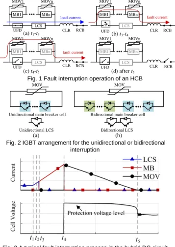
An HCB is comprised of two branches, low-loss branch and main breaker branch. The low-loss branch contains an ultrafast disconnector (UFD) and a load commutation switch (LCS), see Fig. 1. The ultrafast disconnector [16] is a mechanical switch which can open within 2 ms to isolate the load commutation switch from the main circuit. The load commutation switch, that consists of a few IGBT modules[17], is designed to provide a low-loss current path for the load current. When a fault is detected, the load commutation switch is switched off and the fault current will be commutated into the main breakers. The commutation time is normally 0.25 ms [17].
The main breaker branch is sectionalized into several main break cells [18]. Each cell contains one MOV and one main breaker (MB), see Fig. 1. Each main breaker consists of a large number of IGBT modules. In IGBT modules, diodes are anti-parallel connected with IGBTs. The main breakers stay on-state during the normal condition. The load current only flows through the low-loss branch due to the high on-state resistance of main breakers. The MOV is used to protect the main breaker from overvoltage and dissipate the fault energy.
The HCB can break either unidirectional or bidirectional fault current depending on the connection of IGBT modules applied in the load commutation switch and the main breaker.
The connection of the IGBT modules for unidirectional interruption or bidirectional interruption is shown in Fig. 2. The number of IGBT modules in a bidirectional HCB is twice of a unidirectional HCB.
A current limiting reactor (CLR) is used to limit the increasing speed of fault current no more than 3.5 kA/ms [1]. The residual current breaker (RCB) is used to disconnect the HCB physically, typically within 1 s when the residual current is small enough.
The operation of the HCB is shown in Fig. 1. When a DC fault happens at t1, the load current flowing through the low-loss branch will rise rapidly. The HCB will take some time to detect the fault (t1-t2). Then the load commutation switch is switched off immediately at t2 and hence the fault current starts to be commutated to main breakers. When the fault current is fully commutated into main breakers at t3 and the ultrafast disconnector starts to open, see Fig. 1(b). Once the ultrafast disconnector opens at t4, main breakers are switched off to interrupt the fault current. The fault energy is dissipated by the MOVs and the fault current is therefore reduced to zero gradually, see Fig. 1 (c). When the DC current drops to zero at
t5, the fault is interrupted by the HCB. If restore is not required, the residual current breaker (RCB) will open to disconnect the HCB physically, see Fig. 1 (d).
A typical fault interruption process is given in Fig. 3. For the load commutation switch and the main breaker, their peak fault currents appear at t3 and t4 respectively. For the MOV, the fault energy is dissipated lasting from t4-t5, and the fault current via
(b) t3-t4 UFD load current (a) t1-t3 RCB CLR LCS UFD CLR RCB LCS (c) t4-t5 (d) after t5 UFD CLR RCB LCS UFD LCS CLR RCB fault current MBn MOVn MB1 MOV1 MBn MOVn MB1 MOV1 MBn MOVn MB1 MOV1 MBn MOVn MB1 MOV1 fault current
Fig. 1 Fault interruption operation of an HCB
MOV
Bidirectional main breaker cell
(b) Bidirectional LCS MOV
Unidirectional main breaker cell
(a) Unidirectional LCS
Fig. 2 IGBT arrangement for the unidirectional or bidirectional interruption
Fig. 3 A typical fault interruption process in the hybrid DC circuit breaker
the MOV is therefore reduced gradually. During the fault energy dissipation, the voltage of the main breaker cell is limited at the protective level of the MOV most of the time, see Fig. 3.
After the fault is interrupted, the main breaker branch withstands the open-circuit DC grid voltage. The normal DC voltage of each cell is determined by the DC grid voltage dividing the number of cells. To achieve the short duration for fault current reduction, the protective level of the MOV is typically 1.5 times the normal DC voltage [18]. Therefore, the voltage rating of the main breaker in each cell is 1.5 times the normal DC voltage.
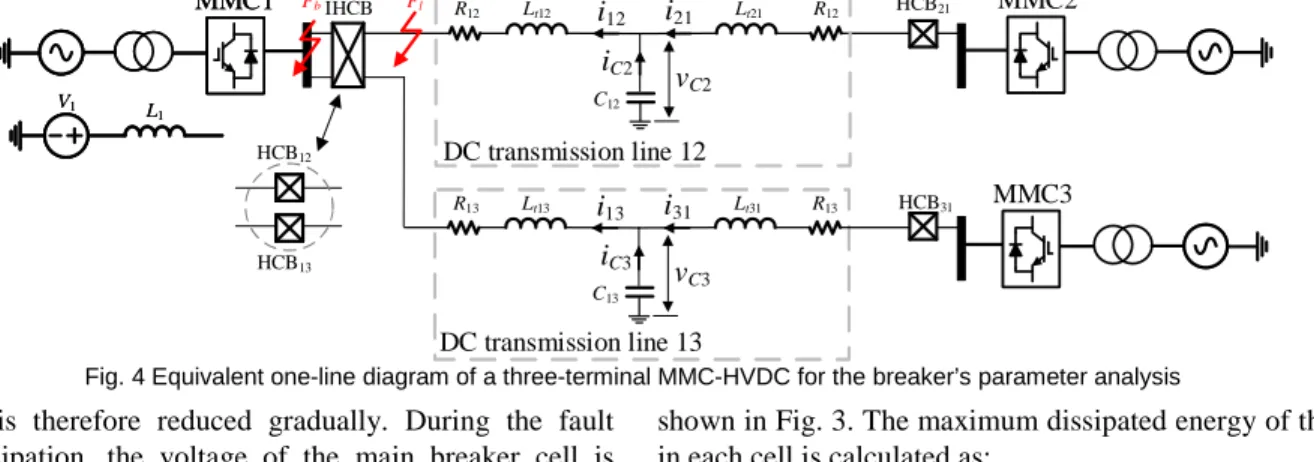
An equivalent one-line diagram of a three-terminal MMC-HVDC system, as shown in Fig. 4, is used to explain the design of breaker parameters. The design will consider the peak currents of the main breaker and load commutation switches, and the maximum dissipated fault energy of the MOV under the most severe fault current. Thus a DC bus fault Fb and a
transmission line fault Fl are used in the parameter design. The MMC converter is considered as a constant voltage source with an inductor L1 in series, see MMC1 in Fig. 4. L1 is the equivalent inductor of the arm inductors. Its value is 1/3 of the inductance of one arm inductor, because arm inductors on three phase units are in parallel. The transmission line is represented as a T-section RLC circuit. After a transmission line fault Fl occurs, the fault current flowing through the HCB is mainly contributed by MMC1, the fault current is expressed as: ) ( ) ( 1 12 1 1 12 12 t t L L V I t i CLR f (1)
Where V1 is the DC voltage of MMC1, I12 is the pre-faulted current of the transmission Line 12, LCLR12 is the inductance of current limiting reactor on Line 12, L1 is the equivalent arm inductor of MMC1.
For the HCB, the peak currents of the load commutation switch and the main breaker appear at t3 and t4 respectively, see Fig. 3, are calculated as:
) (3 1 12 1 1 12 12 t t L L V I I CLR LCS (2) ) (4 1 12 1 1 12 12 t t L L V I I CLR MB (3)
For the dissipated energy calculation of the MOV, its voltage is assumed to be constant at the protection level during t4-t5, as
shown in Fig. 3. The maximum dissipated energy of the MOV in each cell is calculated as:
2 ) (4 1 5 4 12 1 1 12 12 t t V t t L L V I E cell CLR MOV (4)
where Vcell is the voltage rating of the main breaker in each cell, also is the protection level of the MOV.
III. UNIDIRECTIONAL INTERLINK HYBRID HVDC CIRCUIT BREAKER
DC line faults can be interrupted by using only the unidirectional HCBs [7] [8]. The design that each HCB has one main breaker branch (see Fig. 5(a)) can be improved by sharing a main breaker branch between two HCBs. Two unidirectional main breaker branches can be replaced by one interlink main breaker branch, which 50% MOVs is reduced, as shown in Fig. 5(b). The fault current of Line 12 or Line 13 can be commutated to this main breaker branch to interrupt, therefore bidirectional main breaker cells are required.
The possibility of simultaneous faults occurring on different lines is extremely low, therefore, this situation has not been taken into account for the breaker design. And the unidirectional IHCB is unable to interrupt such faults. The descriptions for the operation principle, the parameter design and the MOV reduction are given below.
Taking the fault Fl occurred on Line 12 as an example, the operation principle of the unidirectional IHCB is given in Fig. 6. Before the fault, the load currents flow through the low-loss branches. A fault Fl occurs on Line 12 at t1 and is detected at t2, the fault current is then commutated from LCS12 to the main breakers, see Fig. 6 (a). At t3, the current of low-loss branch becomes zero, and UFD12 starts to open and completes action at t4. Then MB1 will open to interrupt the fault current. From
t4-t5, the fault energy is dissipated by the MOV1 and the fault current is reduced to 0 gradually, see Fig. 6 (c). From t3-t5, the LCS13 provides the path for the fault current flowing into the main breaker branch. After the fault is interrupted at t5, if restore is not required, the RCB12 is open to disconnect the Line 12 physically and protect the MOV from the overload. The UFD12 and LCS12 will then reclose to be a part of the interlink main breaker branch to protect Line 13 from the line fault, see Fig. 6 (d).
During the fault interruption t3-t5, see Fig. 6(b-c), LCS13 is the path for the fault current, which is commutated from the LCS12 to the main breakers, and the current i13 of Line 13. Its R12 Lt12 i12 i21 Lt21 R12 iC2 vC2 C12 R13 Lt13 i13 i31 Lt31 R13 iC3 vC3 C13 HCB31 HCB21 HCB12 HCB13 IHCB Fl Fb DC transmission line 12 DC transmission line 13 MMC2 V1 L 1 V1 L 1 MMC3 MMC1 MMC1
peak current ILCS13 appears at t4, when the fault current is interrupted by the main breakers. The peak current of the load commutation switch is ) ( ) (4 1 13 4 12 1 1 12 13 t t i t L L V I I CLR LCS (5)
Where i13(t4) is assumed to be equal to the load current I13 of Line 13. Because the influence of the fault on Line 13’s current
i1i is ignored due to the quick fault current interrupting and the current limiting reactors on Line 13.
The fault current keeps rising in the MB1 until it is interrupted at t4, the peak fault current of MB1 is:
) (4 1 12 1 1 12 1 t t L L V I I CLR MB (6)
The MOVs in main breaker cells dissipated the fault energy evenly, and for one MOV in each cell, its maximum dissipated energy is expressed as:
2 ) (4 1 5 4 12 1 1 12 t t V t t L L V I E cell CLR MOV (7)
After the fault is interrupted, the main breaker branch of the IHCB withstands the open-circuit DC voltage (V1) of MMC1. The voltage rating of the main breaker branch denoted as VMB, is 1.5V1. This interlink main breaker branch is composed of anti-series connected IGBT to achieve bidirectional interruption, the required numbers of IGBT modules and MOVs are: cell MB MOV IGBT MB IGBT V V n V V n 2 (8)
where VIGBT are the voltage ratings of one IGBT module. If two unidirectional HCBs are used, the voltage rating of the main breaker branch is same as that of the unidirectional IHCB, which is also 1.5V1. The numbers of IGBT modules and MOVs applied in two HCBs’ main breaker branches are:
2 2 cell MB MOV IGBT MB IGBT V V n V V n (9)
Compared (8) and (9), the number of IGBT modules are the same in the unidirectional IHCB and two unidirectional HCBs. However, only 50% MOVs are needed in the unidirectional IHCB.
IV. BIDIRECTIONAL INTERLINK HYBRID HVDC CIRCUIT BREAKER
The bidirectional HCB can be used to protect the system from not only line faults but also DC bus faults. When a DC bus fault occurs, the fault current of each line will be commuted from LCS to the main breaker branch before interrupted.
If a bidirectional IHCB would use the same main breaker branch as that of a unidirectional IHCB, see Fig. 7 (a), when a DC bus fault occurs, after both LSCs on Line 12 and Line 13 open, the LSCs would have to withstand the high DC voltage and the fault current cannot flow through the main breaker branch to the faulted bus. Therefore, one more branch is required to avoid overvoltage across LCSs and provide a path for the fault current commutation. A novel Y-connected interlink main breaker branch is thus proposed for the bidirectional IHCB to provide a path for the fault current after both LCSs open in order to interrupt the fault current. Its structure is shown in Fig. 7(b), an additional main breaker branch, (MB0 and MOV0) is added between the DC bus and the midpoint of the main breaker branch. The Y-connected main breaker branch also limits the number of IGBTs to be added.
Compared to using bidirectional HCBs, the number of IGBTs and MOVs are reduced by 25% by using the Y-connected branch. For either a line fault or a bus fault, the fault current will be commutated to the Y-connected interlink main breaker branch to interrupt.
M OV1 LCS12 UFD12 CLR12 RCB12 LCS13 UFD13 CLR13 RCB13 M B 1 LCS12 UFD12 CLR12 RCB12 LCS13 UFD13 CLR13 RCB13 MOV13 MB13 MOV12 MB12
(a) Two unidirectional HCBs (b) Unidirectional IHCB
Line 12
Line 13 Line 12
Line 13
MMCI MMCI
Fig. 5 Comparison between two unidirectional HCBs and the unidirectional IHCB (a) t1-t3 Line 12 Line 13 i12 i13 M O V 1 (b) t3-t4 Line 12 Line 13 i12 i13 M O V 1 (c) t4-t5 Line 12 Line 13 i12 i13 (d) after t5 Line 12 Line 13 i13 LCS12 UFD12 CLR12 RCB12 LCS12 UFD12 CLR12 RCB12 LCS12 UFD12 CLR12 RCB12 LCS12 UFD12 CLR12 RCB12 LCS13 UFD13 CLR13 RCB13 LCS13 UFD13 CLR13 RCB13 LCS13 UFD13 CLR13 RCB13 LCS13 UFD13 CLR13 RCB13 M B 1 M B 1 M B 1 M B 1 M O V 1 M O V 1 Fl Fl Fl MMCI MMCI MMCI MMCI
Fig. 6 Operation of the unidirectional IHCB for the transmission line fault LCS12 UFD12 CLR12 CLR13 RCB12 RCB13 Line 12 Line 13 M B 2 M B 1 MOV0 MB0 LCS13 UFD13 M O V 2 M O V 1
(b) Y-connected interlink main breaker branch
LCS12 UFD12 CLR12 CLR13 RCB12 RCB13 Line 12 Line 13 LCS13 UFD13
(a) Interlink main breaker branch
50% m ai n br e ake r br a nc h 50% m ai n br ea ke r b ra nc h MMCI MMCI
It is a cost-effective solution that the design of the bidirectional interlink hybrid DC circuit does not consider multiple faults occurring on the different lines at the same time. Because the presence of this fault situation especially under an HVDC grid using cables for the offshore application is extremely rare. The descriptions of the operation principle, the parameter design and reduction of the numbers of IGBT modules and MOVs are given below.
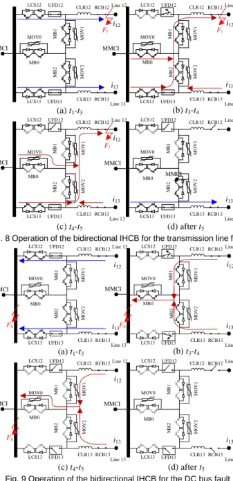
To interrupt the fault at a transmission line, the operation of an IHCB is shown in Fig. 8. Before the fault, the load currents flow through the low-loss branches. A fault occurs on Line 12 at t1, see Fig. 8 (a). When it is detected at t2, LCS12 is switched off and the fault current starts to be commutated into Y-connected main breakers. When the commutation process is finished at t3, UFD12 starts to open, see Fig. 8 (b). At t4, UFD12 is fully opened, the fault current will be interrupted by the Y-connected main breakers and the fault energy is dissipated over the MOVs 0, 1 and 2, see Fig. 8 (c). After the fault is
interrupted at t5, the RCB12 is open to disconnect the Line 12 and protect the MOVs from overload. The main breaker branches 0&2 are still available to protect Line 13, see Fig. 8 (d).
To interrupt the fault occurred on the DC bus Fb, the operation of the bidirectional IHCB is shown in Fig. 9. To test the breaker with the most severe fault, the load current is set to have the same direction as the fault current. Before the fault, the load current flows through the low-loss branch to the DC bus. The DC bus fault occurs at t1, see Fig. 9 (a). When it is detected at t2, both LCS12 and LCS13 are switched off and the fault currents of both Line 12 and Line 13 start to be commutated to the Y-connected main breakers. From t3, when the commutation process is finished, UFD12 and UFD13 start to open and complete the action at t4, see Fig. 9 (b). From t4, the fault current is interrupted by MBs 0, 1 and 2, and the fault energy will be dissipated by MOVs 0, 1 and 2, see Fig. 9 (c). After the fault is interrupted at t5, both RCB12 and RCB13 open to disconnect the faulty DC bus physically, see Fig. 9 (d).
Line faults are used to determine the specifications for the bidirectional IHCB. Thus, a line fault e.g. Fl in Fig. 4 is
selected.
During the fault interruption t3-t5, see Fig. 8(b-c), LCS13 is an alternative path for the fault current. the half fault current and the current i13 of Line 13 will pass through LCS13. Its peak current ILCS13 appears at t4, when the fault current is interrupted by the main breakers. The peak current of the load commutation switch is shown below:
( ) 0.5 (4 1) 12 1 1 12 4 13 13 t t L L V I t i I CLR LCS (10)
where the influence of the fault on Line 12’s current is ignored due to the quick fault current interrupting and the current limiting reactors on Line 13. i13(t4) is equal to the load current
of Line 13.
The main breaker 1 withstands the whole fault current, see Fig. 8(b). Its peak current appears at t4, when the fault current is interrupted. The peak current of the main breaker 1 or 2 is shown below: ) ( 4 1 12 1 1 12 1 t t L L V I I CLR MB (11)
The maximum dissipated energy of the MOV1 or MOV2 located on main are calculated as:
2 ) (4 1 5 4 12 1 1 12 1 t t V t t L L V I E cell CLR MOV (12)
As main breaker branch 0 need to withstand the high fault current from both Lines 12 and 13 caused by the DC bus fault. The DC bus fault is used to determine the parameter of the main breaker branch 0.
When a DC bus fault e.g. Fb in Fig. 4 occurs, the following equations of Line 12 or Line 13 are obtained using the KVL and KCL laws: j Cj j j tj CLRj j j v t V dt t di L L L t i R1 1( )( 1 1 ) 1( ) ( ) (13) ) ( ) ( ) ( ) ( 1 1 1 1 1 R i t v t dt t di L L j j Cj j j t j CLR (14) LCS12 UFD12 CLR12 CLR13 RCB12 RCB13 Line 12 Line 13 M B 2 M B 1 MOV0 LCS13 UFD13 i12 LCS12 UFD12 CLR12 CLR13 RCB12 RCB13 Line 12 Line 13 i13 M B 2 M B 1 MOV0 LCS13 UFD13 i12 LCS12 UFD12 CLR12 CLR13 RCB12 RCB13 Line 12 Line 13 i13 M B 2 M B 1 MOV0 MB0 LCS13 UFD13 LCS12 UFD12 CLR12 CLR13 RCB12 RCB13 Line 12 Line 13 i13 M B 2 M B 1 MOV0 MB0 LCS13 UFD13 (a) t1-t3 (b) t3-t4 (c) t4-t5 (d) after t5 M O V 2 M O V 1 M O V 2 M O V 1 M O V 2 M O V 1 M O V 2 M O V 1 i13 i12 MB0 MB0 Fl Fl Fl MMCI MMCI MMCI MMCI MMCI
Fig. 8 Operation of the bidirectional IHCB for the transmission line fault
LCS12 UFD12 CLR12 CLR13 RCB12 RCB13 Line 12 Line 13 M B 2 M B 1 MOV0 LCS13 UFD13 i12 LCS12 UFD12 CLR12 CLR13 RCB12 RCB13 Line 12 Line 13 i13 M B 2 M B 1 MOV0 LCS13 UFD13 i12 LCS12 UFD12 CLR12 CLR13 RCB12 RCB13 Line 12 Line 13 i13 M B 2 M B 1 MOV0 MB0 LCS13 UFD13 LCS12 UFD12 CLR12 CLR13 RCB12 RCB13 Line 12 Line 13 i13 M B 2 M B 1 MOV0 MB0 LCS13 UFD13 (a) t1-t3 (b) t3-t4 (c) t4-t5 (d) after t5 M O V 2 M O V 1 M O V 2 M O V 1 M O V 2 M O V 1 M O V 2 M O V 1 i13 i12 MB0 MB0 Fb Fb Fb MMCI MMCI MMCI MMCI
) ( ) ( t i dt t dv C Cj cj j (15)
)
(
)
(
)
(
1 1t
i
t
i
t
i
j
j
Cj (16)where j=2 or 3, Vj is the DC voltage of MMCj.
To simplify the fault current analysis, the total inductances on both sides of the capacitor C1j are supposed to be equal. The values of Lt1j and Ltj1 of the transmission lines should satisfy the relationship: j tj CLRj j t j CLR L L L L L 1 1 1 1 1 (17)
where L1j denotes the equivalent inductance between the faulted DC bus and the capacitor C1j and between the capacitor
C1j and MMCj.
The expression of vc is obtained by substituting (14-17) into (13): j Cj j j Cj j j Cj V dt t v d C L dt t dv C R t v 2 2 1 1 ) ( ) ( ) ( 2 (18)
Applying Laplace transformation to (18) yields
s V sv s v s C L v s sv C R s vCj( ) j j c( ) c(0) j j c( ) c(0) j 2 2 1 1 (19)where
v
c(
0
)
V
j is assumed due to the small value of R1j. The expression of vc(s) is obtained by arranging (19). 2 ) ( 1 5 . 0 ) ( 1 2 1 1 1 s R C s L C R s L C s V s v j j j j j j j j Cj (20)
Applying Laplace transformation to (14) and considering (20) yield:
2 ) ( 1 5 . 0 ) ( ) 0 ( ) ( 1 2 1 1 1 1 1 1 1 1 s R C s L C R s L C s V s i R i s si L j j j j j j j j j j j j j (21)The expression of i1j(s) is thus obtained from (21),
a s i b a s b b L a s s R V s i j j j j j (0) 1 ) 2 ( 1 ) 1 1 ( 1 5 . 0 ) ( 1 2 2 2 1 1 1 (22) where j j L R a 1 1 , 2 1 1 1 ) 2 ( 2 j j j j L R C L b and
i
1j(
0
)
I
1j which is the rated current in normal condition.The time-domain expression of i1j is obtained through inverse Laplace transform of (22):
at j t a j at j j j e bt I e b L e R V t i 2 1 1 1 1 sin( ) 1 ) 1 ( 1 5 . 0 ) ( (23)
As shown in (23), the fault current is determined by the rated current of both lines, the impedance of the transmission lines, the inductance of the CLRs and the arm inductor of converters. The fault current in the Y-connected main breakers keeps rising until the fault current is interrupted. The peak current in the main breaker 0 appears at t4:
3 2 4 1 0 ( ) i j MB i t I (24)The maximum dissipated energy of the MOV0 of each cell in this sub-branch is:
2 4 5 0 0 t t V I EMOV MB cell (25)
When a line fault is interrupted by the breaker, the
open-circuit voltage is the DC voltage (V1) of MMC1. When a bus fault is cleared by the breaker, the open-circuit voltage of is
j
j V
V 1 , Vj is the DC voltage of MMCj, and V1j is the voltage drop of Line 1j. Only the rated DC voltage V1 is considered to determine the voltage rating of the breaker as
j
j V
V
V1 1 .
For the bidirectional IHCB, two branches of the Y-connected main breaker branch share the open-circuit voltage V1. The voltage rating of each main breaker branch is VY-MB=
VMB/2=1.5V1/2=0.75V1. The numbers of IGBT modules and MOVs required for an interlink main breaker branch are:
3 5 . 0 2 3 5 . 0 cell MB MOV IGBT MB IGBT V V n V V n (26)
If two bidirectional HCBs are used, the open-circuit voltage for each main breaker branch is V1. The voltage rating VMB of each branch is 1.5V1. The numbers of IGBT modules and MOVs used in two main breaker branches are:
2 4 cell MB MOV IGBT MB IGBT V V n V V n (27)
Comparing (26) to (27), numbers of IGBT modules and MOVs are reduced by 25% by using the bidirectional IHCB.
V. SIMULATION VERIFICATION
The fault interruption capability of the IHCB and the HCB proposed in [2] are compared in a three-terminal MMC-HVDC system. The positions of the line fault and the DC bus fault is shown in Fig. 4. The DC transmission lines are represented as pi-sections in series. For the purpose of only testing the circuit breaker devices, the breakers (IHCB, HCB12 and HCB13 see Fig. 3) are set to start to open at a fixed current [17], i.e. 2kA in this study. The commutation time from the load commutation switch to the main breakers is 0.25 ms [17]. The UFD is simulated as a resistor switch with 2 ms [16] opening delay. The main data of test system is summarized in Table I.
The load commutation switch consists of 3×3 IGBT modules [17]. Its current and voltage ratings are fulfilled by 2×2 IGBT modules. The rest of the IGBT modules are used as redundancy. The structure of the LCS is shown in Table II. The
TABLEI
MAIN DATA OF TEST SYSTEM
Items Value
One π-section (20 km) of overhead line
0.228 Ω, 18.7 mH,
0.246 μF
Length of Line 12 and Line 13 100 km Voltage control in MMC1 320 kV Power control in MMC 2-3 900 MW
Arm inductor 50 mH
SM capacitor 8 mF
Number of SMs 100
IGBT RCE0=0.49 mΩ VCE0=1.22 V
Diode Ron=0.39 mΩ FVD=1.09 V
CLR 100 mL
Main breaker cells 120 kV
voltage rating of each main breaker cell is 120 kV. The numbers of IGBT modules used in the main breakers of the IHCB and HCB are summarized in Table III. The data of 4.5-kV StakPak IGBT module [19] are used in the simulation.
A. Unidirectional interlink hybrid HVDC breaker
During normal operation, MMC2 and MMC3 receive 900 MW respectively from MMC1. The currents in transmission Line 12 and Line 13 are both 1.42 kA.
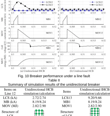
A line fault Fl, that occurs at 0.5s on Line 12, is applied to test the fault interruption performance of the unidirectional IHCB, shown in Fig. 6. During the fault interruption, the performance of the unidirectional IHCB is shown in Fig. 10 (a). The peak currents of the load commutation switch (see LCS13) and the main breaker are 9.16 kA and 8.19 kA, both appearing at 5.025s. After the fault current is interrupted by the main breakers at 5.025s, the fault energy is dissipated by the MOV and the fault current drops to 0 kA at 0.5083s. During this period, the voltage of each cell is limited at 120 kV and then drops to the normal DC voltage 80 kV. The total dissipated energy of the MOV in one cell is 2.82 MJ.
For comparison, the performance of the unidirectional HCB12 for the same fault interruption is shown in Fig. 10(b). The fault current of Line 12 will not flow through LCS13 located on Line 13, therefore the peak current of the load commutation switch is 2.72kA appearing at 5.025s. The performance of other components in unidirectional HCB is exactly the same as that in the IHCB.
From the simulation results of both the unidirectional HCB and IHCB, the peak current of the load commutation switch and the main breaker, and the maximum dissipated energy of the MOV in one cell are summarized in Table II. These values show good agreement with those calculated from (2-4) and (5-7) as summarized in Table II.
The current rating of the normal load commutation switch is 8kA which cannot be used in the unidirectional IHCB for 9.16 kA peak current. 4×4 IGBT modules are used for double current ratings of the load commutation switch in the unidirectional IHCB. 4×2 IGBT modules ensure the 16 kA maximum load current and sufficient voltage stress. The rest of the IGBT modules are used as the redundancy. Its structure is drawn in Table II.
B. Bidirectional interlink hybrid HVDC breaker
Both the line fault Fl and the DC bus fault Fb that occur at 0.5 s respectively are used to test the fault interruption performance of the bidirectional IHCB. According to the analysis in the parameter design of the bidirectional IHCB, the line fault Fl is selected to test the parameters of the load commutation switch and the main breaker branch, LCS1 and MB1 in this case. The
DC bus fault Fb is for testing the main breaker branch 0. During normal operation, MMC2 and MMC3 receive 900 MW each from MMC1. The currents in transmission Line 12 and Line 13 are both 1.42 kA.
A line fault Fl, that occurs at 0.5s on Line 12, is applied to test the fault interruption performance of the bidirectional IHCB, shown in Fig. 8. During the line fault interruption, the performance of the bidirectional IHCB is shown in Fig. 11(a). The peak currents of the load commutation switch, LCS13 and the main breaker, MB1, are 5.10 kA and 8.19 kA, both appearing at 5.025s. The total dissipated energy of the MOV1 in one cell is 2.82 MJ.
The performance of the bidirectional HCB for the same line fault interruption is shown in Fig. 11(b). The peak current of the load commutation switch is 2.72kA appearing at 5.025s. The performance of the main breaker branch in bidirectional HCB is exactly the same as the main breaker branch 1 of the IHCB. A bus fault Fb, that occurs at 0.5s, is applied to test the fault interruption performance of the bidirectional IHCB, shown in Fig. 9. During normal operation, MMC2 and MMC3 send 900 MW each to MMC1. The power transportation is reversed to keep the same direction between the load current and the fault current. The currents of Line12 and Line13 are both 1.42 kA.
During the fault interruption, the performance of the bidirectional IHCB is shown in Fig. 12(a). The peak current of the main breaker 0 is 8.57 kA occurs at the 0.5025, when the
Fig. 10 Breaker performance under a line fault Table II
Summary of simulation results of the unidirectional breaker Items on Line 12 Unidirectional HCB simulation/calculation Items Unidirectional IHCB simulation/calculation LCS (kA) 2.72/2.74 LCS13 9.20/9.66 MB (kA) 8.19/8.24 MB1 8.19/8.24 MOV (MJ) 2.82/2.90 MOV1 2.82/2.90 Structure of LCS Structure of LCS TABLE III Main data of test system
Items Two unidirectional HCBs Unidirectional IHCB Two Bidirectional HCBs Bidirectional IHCB Main breaker branch 2 (480 kV each) 1 (480 kV each) 2 (480 kV each) 3 (240 kV each)
Main breaker cell 8 4 8 6
MOV 8 4 8 6
IGBT modules 216 216 432 324
Y-connected main breakers interrupt the fault current. The maximum dissipated energy of the MOV0 in one cell is 3.22 MJ. During the DC bus fault interruption and the post-fault condition, the oscillations of the fault current and the cell voltage occurred because of the large equivalent capacitance of the transmission line.
The performance of the bidirectional HCB located on Line 12 for the same DC bus fault is shown in Fig. 12(b).
As shown in Fig. 11 and Fig. 12, the fault currents through each line caused by the DC bus fault is smaller than that from line faults due to the current limiting reactors located on both line ends and the equivalent inductance of the transmission line. The peak current and maximum dissipated energy of the load commutation switches and the main breaker branches 1&2 in the bidirectional IHCB are lower than that in the case of the line fault. Thus, ratings of those components are determined by line fault interruption requirement. And the ratings of main breaker branch in the bidirectional IHCB is determined by the DC bus fault interruption requirement because the fault currents of both
lines will flow through this branch.
From the simulation results of both the bidirectional HCB and IHCB, the peak currents of the load commutation switch and the main breaker, and the maximum dissipated energy of the MOV of each cell under both the line and bus faults are summarized in Table IV. These values show good agreement with those calculated from (2-4), (10-12), and (24-25) as summarized in Table IV. The peak current of the LCS of the bidirectional IHCB is higher than that of the bidirectional HCB. The normal load commutation switch with 8 kA current rating can still be used for the IHCB, because the peak current of its LCS is 5.10 kA. In terms of the peak current and maximum dissipated energy, the main breaker branches 1&2 of the bidirectional IHCB have the same parameter as those in the bidirectional HCB. The parameters of the main breaker branch 0 are slightly higher than that in the bidirectional HCB.
VI. CONCLUSION
Novel interlink hybrid DC circuit breakers (IHCB) for unidirectional and bidirectional interruption are proposed with an aim of reduced sizes and costs of the DC circuit breakers.
For a unidirectional IHCB, an interlink main breaker branch is shared by two low-loss branches to achieve the same function as that of two unidirectional hybrid DC circuit breakers (HCBs). For a bidirectional IHCB, a novel Y-connected main breaker branch is proposed for the both line and DC bus fault current interruption. The current ratings, energy dissipation capability, and required numbers of IGBTs and MOVs of the IHCBs have been determined by considering the peak fault currents and the maximum energies dissipation. Mathematic analyses have been achieved to support the design. Comparing to HCBs, the number of MOVs of the main breaker branch of the unidirectional IHCB is reduced by 50% and the numbers of IGBT modules and MOVs of the main breaker branch of the bidirectional IHCB are reduced by 25%. The current ratings of LCSs used in both unidirectional and bidirectional interlink hybrid DC circuit breakers must be increased to withstand the fault current.
The fault current interruption performance of the main breaker branches of both bidirectional and bidirectional IHCBs are compared to the HCBs through simulations. The proposed IHCBs can interrupt the fault currents at the same speed. The IHCB design is able to meet all the requirements for peak fault currents and maximum dissipated energies.
The multiple faults are not considered in the design of the IHCB because the presence of multiple faults occurring on different transmission lines at the same time is extremely rare. In the case of such faults, back-up protection would be used.
REFERENCE
[1] J. Hafner and B. Jacobson, “Proactive hybrid HVDC breakers- A key innovation for reliable HVDC grids”. CIGRE Conf., Bologna, Italy, Sep. 2011, pp. 1-8.
[2] M. Callavik, A. Blomberg, J. Jafner and B. Jacobson, “The hybrid HVDC breaker: An innovation breakthrough enabling reliable HVDC grids,” ABB Grid Systems, Technical Report, 2012.
[3] W. Grieshaber, and L. Violleau, “Development and test of a 120 kV direct current circuit breaker,” Gigre 2014, Paris, 2014, pp. 1-11
Fig. 11 Breaker performance under a line fault
Fig. 12 Breaker performance under a DC bus fault Table IV
Summary of simulation results of the bidirectional breaker Items on Line 12 bidirectional HCB simulation/calculation Items bidirectional IHCB simulation/calculation LCS (kA) 2.72/2.74 LCS13 5.10/5.54 MB (kA) 8.19/8.24 MB1 MB0 8.19/8.24 8.7/9.14 MOV (MJ) 2.82/2.90 MOV1 2.82/2.90 MOV0 3.22/3.77
[4] W. Zhou et al., "Development and test of a 200kV full-bridge based hybrid HVDC breaker," 17th European Conference on Power Electronics
and Applications (EPE'15 ECCE-Europe), Geneva, Switzerland, 2015,
pp. 1-10.
[5] Cigre Working Group A3/B4.34, “Technical requirements and specifications of state-of-the-art HVDC switching equipment,” Cigre
Technical Brochure 683, 2017.
[6] W. Wen, Y. Huang, Y. Sun, J. Wu, M. Al-Dweikat and W. Liu, “Research on current commutation measures for hybrid DC circuit breakers”, IEEE
Tran. Power Delivery, vol. 31, no. 4, pp. 1456-1463, August 2016.
[7] R. Derakhshanfar, T. U. Jonsson, U. Steiger and M. Habert, “Hybrid HVDC breaker- A solution for future HVDC system,” Cigre 2014, Paris, France, 2014
[8] A. Jehle, D. Peftitsis and J. Biela, "Unidirectional hybrid circuit breaker topologies for multi-line nodes in HVDC grids," 2016 18th European
Conference on Power Electron. and Applicat. (EPE'16 ECCE Europe),
Karlsruhe, Germany, 2016, pp. 1-10.
[9] F. Xu, H. Yu, and et al., “Topology, control and fault analysis of a new type HVDC breaker for HVDC systems,” 2016 IEEE PES Asia-Pacific Power Energy Eng. Conf, Xi’an, China, 2016, pp. 1-10.
[10] J. Liu, N. Tai, C. Fan and S. Chen, "A Hybrid Current-Limiting Circuit for DC Line Fault in Multiterminal VSC-HVDC System," IEEE Trans. Ind.
Electron., vol. 64, no. 7, pp. 5595-5607, July 2017
[11]G. Liu, F. Xu, Z. Xu, Z. Zhang and G. Tang, “Assembly HVDC breaker for HVDC grids with modular multilevel converters”, IEEE Trans. Power
electron., vol. 32, no. 2, pp. 931-941, February 2017.
[12] L. Mackay and E. Kontos, “DC switch yard and method to operate such a DC switch yard,” World Intellectual Property Organization Patent WO2017034408 A1, Mar. 2, 2017.
[13] E. Kontos, T. Schultz, L. Mackay, L. Ramirez-Elizondo, C. Franck, and P. Bauer, “Multi-Line Breaker for HVDC Applications,” IEEE Trans.
Power Deliv., vol. 8977, no. c, pp. 1–8, 2017.
[14] R. Majumder, S. Auddy, B. Berggren, G. Velotto, P. Barupati, and T. U. Jonsson, “An Alternative Method to Build DC Switchyard with Hybrid DC Breaker for DC Grid,” IEEE Trans. Power Deliv., vol. 32, no. 2, pp. 713–722, 2017.
[15] A. Mokhberdoran, D. V. Hertem, N, Silva, H. Leite, and A. Carvalho, “Multi-port hybrid HVDC circuit breaker,” IEEE Trans. Ind. Electron., vol. pp, no. 99, pp. 1-1, 2017.
[16]P. Skarby, and U. Steiger, “An ultra-fast disconnecting switch for a hybrid HVDC breaker-technical breakthrough,” 2013 Cigre Canada Conf., Calgary, Alberta, Sep. 2013.
[17]A. Hassanpoor, J. Hafner and B. Jacobson, “Technical Assessment of load commutation switch in hybrid HVDC breaker,” IEEE Trans. Power
Electron., vol. 30, no. 10, pp. 5393-5400, Oct. 2015.
[18]R. Derakhshanfar, T. U. Jonsson, U. Steiger and M. Habert, “Hybrid HVDC breaker- A solution for future HVDC system,” Cigre 2014, Paris, France, 2014.
[19] “5SNA2000K450300 data sheet,” ABB Semiconductor, Lenzburg, Switzer- land, Mar. 2013. [Online]. Available: http://www.abb.com
Chuanyue Li (M’17) received the B.Eng. degrees from both Cardiff University, UK and North China Electric Power University, China, in 2013 and the Ph.D. degree from Cardiff University, UK, in 2017.
He is a post-doc at the Laboratory of Electrical Engineering and Power Electronics (L2EP), Lille, France. His research interests include HVDC control and protection, and power electronics.
Jun Liang (M’02-SM’12) received the B.Sc. degree from Huazhong University of Science and Technology, Wuhan, China, in 1992 and the M.Sc. and Ph.D. degrees from China Electric Power Research Institute, Beijing, China, in 1995 and 1998, respectively.
From 1998 to 2001, he was a Senior Engineer with China Electric Power Research Institute. From 2001 to 2005, he was a Research Associate at Imperial College, London, U.K.. From 2005 to 2007, he was a Senior Lecturer at the University of Glamorgan, Wales, U.K.. Currently, he is a Professor at the School of Engineering, Cardiff University, Wales, U.K. His research interests include FACTS devices/HVDC, power system stability and control, power electronics, and renewable power generation.
Sheng Wang (M’17) was born is Quzhou, Zhejiang, China. He received the B.Eng. degrees from both Cardiff University, UK and North China Electric Power University, China, in 2011. He received the Ph.D. degrees from Cardiff University, UK in 2016.
From 2013 to 2014, he was also a Research Assistant with Cardiff University, UK. Currently, he is a Research Associate at the School of Engineering, Cardiff University, Wales, U.K. His research interests include HVDC control and protection, HVDC devices, power electronics, and renewable power generation.