Prototype environment for controller
programming in the IEC 61131-3 ST language
1Dariusz Rzońca, Jan Sadolewski, and Bartosz Trybus
Rzeszów University of Technology, Division of Informatics and Control, ul. Wincentego Pola 2, 35-959 Rzeszów, Poland
{drzonca, js, btrybus}@prz-rzeszow.pl
Abstract. A prototype compiler of the ST language (Structured Text), its operation and internal structure is presented. The compiler is a principal part of CPDev engineering environment for programming industrial controllers according to IEC 61131-3 standard. The CPDev is under development at Rzeszów University of Technology. The compiler generates an universal executable code as final result. The code can be interpreted on different platforms by target-specific virtual machines. Sample platforms include AVR, ARM, MCS-51, PC.
1. Introduction
The main goal of the IEC 61131-3 standard introduced in 1998 was to increase quality of programmable controllers software [5]. By defining special programming languages and procedures it frees designers from using general purpose languages like C, focusing instead on implementation of control algorithms.
This paper describes a prototype environment for programming industrial controllers according to the IEC 61131-3 standard. The environment, called
CPDev (Control Program Developer), is built around the Microsoft .NET
Framework [8] using C# language. Its main component is the compiler which transforms programs written in ST, one of five IEC 61131-3 languages [5], to an universal executable code. ST is a high level language, similarly to Pascal, Ada and C. Among the other IEC languages, ST seems the most flexible, so it was chosen as the base for CPDev. Specification of the executable code has been prepared in such a way, that the resulting code can be executed on different target platforms, so small microcontrollers or larger microprocessors, via target-specific virtual machines. Therefore the code is called universal. The machines operate as interpreters of this code. Generally speaking, the approach resembles the concept of Java virtual machines designed for implementation on different platforms [6]. The CPDev basic machine is written in industry standard C for easy adaptation for various C compilers.
2.
IEC 61131-3 standard and ST language
The IEC 61131-3 standard defines five programming languages - LD, IL,
FBD, ST and SFC. Instruction List IL and Structured Text ST are text
languages, Ladder Diagram LD, Functional Block Diagram FBD and
Sequential Function Chart SFC are graphical. LD and IL are fairly simple, so
appropriate mainly for small applications. FBD, ST and SFC are recommended for medium- and large scale projects. John's and Tiegelkamp’s book [12] is a good source to learn IEC programming. According to [9], familiarity with the languages by engineering staff looks as follows: LD 90%, FBD 60%, IL 35%, ST 30%, SFC 15%. Computer and control engineers with experience in structural programming usually prefer ST.
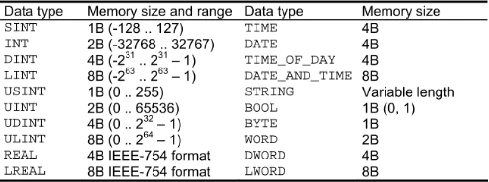
Common components of the five languages are names (identifiers), data types, constants and variables. Twenty elementary data types of IEC 61131-3, together with memory sizes and ranges in the CPDev environment, are
shown in Tab. 1. In practice BOOL, INT, REAL and TIME are the most
common. Examples of corresponding constants are FALSE, 13, -4.1415 and
T#1m3s. The IEC standard defines three access levels to variables, namely LOCAL, GLOBAL and ACCESS. LOCAL variables are available in the program
or function block. GLOBALs can be used in the whole project, but programs or
blocks must declare them as EXTERNAL. ACCESS variables exchange data
between different systems.
Table 1. Elementary data types of IEC 61131-3, their size and range in the CPDev environment
Data type Memory size and range Data type Memory size
SINT 1B (-128 .. 127) TIME 4B
INT 2B (-32768 .. 32767) DATE 4B
DINT 4B (-231 .. 231 – 1) TIME_OF_DAY 4B LINT 8B (-263 .. 263 – 1) DATE_AND_TIME 8B
USINT 1B (0 .. 255) STRING Variable length
UINT 2B (0 .. 65536) BOOL 1B (0, 1)
UDINT 4B (0 .. 232 – 1) BYTE 1B
ULINT 8B (0 .. 264 – 1) WORD 2B
REAL 4B IEEE-754 format DWORD 4B
LREAL 8B IEEE-754 format LWORD 8B
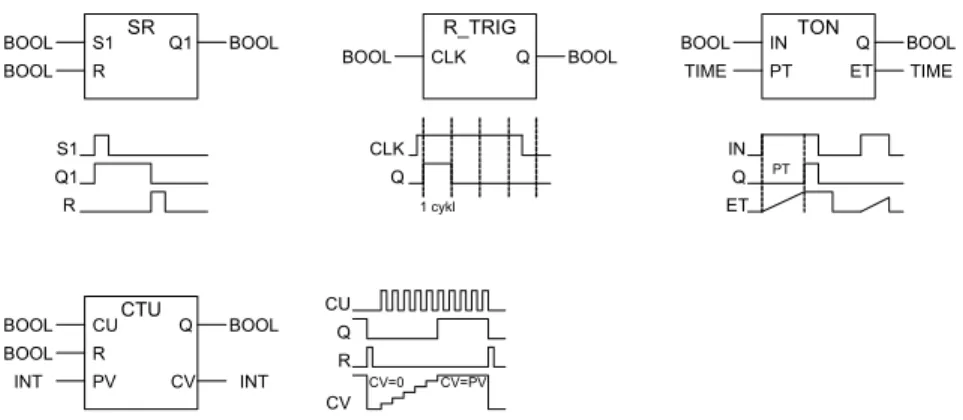
Functions, function blocks and programs are components of the IEC projects. Function blocks, designed for multiple reuse in different parts of the program, are essential. Typical block involves input and output variables, and employs values from previous executions. The IEC standard defines a small set of standard blocks, such as flip-flops, edge detectors, timers and counters. Four of them are shown in Fig. 1.
Of the five IEC languages, ST is particularly suitable for implementation of nonstandard or complex algorithms. Most development systems recommend
ST as a default language for defining user function blocks. Therefore it has been chosen as a base language for the CPDev environment.
SR S1 R Q1 BOOL BOOL BOOL R_TRIG CLK Q BOOL BOOL TON IN PT Q BOOL TIME BOOL TIME ET S1 R Q1 CLK Q 1 cykl IN ET Q PT CTU CU R Q BOOL BOOL BOOL INT CV PV INT CU Q R CV CV=0 CV=PV
Fig. 1. IEC 61131-3 standard blocks: SR flip-flop, rising edge detector R_TRIG, timer TON, counter CTU
Initial part of an ST program involves declarations of variables and block
instances written between VAR and END_VAR keywords. The declarations are
followed by sequence of program instructions. The instructions contain expressions which involve operators such as: bracket, function call, negation, arithmetical operators, comparison, boolean operators (in descending
priority). Similarly as in Pascal, the symbol := denotes assignment. An
example for starting or stopping an engine has the following form:
engine := (start OR engine) AND NOT stop AND NOT alarm;
Four types of control instructions are available in ST:
− conditional branches: IF, CASE,
− loops: FOR, WHILE, REPEAT,
− brake or stop: RETURN, EXIT, END,
− function block call.
Example of the last one may look as follows. After declaring Timer1: TON
as an instance of the TON block (Fig. 1), one can call it by
Timer1(IN:=engine1, PT:=t#2.5s);
Output Q of the timer can be assigned to a variable in the following way
engine2:=Timer1.Q;
Alternatively, both input and output parameters may be included in a single call, i.e.
3. The
CPDev
environment
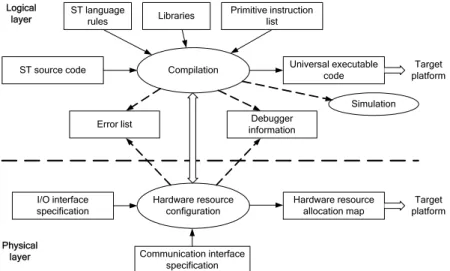
Engineering environments are integrated tools for development, debugging, deployment and maintenance of control software. Structure of the CPDev environment is shown in Fig. 2. It involves separate logical and physical layers what simplifies programming and compiling for different hardware platforms.
Compilation Universal executable code ST source code
Error list informationDebugger ST language rules Primitive instruction list Libraries Simulation Logical layer Hardware resource configuration Target platform I/O interface specification Communication interface specification Hardware resource
allocation map platformTarget Physical
layer
Fig. 2. Structure of the CPDev development system
ST compiler is an essential part of the logical layer. It translates ST programs into the universal executable code interpreted later by a virtual machine on the target platform. The compiler employs ST language rules, function block libraries and a set of primitive instructions implemented in the virtual machine. Single ST instruction is translated into one or several primitive instructions. Logical layer is also responsible for debugging information, deployment, simulation and list of errors.
Hardware resource configuration at the physical layer involves specifications of memory, input/output interfaces and communications. The specifications describe memory types and areas, inputs and outputs, addresses and types of communication channels, failure indicators, etc. Hardware allocation map (Fig. 2) is a table, which assigns symbolic names from the ST program to physical addresses. By using it, the compiled code can be assembled for a particular platform to create final, universal executable code. Hardware platforms differ only in hardware allocation maps while compiled code is identical (before assigning addresses).
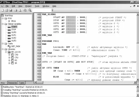
Fig. 3. User interface of the CPDev system
Three basic windows of the CPDev user interface are shown in Fig. 3 [11]. They involve:
− trees of project structure, hardware configuration and program resources -
left part, interchangeable,
− program in ST language - center,
− message list - bottom.
The windows can be moved across the screen or minimized, frames
adjusted and the contents scrolled. Window of the StartStop project (Fig. 3)
contains the program PRG1 which consists of CTD, CTU, RS, SR function
blocks and the main task DEF_TASK. The main program involves global
variables START, STOP to OUT3 with addresses %MX0000, %MX0001 up to
%MX000F, respectively (directly represented variables). According to IEC
61131-3, the %MX prefix indicates a variable stored in memory (M) and
occupying a single bit (X). The first instruction of the program activates output
OUT0, similarly as control of the engine in Sec. 2. Next, if OUT0 is on, the
outputs OUT1, OUT2 and OUT3 are activated every 2s. The PRG1 program is
executed every 200ms.
Hardware configuration tree, which would replace the project structure (left window) represents hardware of the controller (inputs/outputs, communication modules etc.), or a group of controllers if a distributed system is designed. Program resource tree contains lists of global and system variables, linked
libraries and list of user-defined variable types (arrays, structures, etc.).
TASK_CYCLE and TIME_COUNT are system variables.
In practice a typical ST program is a sequence of function block calls, where outputs from the previous block become inputs to the next one. Two libraries are available for the user in the CPDev system, i.e.:
− IEC 61131-3 standard blocks (Sec. 2 and Fig. 1),
− general purpose blocks (flip-flops, signal processing, on/off control, PID,
set point generator, positioner, drive control, sequencer and some others).
Table 2. Programs of TON, SR and R_TRIG standard function blocks
Function block: TON Function blocks: SR, R_TRIG
FUNCTION_BLOCK TON VAR stime: TIME; END_VAR VAR_INPUT IN: BOOL; PT: TIME; END_VAR VAR_OUTPUT Q: BOOL; ET: TIME; END_VAR FUNCTION_BLOCK SR VAR_INPUT S1: BOOL; R: BOOL; END_VAR VAR_OUTPUT Q1: BOOL; END_VAR Q1 := S1 OR (NOT R AND Q1); END_FUNCTION_BLOCK IF NOT IN THEN Q := FALSE; ET := t#0ms; stime := CUR_TIME(); ELSE IF NOT Q THEN ET := CUR_TIME() - stime; IF ET >= PT THEN Q := TRUE; ET := PT; END_IF END_IF END_IF END_FUNCTION_BLOCK FUNCTION_BLOCK R_TRIG VAR_INPUT CLK: BOOL; END_VAR VAR_OUTPUT Q: BOOL; END_VAR VAR CLKp: BOOL := FALSE; END_VAR Q := CLK AND NOT CLKp; CLKp := CLK; END_FUNCTION_BLOCK
Additional blocks can be programmed by the user and stored in additional
libraries. To create a new block, one should begin with FUNCTION_BLOCK
keyword in the upper window (Fig. 3). Blocks from all linked libraries can be accessed. Simple programs of three standard blocks are presented in Tab. 2.
The flip-flop SR and edge detector R_TRIG are self-explanatory (CLKp
denotes previous value of CLK). Operation of TON has been illustrated in
Fig. 1. The input PT denotes preset time, while the output ET is elapsed time beginning from activation of the input IN. ET is evaluated as the difference
between current value of the system time counter (value returned by
CUR_TIME() function) and the value stime read when rising edge at IN has
appeared.
The CPDev environment uses the XML format for libraries, programs, configurations etc. as proposed in [13].
4.
ST compiler components
The ST compiler contains three basic components, i.e. scanner, parser and
code generator (Fig. 4). Character
stream
SCANNER
Token list PARSER Mnemonic code CODE
GENERATOR Executable format ST language source file Sequence of ST tokens and their categories Collection of identifiers descriptions and their code (VMASM) Portable binary file
Fig. 4. ST compiler components
Main task of the compiler is to convert character stream into an executable
format. This is done in three steps. First, lexical analyzer (scanner) analyzes
a stream of characters in the input ST language source file and decomposes it into tokens. Category of the tokens is also determined according to Tab. 3. The tokens are stored in a list passed to the parser (Fig. 4).
Table 3. Token types recognized by the compiler
Type name Token example Type name Token example
identifier PRG1 integer constant 50
keyword FUNCTION operator +
typed constant DINT#1722211 delimiter ,
comment (*assign outputs*) directive (*$READ*)
real constant 18.32 white space
string constant 'Temperature: ' invalid character \
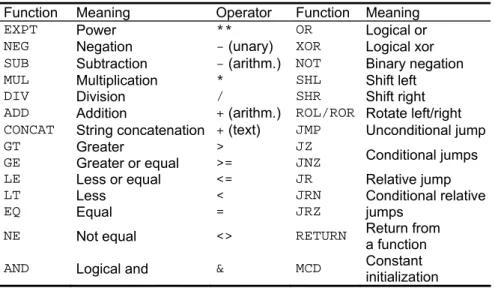
In the second step, the parser recognizes the tokens and checks validity of token constructions. It ignores comments and white spaces. The parser utilizes built-in elementary data types, operators, and a set of primitive instructions of virtual machine. Examples of the instructions are shown in Tab. 4. Derived data types [5,11], functions and function blocks stored in additional libraries are also parsed (if needed). The parser translates the token list into an identifier collection and creates an intermediate mnemonic code called VMASM (Virtual Machine Assembler). This code uses a special text format for storing primitive instructions and their operands. Finally, the code generator produces a portable executable code for the virtual machine.
Modules of the mnemonic code can be merged together and converted into the executable format.
Table 4. Primitive instructions of the virtual machine
Function Meaning Operator Function Meaning
EXPT Power ** OR Logical or
NEG Negation - (unary) XOR Logical xor
SUB Subtraction - (arithm.) NOT Binary negation
MUL Multiplication * SHL Shift left
DIV Division / SHR Shift right
ADD Addition + (arithm.) ROL/ROR Rotate left/right
CONCAT String concatenation + (text) JMP Unconditional jump
GT Greater > JZ
GE Greater or equal >= JNZ Conditional jumps
LE Less or equal <= JR Relative jump
LT Less < JRN
EQ Equal = JRZ
Conditional relative jumps
NE Not equal <> RETURN Return from
a function
AND Logical and & MCD Constant
initialization
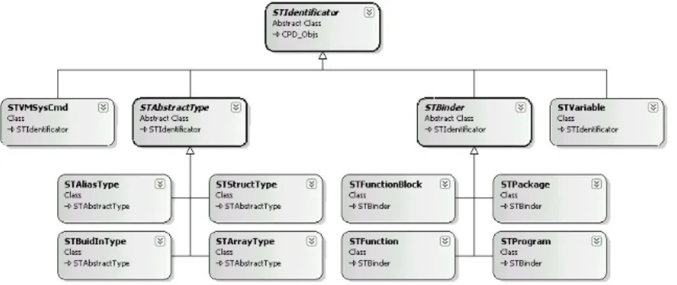
The essential components of the compiler are designed as classes in the C# language [1,3]. The parser is built according to top-down scheme with syntax-directed translation [4]. Each unit of the ST language is encapsulated into an object of corresponding class (Fig. 5). The classes inherit from an
abstract STIdentificator class. During compilation, identifiers are
collected into lists. The lists employ predicates for finding appropriate identifiers and eliminate the need for hash tables (normally used while developing compilers). There is a list of global identifiers and local lists which store identifiers of functions, function blocks, programs, etc. Identifiers in a list are checked for uniqueness. When identical names are found compilation is stopped and error reported. If local identifier hides a global one, the compiler produces an information.
The parser generates text sequence of primitive instructions. Each instruction is represented by a mnemonic followed by operand names. Code generator replaces mnemonics and variable names with appropriate number identifiers (indexes). While processing an instruction, the generator extracts some information from libraries, e.g. operand size, type and passing method. The number identifier can be interpreted as a pointer to variable or as immediate value. Instructions for the virtual machine resulting from
compilation are represented by instances of VMInstruction class. The
operand list is also stored as a member of this class. By using lists of operands typical problems with fixed-size operand tables are avoided.
Fig. 5. Object representation of ST language units
5. Compilation
stages
A project in CPDev, stored in the XML format, can contain global variables, functions, function blocks, programs, task and libraries. The following example, illustrated by Figs. 6, 7, shows the process of compiling a project for
a function block TON (see Tab. 2). First, project items are merged into a single
source file (Fig. 6, center). This source code, with definition of TON, will be
processed to result in the universal executable code for the virtual machine. Project Project items: -global variables -functions -function blocks -programs -tasks -libraries join Source ST file FUNCTION_BLOCK TON VAR stime: TIME; END_VAR VAR_INPUT IN: BOOL; PT: TIME; END_VAR VAR_OUTPUT Q: BOOL; ET: TIME; END_VAR IF NOT IN THEN Q := FALSE; ET := t#0ms;
stime := CUR_TIME(); ELSE IF NOT Q THEN ET := CUR_TIME() - stime; IF ET >= PT THEN Q := TRUE; ET := PT; END_IF END_IF END_IF END_FUNCTION_BLOCK compilation Mnemonic code (VMASM) 001 NOT ?IF?B00A6, IN 002 JZ ?IF?B00A6, :IF?B00A7 003 MCD Q, #/01, #/00 004 MCD ET, #/04, #/00000000 005 CUR_TIME STIME 006 JMP :IF?E00AB 007 :IF?B00A7 008 NOT ?IF?B00AC, Q 009 JZ ?IF?B00AC, :IF?E00AB 010 CUR_TIME ?FCL00AF
011 SUB ET, ?FCL00AF, STIME
012 GE ?IF?B00B1, ET, PT 013 JZ ?IF?B00B1, :IF?E00AB 014 MEMCP Q, ?L_TRUE, #/0100 015 MEMCP ET, PT, #/0400 016 :IF?E00AB 017 RETURN STEP 1 STEP 2
Fig. 6. Compilation process - steps 1 and 2
In the first step the scanner splits input character stream into tokens. Then, the token list is passed to the parser, which removes white spaces and
comments. The parser also checks for invalid or unknown tokens and eventually reports an error, giving the file name and position of the bad token. If there are no syntax errors, the compilation begins. In the example of Fig. 6,
the token FUNCTION_BLOCK is recognized as a keyword. The next token
(TON) is treated as a new identifier and stored in the global identifier list as an
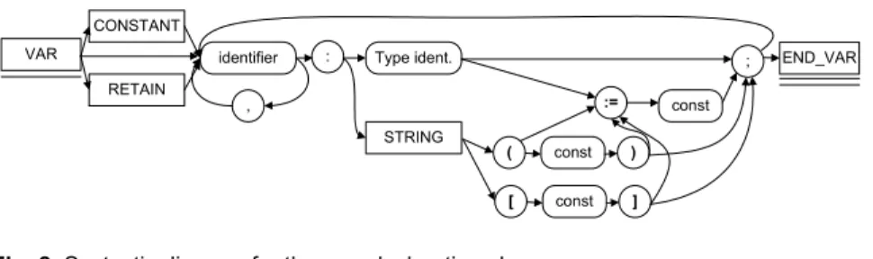
object of STFunctionBlock type (Fig. 5). The declaration clauses beginning
with VAR are interpreted by the parser according to its syntactic diagram
(Fig. 8) [10]. At this stage the compiler also defines memory areas for input parameters, outputs variables, and local variables.
Library configuration file (LCF) <function name="GE" vmcode="110B" return="BOOL">
<args>
<arg no="0" type="TIME"/> <arg no="1" type="TIME"/> </args>
<comment>Check if first argument is greater or equal than second argument</ comment>
</function>
consolidation
Universal executable code address: function operand address: next operands 002A: 05 10 0E 00 002E: 04 00 0030: 1C 02 0E 00 0034: 4E 00 0036: 1C 15 09 00 003A: 01 00 003C: 1C 15 0A 00 0040: 00 19 0042: 1C 17 00 00 0046: 1C 00 84 00 004A: 05 10 14 00 004E: 09 00 0050: 1C 02 14 00 0054: 84 00 ...
Virtual machine memory model .CODE 05 10 0E 00 04 00 ... .END .DATA 00 00 1F 01 00 00 ... .END dump Output files -data segment -code segment -information for simulation -compilation report STEP 3 Mnemonic code (VMASM) 001 NOT ?IF?B00A6, IN 002 JZ ?IF?B00A6, :IF?B00A7 003 MCD Q, #/01, #/00 004 MCD ET, #/04, #/00000000 005 CUR_TIME STIME 006 JMP :IF?E00AB 007 :IF?B00A7 008 NOT ?IF?B00AC, Q 009 JZ ?IF?B00AC, :IF?E00AB 010 CUR_TIME ?FCL00AF 011 SUB ET, ?FCL00AF, STIME 012 GE ?IF?B00B1, ET, PT ...
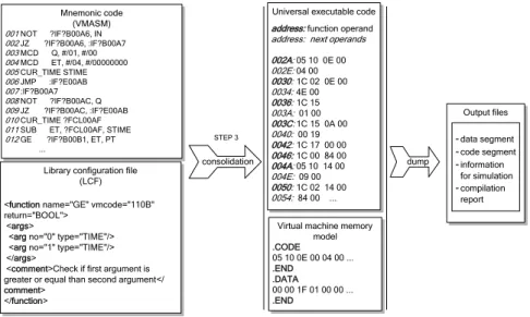
Fig. 7. Compilation process - step 3 and object dump
Compilation of the function block code section begins when next token does not match any of the declaration clauses. In the example the keyword
IF indicates a conditional instruction. Therefore the text up to the keyword
THEN is assumed to be a boolean expression. The result of evaluation of this
expression is stored in an auxiliary local variable ?IF?B00A6, so with the
name preceded by quotation mark ?. This mark is used for every element of
the code which has not been explicitly given any name. The expression
between IF and THEN is converted into the lines 001-002 of the mnemonic
code (right box in Fig. 6). Line 001 contains primitive instruction NOT that
stores result in ?IF?B00A6 variable. Line 002 contains conditional jump JZ
dependent on ?IF?B00A6 to the label :IF?B00A7. If NOT returns FALSE
(zero in ?IF?B00A6), the lines 003–004 initialize the output Q with FALSE and
ET with T#0ms. Line 005 calls the system function CUR_TIME (current system
time) and stores returned value in stime. Unconditional jump JMP in the line
contain similar code executed when NOT returns TRUE. Subtraction SUB in
the line 011 involves the variable ?FCL00AF which now keeps the current
time, and the initial stime. The label :IF?B00A7 in the line 007 and
:?IF?E00AB in 016 follow from ELSE and END_IF, respectively. RETURN at
the end causes virtual machine to finish execution of the function block.
VAR CONSTANT RETAIN identifier , Type ident. STRING : := ; END_VAR const ( const ) [ const ]
Fig. 8. Syntactic diagram for the VAR declaration clause
In the third step the final executable code is created. The compiler links the compiled code with all required modules (Fig. 7). The mnemonic code is translated into binary executable by replacing:
− mnemonic function names with number identifiers (opcodes),
− variable names with data area indexes,
− label names with code addresses (absolute or relative).
The last step involves Library Configuration File (LCF; Fig. 7, lower left).
This is an XML file with additional information required during compilation such as mnemonics of the primitive functions and opcodes, argument order and types. It can also contain some target-specific information, like big- or little-endian byte order. Resulting universal executable code is shown in the upper right box in Fig. 7. As seen, 1009 (hex) is the opcode of the first
instruction GT. The others follow accordingly.
6. Virtual
machine
Software deployment process can be represented as in Fig. 9. The universal executable code is transferred to a target controller where it is executed by the virtual machine.
Controller executive program I/O interface Universal executable code Virtual machine On-line tests (commissioning) Hardware resource
allocation map Communication interface
PC
Fig. 9. Software deployment process for different hardware platforms
RUNmode ? Reading inputs Execution Task - program 1 - program 2 - . . . Writing outputs YES NO Next cycle Cycle time
Fig. 10. Phases of the virtual machine cycle
As indicated before, the machine is specific for a particular microprocessor and operates as an interpreter. Code and data are stored in two different memory areas (similarly as in Harvard architecture processors). The virtual machine is an automaton operating according to Fig. 10. Following IEC 61131-3 standard, a task consists of programs executed successively. Universal code of the compiled program contains identifiers of primitive instructions and their operands (Fig. 7). While executing a program, the machine fetches successive instruction, decodes it, fetches the operands, and finally executes the instruction. The machine monitors time cycles of the tasks and alarms if timeout appears. It also triggers input/output procedures responsible for external variables (Fig. 10).
I/O functions Instruction interpreter Memory access Platform-dependent Universal Stack
emulation Data type handling
Time & clock Multitasking
Fig. 11. Virtual machine’s internal structure
The virtual machine code consists of universal and platform dependent modules (Fig. 11). The machine maintains program counter with the index to currently executed instruction and with base address to memory area with variables. Together with stack emulation, this allows for multiple and concurrent calls of functions and function blocks (which employ internal variables). The machines provide relatively short execution times due to similarity of primitive instructions (Tab. 4 earlier) to assemblers of typical microprocessors, as well as indexing techniques used for interpretation [10].
Device memory Instruction select ... Adding ... Reference reg. Internal memory ... 01 22 00 08 2A 07 ... Code segment ... 00 08: 21 D2 ... 00 41: 1A 57 ... Data segment
Fig. 12. Memory segments of the virtual machine
The virtual machine instructions and their operands are stored in the code segment of memory (Fig.12). It is read–only memory, so none of primitive instructions can modify the contents. The data segment contains variables and constant values, function blocks and programs. This segment can be accessed directly or indirectly by special registers. Internal memory contains stacks, registers and the interpreter code. The internal memory cannot be accessed by primitive instructions. Virtual machine is able to execute multiple instances of programs.
Modular structure of the virtual machine simplifies implementation in different hardware platforms. Usually only the platform-dependent modules have to be rewritten or modified. Code of the universal modules remains unchanged (the source code must be compiled for the target CPU anyway). The platform-dependent modules (Fig. 11) interface the machine to particular hardware, executing VM requests to low-level procedures. For example the
Time&clock employs timer interrupt to compute task cycle and set timeout flag. If real-time clock chip is available, it can trigger events that occur at
regular, long intervals (e.g., every Sunday midnight). I/O functions provide
interface to analog and binary inputs and outputs, and to communication fieldbus or network. The multitasking module is optional, since it employs multitasking mechanisms provided by host operating system. In such arrangement, task instances use private copies of global variables to avoid
conflicts (so-called process image mechanism).
The virtual machine has been written in the industry standard C language, so it can be directly adapted to different microprocessors. If limited hardware resources are available, an XML configuration file specifies simplified version of the machine. For example, one can limit the number of elementary data types or define a subset of primitive instructions to be used. Till now, the machines for AVR, MCS-51 and PC platforms have been developed. Another one for ARM-core based microprocessors is being considered.
a) b)
RS-485 USB PC CPDev SCADA inputs outputs SM5 SM4 SMCFig. 13. a) SMC controller, b) simple SMC-based system
First applications of the CPDev has already been tested in cooperation with LUMEL Zielona Góra company. The SMC programmable controller (Fig. 13a) and appropriate firmware including special version of the virtual machine have been developed. The controller employs AVR ATmega 128 CPU [2]. SMC operates as a central unit of mini-distributed system in control, measurement and monitoring applications. Usually it is equipped with SM1 – SM5 input/output modules (Fig. 13b), but other devices can be connected to RS-485 interface using industry standard MODBUS RTU protocol [7].
7. Summary
A compiler of IEC 61131-3 Structured Text language, basic component of the CPDev development system, has been presented in the paper. ST programs are translated into specially designed universal executable code. Target-specific virtual machine can execute such code on a controller CPU.
Although more advanced environments are available from commercial manufacturers, e.g. Step7 from Siemens, Control Builder from ABB, Concept from Schneider, they can handle only manufacturers’ hardware. The CPDev is oriented towards small-and-medium scale manufacturers and supports, or will support, a range of popular platforms, such as AVR, MCS-51, ARM or PC. It is being created having in mind both generality and openness, which means that it can be adjusted to specific needs.
8. References
1. Appel A., Palsberg J.: Modern compiler implementation in Java. Second edition. Cambridge University Press. (2002)
2. ATmega 128 Datasheet. Atmel 2007. [Online]. Available: http://www.atmel.com/dyn/resources/prod_documents/doc2467.pdf (current November 2007)
3. C# Language Specification - [Online]. Available: http://msdn2.microsoft.com/en-us/vcsharp/aa336809.aspx (current November 2007)
4. Cooper K., Torczon L.: Engineering a Compiler. Morgan Kaufmann, San Francisco. (2003)
5. IEC 61131-3 standard: Programmable Controllers - Part 3, Programming Languages. IEC. (2003)
6. Lindholm T., Yellim F.: Java Virtual Machine Specification Second Edition. Java Software, Sun Microsystems Inc. (2004)
7. Modicon MODBUS Protocol Reference Guide. MODICON, Inc., Industrial Automation Systems, Massachusetts (1996). [Online]. Available: www.modbus.org/docs/PI_MBUS_300.pdf
8. MS .NET Framework Developer's Guide - [Online]. Available: http://msdn2.microsoft.com/en-US/library/aa720433.aspx (current November 2007)
9. Pietrusewicz K.: Biggest study of Polish PLC controllers market. Control Engineering Polska, 26-38. (February 2007) (in Polish).
10. Rzońca D., Sadolewski J., Trybus B.: IEC 61131-3 standard ST compiler into universal executable code. In: Real-Time Systems. Methods and Applications, WKŁ, Warsaw, 189-198. (2007) (in Polish).
11. Stec A., Świder Z., Trybus L.: Functional characteristic of the prototype system for embedded systems programming. In: Real-Time Systems. Methods and Applications, WKŁ, Warsaw, 179-188. (2007) (in Polish).
12. John K.H., Tiegelkamp M.: IEC 61131-3: Programming Industrial Automation Systems. Berlin Heidelberg, Springer-Verlag. (2001)
13. XML Formats for IEC 61131-3 ver. 1.01 - Official Release. [Online]. Available: www.plcopen.org/
Dariusz Rzońca is an assistant at the Department of Informatics and Control, Rzeszów University of Technology. He received B.Sc. in mathematics in 2002, and M.Sc. in computer engineering in 2004. His research focuses on coloured Petri nets and communication in microprocessor systems.
Jan Sadolewski is an assistant at the Department of Informatics and Control,
Rzeszów University of Technology. He received M.Sc. in computer engineering in 2006. His interests are in C, C#, Delphi, Java, and Assembly 8086. He currently works on modern programming languages and compiler implementations.
Dr. Bartosz Trybus is an assistant professor at the Department of
Informatics and Control, Rzeszów University of Technology. He received Ph.D. in computer engineering in 2004 from AGH University of Science and Technology, Cracow. His research focuses on real-time systems and design techniques for control applications.