Post-tensioned CFRP strap elements for civil engineering
applications
Thomas Keller
Swiss Federal Institute of Technology Lausanne, EPFL, Switzerland
ABSTRACT: Two applications of post-tensioned CFRP strap elements recently developed at the Composite Construction Laboratory (CCLab) of the Swiss Federal Institute of Technology Lausanne (EPFL) are presented. The first application concerns post-tensioned non-laminated CFRP straps used for the strengthening of existing concrete flat slabs against punching shear. Four strap elements are installed crosswise around the column in predrilled openings and are anchored and post-tensioned from the bottom side of the slab. Laboratory experiments on eight full-scale flat slabs showed that, although CFRP is a brittle material, the strap post-tensioning assured a ductile system behavior. A punching shear resistance increase of more than 100% was obtained. The second application concerns post-tensioned laminated CFRP straps used for permanent ground and rock anchors. They consist of a CFRP tendon with a two-strap end on the ground side, embedded in a prefabricated high-strength grout cylinder. The ground anchor is post-tensioned to 60% of the 1000 kN design load, which was obtained from pull-out experiments.
1 CFRP STRAPS FOR PUNCHING SHEAR STRENGTHENIG
Flat concrete slabs without shear reinforcement are susceptible to brittle punching failure (Kinnunen et al. 1960). In recent years, it has become evident that many flat slabs, particularly those built between the 1960s and 80s, have insufficient punching shear reinforcement and therefore require strengthening. A post-tensioned strengthening system against punching shear, composed of flexible carbon fiber-reinforced (CFRP) straps has been developed. In predrilled and precut openings, four unbonded CFRP straps are installed crosswise, which can easily be anchored and post-tensioned from the lower side, see Fig. 1. Post-tensioning significantly improves the system efficiency due to the partial unloading of the slab.
Non-laminated CFRP straps, as described in Lees et al. (2002) and produced by Carbo-Link, Fehraltdorf (Switzerland), were used. The dimensions and mechanical properties of one tape layer (consisting of Toray T700 fibers and a thermoplastic Nylon PA12 matrix) and of the multi-layer strap system are summarized in Table 1. Three strap configurations were used: straps of 25, 33, and 50 loops, the latter presenting the maximum available size. The strength of the straps, Pu, as well as the post-tensioning levels, , and post-tensioning forces, P0, of the straps are summarized in Table 2.
The CFRP straps were arranged and anchored in two different ways: in an open configuration, as shown in Fig. 1, using two steel end-anchors, or in a closed configuration, as shown in Fig. 2, using steel end-pins and a turnbuckle to post-tension the strap. Both systems exhibit advantages and disadvantages: the open system requires a precise strap length while the closed systems allow for compensation in the turnbuckle. In the latter case, however, the system is less stiff due to the
longer strap length. Steel deviators were used on the top in the open and on the top and bottom in the closed configuration. In the latter case, therefore, adhesive bonding of anchoring devices was not necessary. The diameter of all steel pins and deviators was between 22.5 and 40mm.
Eight square full-scale flat slabs of dimensions 3.2×3.2m2 and thickness h=0.26m were fabricated, two reference slabs (P1/2), four slabs in open (So1-So4) and two slabs in closed configuration (Sc1/2).
Figure 1. Crossed open non-laminated CFRP straps for punching strengthening.
Figure 2. Crossed closed non-laminated CFRP straps for punching strengthening. Table 1. CFRP strap properties (5% fractile values / mean values).
CFRP t [mm] b [mm] A [mm2] f p [MPa] Ep [GPa] Strap (tape) 0.125 30.0 3.75 2100/2460 132/132 Strap (system: 2×25/33/50 loops) 6.25/8.25/12.5 30.0 188/248/375 1660/1820 132/132 Table 2. Overview of denominations and experimental matrix
(A: brittle punching failure; B: ductile concrete crushing during steel yielding). Slab Anchor A
[mm2] P[kN] u (nom.) [%] (eff.) [kN] P0 (eff.) f[MPa]c F[kN] max Failure mode
P1 - - - – – 30.3 896 A P2 - - - – – 31.3 1017 A So1 open 375 683 46 317 39.9 1990 B So2 open 248 450 48 217 40.7 1801 B So3 open 188 341 66 225 40.3 1778 B So4 open 375 683 15 103 40.9 1771 B Sc1 closed 375 683 5 32 51.5 1200 A Sc2 closed 375 683 41 278 56.6 1839 B
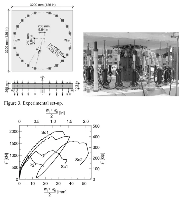
The slabs were placed on a center column, on a steel supporting plate of 0.25×0.25m2. The loading system consisted of 20 hydraulic cylinders of 150kN capacity each, arranged in a circle of 3.00m diameter around the slab center, see Fig. 3. Loading was manually applied at 100kN intervals in load-control mode at a rate of approximately 50kN/min. A spring manometer allowed the simulation of displacement control and enabled the post-peak response to be captured.
Figure 3. Experimental set-up.
Figure 4. Load-deflection response of slabs P2, So1, So2, Sc1.
The typical load-deflection responses of one slab of each configuration are shown in Fig. 4, together with a two-cycle response of So2. The weaker axis deflections (average of deflections w1 and w6 of both sides), at 1380mm distances from the center point, are shown. The deflections of the stronger axis were around 85% of those of the weaker axis.
The non-linear responses up to around 800kN depended on the post-tensioning force. The higher the post-tensioning force, the later concrete cracking and corresponding stiffness loss were
observed. Subsequent to cracking the slope of all slabs developed similarly. Without any warning, sudden punching failure occurred in slab P2 at 1017kN. Slab P1 behaved similarly to P2, the ultimate load being slightly lower. A similar unannounced punching failure occurred in slab Sc1 at 1180kN. Subsequent to a significant drop of the load, however, the slab could be slowly reloaded up to a second, slightly higher peak of 1200kN. Slabs So1/So2 behaved differently. Failure did not occur suddenly, a plateau was approached and a ductile failure through concrete crushing and yielding of the upper steel reinforcement developed slowly up to the ultimate load of 1990kN in the case of So1. So2 was unloaded from the plateau at 1801kN, exhibiting a residual deflection of 13 mm, and was then reloaded. Again a plateau was reached; however, the resulting ultimate load of 1573 kN, was only 87% of the first cycle maximum load. The remaining slabs, So3, So4 and Sc2, behaved similarly. So1 and Sc2, in particular, which were strengthened with the same straps and post-tensioning levels, showed similar results, although the open system was applied in the former and the closed system in the latter case. From the structural point of view, the closed system therefore did not show any beneficial effect.
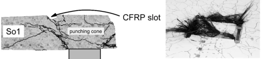
Figure 5. Punching failure of slab So1 and strap failure in So3.
Details of the failure modes are shown in Fig. 5. In slabs showing ductile failure, cracks delimiting the punching cone were much steeper than in the reference slabs. One series of cracks always went from the top slot of the CFRP strap down to the support edge (at angles of around 60°) and a 2nd series of cracks developed at 30-48°, almost perpendicular to the CFRP strap which crossed the crack. In one slab only, So3, failure of the two straps of the stronger axis occurred, at a 2nd slightly lower peak however, see Fig. 5.
All ultimate loads, Fmax, are given in Table 2; the highest ultimate load was obtained for slab So1, which had the highest post-tensioning force while the lowest values were obtained for slabs P1/2 and Sc1 without any or the lowest post-tensioning forces. Strap post-tensioning of at least 15% and more led to a ductile behavior exhibiting a first peak load, a subsequent plateau and a second peak load, although the CFRP material systems were brittle. The ultimate load of the unreinforced slabs could be increased by 77-118% in the ductile cases via a redistribution of forces from the concrete to the strap systems. Further results and details can be found in Keller et al. (2013).
2 CFRP STRAPS FOR GROUND ANCHORS
FRP tendons are increasingly used to replace conventional steel tendons in ground anchors, taking advantage of their high strength-to-weight ratio and good corrosion resistance. Conceptually similar to steel strands, FRP strands were developed by twisting a certain number of small-diameter wires. A high load-bearing capacity could be achieved by forming FRP cables assembled from several strands (Benmokrane et al. 1997).To anchor the tendon on the air and ground sides, mechanical or bonded anchors are commonly used (Schmidt et al. 2012). However, two problems exist in these types of CFRP anchors, which could lead to a premature failure in the anchor and thus not allow to exploit the full tendon capacity: 1) high shear and through-thickness stress concentrations existing at the anchorage are critical due to the anisotropic properties of CFRP
fibers; 2) uneven load distributions among the assembled strands or rods occur, i.e. some of them were obviously less loaded compared to others (Wang et al. 2015).
A simpler and much more material-tailored anchorage method, based on strap ends, was developed to anchor CFRP tensile elements (Winistoerfer 1999). A new application of this strap anchorage method for permanent post-tensioned CFRP ground anchors was recently proposed (Fan et al. 2017), which consists of a CFRP tendon with a laminated two-strap end on the ground side, embedded in a prefabricated high-strength grout cylinder confined with CFRP rings, as shown Fig. 6. The main purpose of the rings is to deviate the spreading forces at the embedded strap ends into the cylinder’s axial direction and not to increase the grout strength. The grout cylinder is thus stepwise axially loaded by the axial components of the spreading forces. The ground anchor with the prefabricated anchor body can be 20–80 m long and coiled, then transported to the construction site, inserted into the borehole, anchored by injecting fresh standard (normal-strength) grout and finally post-tensioned to 60% of the design load (1000kN).
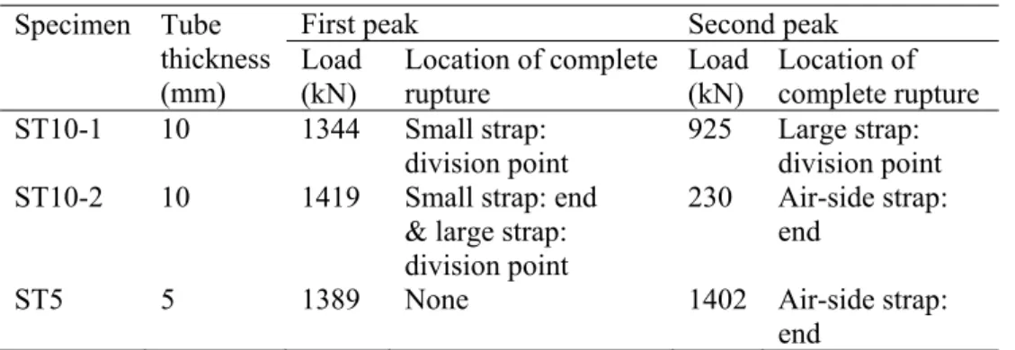
Figure 6. CFRP two-strap anchor specimen: (a) schematic (dimensions in [mm]); (b) photo. Table 3. Summary of experimental results.
Specimen Tube thickness (mm)
First peak Second peak
Load (kN) Location of complete rupture Load (kN) Location of complete rupture ST10-1 10 1344 Small strap: division point 925 Large strap: division point ST10-2 10 1419 Small strap: end
& large strap: division point
230 Air-side strap: end
ST5 5 1389 None 1402 Air-side strap:
end
To validate the new anchor concept, anchor specimens were pulled out from mortar cylinders confined by steel tubes of different thicknesses which simulated different confinement levels of the rock mass. The laminated CFRP tendons were produced by Carbo-Link; they were composed of unidirectional UTS50 F24 24k 1600tex D carbon fibers impregnated with XB 3515 AD1571 ACC1573 epoxy resin; the fiber volume fraction was 60±2%. The two-strap end was embedded in a 1060-mm-long high-strength grout body with inclined and corrugated surface on the ground side, as shown in Fig. 6. A non-shrink sand/cement high-strength grout (SikaGrout-212 provided by Sika Schweiz AG, Switzerland) was used. Three 150-mm-long and 2-mm-thick identical CFRP confinement rings were installed around the two strap ends and the division point. They consisted of the same materials as the tendon and were fabricated by filament winding. The anchor body geometry was designed to fit in boreholes with a minimum diameter of 130 mm.
The prefabricated anchor body was inserted into a 1200-mm-long steel tube, simulating a rock mass. Three anchor specimens with two different tube thicknesses were investigated in order to study the influence of the rock stiffness on the load-bearing capacity of the CFRP anchor; an overview of the experimental series is shown in Table 3. A normal-strength sand/cement grout, commonly used for steel ground anchors (Sika normal rock anchor mortar, provided by Sika Schweiz AG), was used to fill the space between prefabricated anchor head and steel tube. The pull-out experiments were conducted on a Trebel 10MN machine, as shown in Fig. 7. The loading was applied to the bottom side in displacement-control mode at a rate of 1 mm/min. After four load cycles up to 100, 300, 500 and 700 kN respectively, the anchor was loaded up to failure.
Figure 7. Experimental set-up (dimensions in [mm]) and load vs pull-out displacement responses.
All specimens exhibited similar load vs pull-out displacement responses in the failure cycle up to a first peak, as shown in Fig. 7. An almost linear response was observed, except a slight nonlinear behavior at the beginning; the latter was attributed to a progressive debonding at the CFRP/grout interface, which also caused a small residual displacement after the four initial load cycles up to 700kN, as shown in Fig. 7 for anchor ST5. The three anchors reached similar loads at the first peak, indicating that the confinement level had low influence on the load-bearing capacity of the anchor. At this first peak, delamination was observed in the visible air-side straps in anchors ST10-1/2, while no damage was recognizable in ST5. After the first peak, the load dropped and increased again to a second peak in all specimens where partial or complete rupture of the air-side strap occurred in anchors ST10-2 and ST5 respectively, see Fig. 8. The obtained peak loads are listed in Table 3.
After failure, the specimens were cut into two halves in the strap plane, see Fig. 8. All anchors exhibited rupture in the embedded CFRP tendons; no compression failure in the grout parts was observed, except small cracks located in the normal-strength grout at the end of the CFRP rings, see Fig. 8(a). In anchor ST10-1, the large and small straps were completely separated from the rod at the division point on one side, while partial rupture or delamination occurred in the semicircles of the small or large straps, see Figure 8(b). In anchor ST10-2, complete rupture was visible at the division point of the large strap and in the semicircle of the small strap. Furthermore, partial rupture or delamination occurred in the semicircle of the large strap and the division point of the small strap, see Figure 8(c). In anchor ST5, complete rupture occurred in the semicircle of the large strap and partial rupture in one straight part of the large and at the end of the small strap; no damage was visible at the division point. The failure sequence in the embedded straps could be derived based on the observations made during the experiments, strain measurements on the CFRP tendon and CFRP rings, and the post-failure pattern in Fig. 8; a summary of this failure sequence is shown in Table 3.
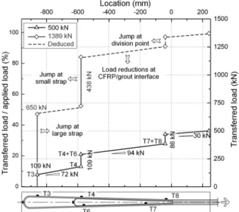
Figure 9. Load transfer along embedded straps at 500 and 1389 kN in anchor ST5.
The load transfer from the embedded CFRP tendon components to the high-strength grout of anchor ST5, at 500kN (pre-damage phase) and 1389kN (first peak), is shown in Fig. 9. The load jumps at the different positions were calculated based on measured tensile strains; the load transfer between the jumps, derived from the strain differences between the latter, were caused by the bond and friction at the CFRP/grout interface. At 500kN, the large and small straps transferred only 109kN
(21.7% of 500kN) each to the grout while 196kN (39.2%, = 72+94+30kN) were transmitted at the CFRP/grout interface, and the remaining 86kN (17.2%) were transferred at the division point. In contrast, the load transfer by the large and small straps at 1389 kN was much higher: 650kN (46.8%) and 438kN (31.5%) respectively (78.3% in total), corresponding to a load-distribution ratio of 0.6:0.4. In anchor ST10-2, 500kN (35.9%) and 344kN (24.7%) were transferred by the large and small straps at 1389kN (in total 60.6%), exhibiting a load-distribution ratio of 0.6:0.4 identical to ST5. The transferred loads were 23.1 and 21.5% respectively lower than in anchor ST5, indicating that more load was transferred by friction and at the division point, which also corresponded to the later strap activation due to the higher confinement.
3 CONCLUSIONS
Two applications of CFRP strap tensile elements were presented. In both applications, the strap ends provided an excellent material-tailored anchoring of the post-tensioned elements. In the strengthening elements against punching shear of concrete flat slabs, non-laminated straps provided the required flexibility and enabled the required small radii of curvature at the deviation points. In the ground anchors tendons, laminated straps were implemented to obtain the required stiffness during installation. Nevertheless, their flexibility remained sufficient to coil them during transportation.
4 REFERENCES
Benmokrane, B., Xu, H., and Nishizaki, I., 1997, Aramid and carbon fibre-reinforced plastic prestressed ground anchors and their field applications, Canadian Journal of Civil Engineering, 24/6, 968-985. Fan, H., Vassilopoulos, A. P., Keller, T., 2017, Pull-out behavior of CFRP ground anchors with two-strap
ends, Composite Structures, 160, 1258-1267.
Keller, T., Kenel, A., Koppitz R., 2013, Carbon fiber-reinforced polymer punching reinforcement and strengthening of concrete slabs, ACI Structural Journal, 110/6, 919-927.
Kinnunen, S., and Nylander, H., 1960, Punching of concrete slabs without shear reinforcement,
Transactions of the Royal Institute of Technology, No. 158, Stockholm, Sweden, 1960.
Lees, J. M., Winistörfer, A. U., and Meier, U., 2002, External prestressed CFRP straps for the shear enhancement of concrete, ASCE Journal of Composites for Construction, 6/4, 249-256.
Schmidt, J. W., Bennitz, A., Täljsten, B., Goltermann, P., and Pedersen, H., 2012, Mechanical anchorage of FRP tendons–A literature review, Construction and Building Materials, 32, 110-121.
Wang, X., Xu, P., Wu, Z., and Shi, J., 2015, A novel anchor method for multitendon FRP cable: manufacturing and experimental study, Journal of Composites for Construction, 19/6, 04015010. Winistoerfer, A. U., 1999. Development of non-laminated advanced composite straps for civil engineering

![Figure 7. Experimental set-up (dimensions in [mm]) and load vs pull-out displacement responses](https://thumb-us.123doks.com/thumbv2/123dok_us/10939891.2982661/6.892.129.683.384.661/figure-experimental-set-dimensions-load-pull-displacement-responses.webp)