UCLA
UCLA Electronic Theses and Dissertations
TitleRobust and Energy Efficient Hardware-Oriented Security for IoT Systems and Applications Permalink https://escholarship.org/uc/item/5wb1f99d Author Gu, Hongxiang Publication Date 2019 Peer reviewed|Thesis/dissertation
UNIVERSITY OF CALIFORNIA Los Angeles
Robust and Energy Efficient Hardware-Oriented Security for IoT Systems and Applications
A dissertation submitted in partial satisfaction of the requirements for the degree Doctor of Philosophy in Computer Science
by
Hongxiang Gu
©Copyright by Hongxiang Gu
ABSTRACT OF THE DISSERTATION
Robust and Energy Efficient Hardware-Oriented Security for IoT Systems and Applications
by Hongxiang Gu
Doctor of Philosophy in Computer Science University of California, Los Angeles, 2019
Professor Miodrag Potkonjak, Chair
Internet of Things (IoT) is a revolutionary network that is envisioned to connect physical entities to the cyber world. IoT technology has fundamentally changed how we interact with our world. Worldwide spending on IoT is forecast to reach $745 Billion in 2019, and it is expected that investments in the technology will maintain double-digit growth rate for years to come.
Despite wide adoption and strong anticipation in the technology, two major obstacles heavily constrained the further development in IoT, respectively security and energy chal-lenges. From the security perspective, the entire lifecycle of an IoT device could potentially be vulnerable to various types of attacks. Since many devices are deployed in an insecure environment, attackers could gain unauthorized access to the exposed hardware, which in-validates many security assumptions made in traditional security research. From the energy perspective, many IoT devices are incapable of affording traditional cryptographical protec-tion due to low energy and computaprotec-tion budget. Energy efficiency is therefore crucial for designs and establishments of IoT.
To address IoT security problems, we explore and propose novel hardware-oriented se-curity primitive designs and optimization techniques in this thesis. We first investigate the vulnerabilities of physically unclonable function (PUF), a popular low power hardware se-curity primitive used in IoT devices, through the creation of a hardware emulation platform
using programmable delay lines (PDL). To address vulnerabilities in PUFs, we propose a novel security primitive, Interconnected PUF Network (IPN), that interconnects small seg-ments of strong PUFs in a reconfigurable network, limiting the single-bit prediction accuracy to as low as 53.19% against a wide range of modeling attacks. We demonstrated that the interconnections in an IPN can be optimized to maximize output randomness and stability using our proposed evolution-strategies-based algorithm. Looking beyond PUF-based secu-rity, we designed content-driven injective functions (CRIF) that rearrange compositions of hardware injective functions based on previous messages, providing secure message encryp-tion/decryption between IoT devices.
Facing the energy challenges, we propose “computing while racing” technique that re-duces 40.4% of area overhead and 7.69% of power when implementing arbiter PUF and arbitrary logic on field-programmable-gate-arrays (FPGAs). This is achieved through en-coding digital signals in analog forms and achieves a high percentage of hardware sharing, suggesting resource sharing could potentially be a promising direction for power/energy re-duction in IoT devices.
Eventually, we propose two practical IoT applications. We first design a device anomaly detection utilizing the inconsistency in environmentally sensitive PUF challenge-response pairs. We show that our detector is more flexible and more power-efficient compared to state-of-the-art system monitors. Secondly, we demonstrate that our proposal of PUF-assisted group key management protocol securely protects IoT group communications while reducing global energy consumption by 47.3% compared to cryptographic key management solutions.
The dissertation of Hongxiang Gu is approved.
Milos D. Ercegovac Jens Palsberg Gregory Pottie
Miodrag Potkonjak, Committee Chair
University of California, Los Angeles 2019
To my mother For your unconditional love
and my father
TABLE OF CONTENTS 1 Introduction . . . 1 1.1 Objectives . . . 2 1.1.1 Security Objectives . . . 3 1.1.2 Energy Objective . . . 3 1.1.3 Applicability Objective . . . 4
1.2 Contributions and Organization . . . 4
2 Stable PUF Emulation Platform Using Programmable Delay Lines . . . 8
2.1 Motivation . . . 8
2.2 Technical Goal and Contributions . . . 9
2.3 Related Work . . . 9
2.3.1 Physical Unclonable Function (PUF) . . . 9
2.3.2 Programmable Delay Lines (PDL) . . . 11
2.3.3 PUF Attacks . . . 11 2.3.4 PUF Emulation . . . 12 2.4 Preliminaries . . . 12 2.4.1 PUF Model . . . 12 2.4.2 PDL on FPGA . . . 13 2.5 A Motivational Example . . . 14 2.6 PUF Characterization . . . 15
2.6.1 Creating Linear Equations . . . 15
2.6.2 Improving Characterization Accuracy . . . 17
2.7.1 Delay Measurement Setup . . . 18
2.7.2 Delay Measurement Results . . . 19
2.7.3 Process Variation . . . 21
2.7.4 Stability . . . 21
2.8 PUF Emulation - Design . . . 27
2.8.1 Perfect Segmental Emulation . . . 27
2.8.2 Delay Difference Scaling . . . 28
2.8.3 Scaling Factor . . . 29 2.9 Emulation Improvement . . . 30 2.9.1 Two-Segment Emulation . . . 30 2.9.2 Output Voting . . . 30 2.10 Experimental Results . . . 31 2.10.1 Characterization Accuracy . . . 31 2.10.2 Baseline Emulation . . . 31 2.10.3 Improved Emulation . . . 33 2.10.4 Emulation Stability . . . 34 2.10.5 Latency Overhead . . . 35 2.11 Chapter Conclusion . . . 35
3 Securing PUFs with Interconnection and Reconfigurability . . . 36
3.1 Motivation . . . 36
3.2 Technical Goals and Contributions . . . 37
3.3 Related Work . . . 38
3.3.1 Modeling Attack . . . 38
3.4.1 Strong PUF Model . . . 39 3.4.2 IPN . . . 40 3.4.3 IPN Parameters . . . 43 3.5 Attacks models . . . 43 3.5.1 Assumptions . . . 44 3.5.2 Logistic Regressions . . . 44 3.5.3 Evolution Strategies . . . 45 3.5.4 Multilayer perceptron . . . 45
3.5.5 Other Machine Learning Algorithms . . . 46
3.6 Reconfiguration . . . 46
3.6.1 Reconfigure Timing . . . 47
3.6.2 Reconfiguration Logic . . . 48
3.6.3 Protecting Reconfiguration Logic . . . 49
3.7 Evaluation Results . . . 50
3.7.1 Logistic Regressions . . . 50
3.7.2 Evolution Strategies . . . 52
3.7.3 Multilayer perceptron . . . 53
3.7.4 Other Machine Learning Algorithms . . . 54
3.7.5 Implementations on FPGA . . . 55
3.7.6 Implementation Result . . . 57
3.8 Chapter Conclusion . . . 58
4 Optimizing PUFs with Evolution Strategies . . . 60
4.1 Motivation . . . 60
4.3 Related Work . . . 62 4.3.1 PUF Randomness . . . 62 4.3.2 PUF Stability . . . 62 4.4 Preliminaries . . . 63 4.4.1 APUF Model . . . 63 4.4.2 IPN . . . 64 4.5 IPN Randomness . . . 64 4.6 IPN Stability . . . 66
4.7 IPN Optimization Algorithms . . . 66
4.7.1 Random Search . . . 67
4.7.2 Evolution Strategy . . . 68
4.8 Experimental Results on Randomness Improvement . . . 68
4.8.1 Number of Iterations . . . 70
4.8.2 IPN Node Size . . . 73
4.8.3 IPN Structure . . . 74
4.8.4 NIST Test Results . . . 76
4.9 Experimental Results on Stability Improvement . . . 77
4.10 Chapter Conclusion . . . 79
5 Content-driven Reconfigurable Injective Functions . . . 80
5.1 Motivation . . . 80
5.2 Technical Goals and Contributions . . . 80
5.3 Preliminary . . . 81
5.3.1 Injective Functions . . . 81
5.4 Related Work . . . 82
5.4.1 PUF-based Security Primitives . . . 82
5.4.2 Efficient Implementation of Classical Cryptography . . . 83
5.5 Architecture . . . 83
5.5.1 Overall Structure of CRIF . . . 83
5.5.2 Injective Function . . . 84 5.5.3 Content-driven Reconfiguration . . . 86 5.5.4 Backward CRIF . . . 87 5.6 Security Protocol . . . 87 5.6.1 Assumptions . . . 87 5.6.2 Protocol description . . . 88 5.7 Security Analysis . . . 88 5.7.1 Statistical Analysis . . . 89 5.7.2 Statistical Modeling . . . 92 5.8 Overhead Analysis . . . 95 5.9 Chapter Conclusion . . . 96
6 Hardware Sharing between PUF and Digital Logic . . . 97
6.1 Motivation . . . 97
6.2 Technical Goals and Contributions . . . 98
6.3 Desiderata . . . 99
6.4 Related Work . . . 100
6.4.1 Hardware Random Number Generators . . . 100
6.5 Preliminaries . . . 100
6.5.2 Leap-Forward LFSR . . . 101
6.6 Architecture . . . 103
6.6.1 Observations . . . 103
6.6.2 Overall Design . . . 104
6.7 Implementation . . . 105
6.7.1 Implementation of Arbiter PUF . . . 105
6.7.2 Implementation of leap-forward LFSRs . . . 107
6.7.3 Post Process . . . 108
6.8 Experimental Results . . . 108
6.8.1 Area and power . . . 109
6.8.2 Randomness . . . 110
6.9 Chapter Conclusion . . . 111
7 Lightweight Environmental Anomaly Detection . . . 112
7.1 Motivation . . . 112
7.2 Technical Goals and Contributions . . . 113
7.3 Related Work . . . 114 7.3.1 System Monitor . . . 114 7.4 Preliminaries . . . 115 7.4.1 Unstable APUF . . . 115 7.5 CRP Environmental Sensitivity . . . 116 7.5.1 Environmental Variation . . . 116 7.5.2 Environmentally Sensitive CRP . . . 120
7.5.3 ESC Set Generation . . . 123
7.6.1 System Design . . . 125
7.6.2 Experimental Results . . . 126
7.6.3 Area and Power . . . 127
7.7 Chapter Conclusion . . . 128
8 Efficient and Secure Group Key Management in IoT using Multistage In-terconnected PUF . . . 129
8.1 Motivation . . . 129
8.2 Technical Goals and Contributions . . . 129
8.3 Related Work . . . 131
8.4 Multistage Interconnected PUF . . . 132
8.4.1 Processing Elements (PEs) . . . 132
8.4.2 Switching Elements (SEs) . . . 133
8.4.3 Multistage Interconnection . . . 133
8.4.4 Protecting Network Configuration . . . 134
8.4.5 Security Evaluation of MIPUF . . . 135
8.5 Group Key Management . . . 138
8.5.1 Key Distribution . . . 138 8.5.2 Key Storage . . . 140 8.5.3 Rekeying . . . 140 8.6 Evaluation . . . 142 8.6.1 Security Analysis . . . 142 8.6.2 Overhead Evaluation . . . 143 8.6.3 Implementation Results . . . 145
8.7 Chapter Conclusions . . . 146
9 Concluding Remarks . . . 147
LIST OF FIGURES
2.1 The model of an n-bit arbiter PUF. . . 13
2.2 The internal structure of a 2-input LUT. . . 14
2.3 An example of using PDLs to emulate a PUF. . . 14
2.4 Delay characterization circuit. . . 19
2.5 Delay Measurement Results . . . 20
2.6 Signal propagation delay of PDL vs. temperature of two PDL paths . . . 22
2.7 PDL chain used for stability tests. . . 22
2.8 Delay characteristic variation under different temperature settings. . . 23
2.9 Delay ratio stability over 4 different temperature settings, VCCINT fixed at 1.2V. Red line: linear regression result. Green line: degree-2 quadratic regression result. 24 2.10 Delay characteristic variation under two VCCINT settings. . . 26
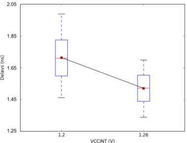
2.11 Delay ratio stability when increasing FPGA core voltage from 1.2V to 1.26V, operating temperature fixed to 25◦C. Red line shows linear regression result, green line shows degree-2 quadratic regression result. . . 26
2.12 Internal design of the ith emulation segmentEi. . . . 28
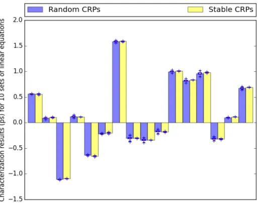
2.13 Characterization results obtained from solving 10 sets of linear equations gener-ated from random and stable CRPs. Boxes indicates 95% confidence interval. . . 32
3.1 An IPN node of sizemand lengthn. Ifm =n, the node is homogenous, otherwise it is heterogenous. . . 40
3.2 A conceptual illustration of a crossbar switch like shuffler. . . 41
3.3 Encrypting random configuration logic using existing IPN nodes. Kj is the con-figuration vector encrypted by a chain of nodes from node1 tonodej . . . 49
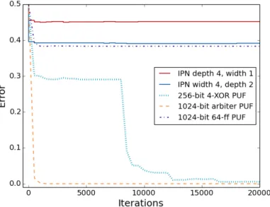
3.4 Best results in 100 logistic regression attacks using 30,000 CRP training set on five PUF-based systems. Error vs. iterations. . . 51
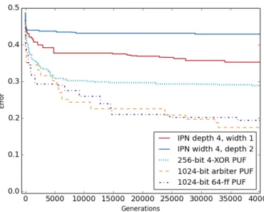
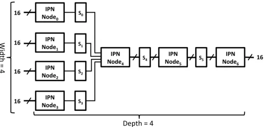
3.5 Evolution strategies attack result using 30,000 CRP training set on five PUF-based systems.. Error vs. iterations. . . 53 3.6 A 16-bit IPN network with four nodes on the first level, and has 4 levels. . . 57
4.1 An n-bit homogenous node. . . 64 4.2 An example of a simple IPN chain with shuffled connection between nodes. . . . 65 4.3 Cumulative percentage of 1,000 IPN instances that pass the NIST run test:
ran-dom search vs. ES using various numbers of maximum iterations. IPN has a chain structure of two 32-bit homogenous nodes. Scoring function threshold: 99%, near-passing threshold: 90%, backtracking threshold set at 10% of maximum number of iteration. Results collected from 1,000 sets of IPNs. . . 71 4.4 Percentage of 1,000 IPN instances that pass the NIST run test. Maximum
iter-ations are set to 10,50,100,500 and 1000. Each configuration collects 10,000-bit result. . . 72 4.5 Percentage of 1,000 IPN instances that pass the NIST run test with different node
sizes. Each configuration collects 10,000-bit result. . . 73 4.6 Percentage of 1,000 IPN instances that pass the NIST run test with different IPN
chain lengths. Each configuration collects 10,000-bit result. . . 74 4.7 Percentage of 1,000 IPN instances that pass the NIST run test with different IPN
structure. Each configuration collects 10,000-bit result. . . 75 4.8 Stability of 1,000 IPN instances of IPN chains and complex IPNs. Each IPN
node is a 32-bit homogenous node. Both the IPN chain and complex IPN has 4 levels. Complex IPNs uses a mixture of one-to-one, one-to-many and many-to-one connections. Environmental variance: 0.8∼1.0V, 0∼60◦C. . . 78
5.1 Overall architecture of our proposed CRIF. . . 84 5.2 A pair of four bit forward and backward injective function implemented using
5.3 Statistical analysis on 64-bit CRIF implementations (depth = 4). . . 91
5.4 Hamming distance distribution for avalanche effect testing measured on a 64-bit CRIF implementations (depth = 4). . . 92
6.1 The model of arbiter PUFs with an n-bit challenge. . . 101
6.2 A 4-bit leap forward LFSR example. . . 102
6.3 High level illustration of proposed design. . . 105
6.4 The two output signals from LUT6 2 are required to be in phase, but can be inverted simultaneously. . . 106
6.5 Overall implementation using LUT6 2 on FPGA. . . 106
6.6 NIST Statistical Test Suite success ratio, one thousand 10,000 bit-streams are passed to each test. The test passes for p-value ≥σ, whereσ is 0.05. The black line indicates a threshold of success ratio of 96%. All test results below this line are considered test failure. Arbiter PUF results without Von Neumann correction have success rate below 5% in most tests, thus are not shown in the figure. . . . 110
7.1 A snippet of core environment change vs. inconsistency of randomly selected APUF CRPs. The y-axis on the left is core temperature corresponding to the blue line, the y-axis on the right is the average CRP inconsistency corresponding to the red line. . . 118
7.2 VCCINT Power Module, when switch SW is open resistor RSW is inserted into the power rail. . . 120
7.3 Core environment change leads to variations in inconsistencies of ESCRP. The y-axis on the left is core temperature corresponding to the blue line, the y-axis on the right is the average CRP inconsistency corresponding to the red line. . . 123
8.1 Network structure in Omega network style. rk
i−1 indicates the k-th response (output) bit of the (i−1)-th MIPUF node,ck
i indicates thek-th challenge (input) bit of the i-th MIPUF node. . . 134 8.2 Inter-configuration and intra-configuration variation of a MIPUF with four nodes.
Each node is implemented using 64 32-bit arbiter PUFs. The interconnection between nodes is designed in a blocking fashion as shown in Figure 8.1. . . 136 8.3 Simulated global energy consumption (J) vs. total number of IoT nodes under
LIST OF TABLES
1.1 Organization of the dissertation chapters matched three major objectives. . . 5
2.1 Time required to generate 10,000 CRPs with a 64-bit PUF simulation using a HDL simulator and a 64-bit FPGA-based arbiter PUF implementation. . . 9 2.2 CRP distribution of a 64-bit arbiter PUF. 10,000 randomly selected challenges
were fed into the PUF and the bit inversion rate is calculated over 1,000 mea-surement of responses. . . 18 2.3 Delay measurement results on three FPGAs (XC6SLX45). . . 21 2.4 Linear regression results on PDL temperature stability evaluation. . . 25 2.5 PUF prediction accuracy for software simulation and PDL-based hardware
emu-lation using random CRP characterization data and stable CRP characterization data. The emulation accuracy is shown in the format of 95% confidence interval. 33 2.6 Overhead of Baseline and two-Segement PDL-based emulation of a 64-bit PUF. 33 2.7 PUF prediction accuracy for baseline emulation, two-segment emulation, and
voting. All emulation accuracy results are shown in the format of 95% confidence interval. . . 33 2.8 Baseline emulation accuracy in different environments. Characterization done
using 10 sets of stable CRPs. All emulation accuracy results are shown in the format of 95% confidence interval. . . 34 2.9 Average latency comparison in generating 10,000 CRPs using software HDL
sim-ulator, pure software simulation, and PDL-based emulation. . . 35
3.1 MLP parameters when modeling IPN. n is the depth of the network and mi is the total number of PUF segments on the i-th level. . . 53 3.2 Deep neural network attack results. . . 54 3.3 Auto-sklearn modeling results on raw CRPs. . . 55
3.4 Best prediction accuracy on different PUF architectures using machine learning algorithms out of 100 runs. Each cell contains simulated/implementation result. 56 3.5 Prediction accuracy of three attack methods. Results collected from a 100,000
test set. Logistic regression: 14 days; evolution strategies: 250,000 generations, 14 days; MLP: 18 hours. . . 58 3.6 Area overhead for implementing a IPN shown in Figure 3.6. . . 58
4.1 Success ratio of passing a NIST test for 100 IPN instances with two 32-bit ho-mogenous nodes. The maximum number of configurations allowed for each IPN is 100, each configuration collects 10,000-bit result. . . 65 4.2 Success ratio of passing NIST run test for 1,000 IPNs. Each configuration collects
10,000-bit result. . . 70 4.3 Percentage of 1,000 IPN instances that pass the NIST test suite. The IPN has
two 32-bit homogenous nodes. Each configuration collects 10,000-bit result, the maximum number of iterations is set to 1,000. . . 77
5.1 Corresponding mappings for ff orward and fbackward. . . 85 5.2 The average success ratio for the NIST statistical test suite. 100 bitstreams of
100,000 bits are passed to each test. The test passes for p-value≥ σ, where σ is 0.05. Asterisk sign (*) indicates the average case for all templates. . . 90 5.3 Single bit output prediction accuracy for different CRIF settings. Darker color
indicates stronger resilience. . . 94 5.4 Single bit input prediction accuracy for different CRIF settings. Darker color
indicates stronger resilience. . . 94 5.5 FPGA resource and power characteristics of the hardware support for
CRIF-based encryption/decryption scheme. Power measured for scheme running at 5 Mhz. . . 95
5.6 Power comparison with other power efficient AES design on FPGA. Power mea-sured for scheme running at 5 Mhz. . . 96
6.1 INIT value rules for implementing XOR gates. . . 108 6.2 FPGA resource and power characteristics: our design (four 64-bit leap forward
LFSRs loaded on eight 64-bit arbiter PUFs) vs. four standalone 64-bit leap forward LFSRs vs. 256 64-bit arbiter PUFs vs. four 64-bit leap forward LFSR and eight 64-bit arbiter PUFs that do not share hardware resources. Power per bit unit: mW/bit. . . 109
7.1 FPGA resource and power characteristics: Virtex-5 SYSMON vs. our design on Virtex-5 vs. RO-based on-chip power monitor vs. our design on Spartan-6. ADC and analog sensor area and power are not included in calculation. . . 127 7.2 anomaly detection: true positive rate (%)/false positive rate(%) using 1,000
ran-dom challenges vs. single ESC vs. 1,000 ESCs as challenge set per sample. APUFs are placed immediately besides the monitored circuit. A mixture of 1,000 abnormal temperature and VCCINT were applied to the protected circuit. . . . 127
8.1 Best single-bit prediction accuracy on different PUF architectures using logistic regression (LR), evolution strategies (ES) and deep learning (DL) attacks out of 100 runs. Each attack uses 100,000 CRPs. Total number of arbiter PUF segments used in all architectures are fixed to 1,024. . . 138 8.2 FPGA resource and power characteristics of the hardware support of our proposed
key management scheme implemented on Spartan-6 FPGA. . . 145 8.3 Performance and energy comparison of different wireless standards in IoT. . . . 146
ACKNOWLEDGMENTS
First and foremost, I would like to express my sincere gratitude to my advisor Professor Miodrag Potkonjak. It has been my highest honor to be his Ph.D. student. He has taught me not only the skills and knowledge to research in the field of computer science but also the mentality to be a hungry and forever curious researcher. I appreciate all his contribution of time, energy and ideas to make my Ph.D. study meaningful, productive and enjoyable. He stands as a role model to me as a dedicated researcher and a brave fighter against all the odds. I am forever thankful for his unconditional support in both my study and life.
Besides my advisor, I would like to thank the rest of my thesis committee: Professor Miloˇs Ercegovac, Professor Jens Palsberg, and Professor Gregory J. Pottie for their insightful comments and motivating encouragement. Their visionary suggestion and questions on my prospectus, oral examination, and final dissertation helped me gain a better understanding of my research from different perspectives.
I would also like to thank Dr. Sheng Wei and Dr. Viswanathan (Vishy) Swaminathan for providing me the opportunity as a research scientist intern at Adobe Research. Their guidance has widened my research beyond pure institutional academic research. The training I received from them made me a more efficient, productive and practical researcher.
Thank you to my colleagues and collaborators Teng Xu, Jia Guo, and Jason Zheng for discussing ideas with me, for helping me practice my talks and dissertations, for encourag-ing me to stay strong when I was strugglencourag-ing. Dr. Teng Xu spent a countless number of hours working on Recursive Inverse Functions, Hardware sharing in FPGA-based PUF im-plementation, PUF matching, and PUF-based anomaly detector projects with me. Jia Guo provided precious suggestions for performing machine learning attacks on existing PUF sys-tems. FPGA validation of many circuit designs of mine is based on Jason Zheng’s previous implementation of arbiter PUFs.
Last but not least, I could never finish my Ph.D. study without the support of my family and friends. My dearest parents are my greatest inspiration, motivation, and support. I will forever love them, and I can always feel their unconditional love under any circumstances.
And, of course, to Tiancheng Fang, who is always by my side, during my darkest times and my proudest moments of life.
VITA
2010–2014 B.S. (Computer Science), University of California, Los Angeles.
2014–2018 M.S. (Computer Science), University of California, Los Angeles.
PUBLICATIONS
T. Xu, H. Gu, M. Potkonjak, “Data Protection Using Recursive Inverse Function,” Interna-tional Conference on Field Programmable Logic and Applications (FPL), 2015.
H. Gu, T. Xu, M. Potkonjak, “An Energy-Efficient PUF Design: Computing While Racing,” ACM/IEEE International Symposium on Low Power Electronics and Design (ISLPED), pp. 142-147, 2016.
T. Xu, H. Gu, M. Potkonjak, “An Ultra-Low Energy PUF Matching Security Platform Using Programmable Delay Lines,” International Symposium on Reconfigurable Communication-centric Systems-on-Chip (ReCoSoC), 2016.
H. Gu, T. Xu, M. Potkonjak, “A low-power APUF-based environmental abnormality de-tection framework,” ACM/IEEE International Symposium on Low Power Electronics and Design (ISLPED), 2017.
H. Gu, M. Potkonjak. “Securing Interconnected PUF Network with Reconfigurability,” IEEE International Symposium on Hardware-Oriented Security and Trust (HOST), pp. 231-234, 2018.
H. Gu, V. Swaminathan. “From Thumbnails to Summaries - A Single Deep Neural Network to Rule Them All,” IEEE International Conference on Multimedia and Expo (ICME), 2018.
J. Guo, H. Gu, M. Potkonjak. “Efficient Image Sensor Subsampling for DNN-Based Image Classification,” ACM/IEEE International Symposium on Low Power Electronics and Design (ISLPED), 2018.
H. Gu, M. Potkonjak. “Efficient and Secure Group Key Management in IoT using Multistage Interconnected PUF,”. ACM/IEEE International Symposium on Low Power Electronics and Design (ISLPED), pp.8-14, 2018.
CHAPTER 1
Introduction
After decades of development, the Internet has connected countless computers in a global network system, carrying a vast range of information resources and services. Researchers and engineers in recent years have looked beyond the Internet and came to realize that our physical world is an information system by itself. Much information can be collected and utilized using sensors and actuators. The idea of proliferating physical entities in a new network creates the concept of the Internet of Things (IoT) [1].
The growth in globally connected devices is now mainly driven by IoT devices on both the consumer side and the enterprise side. By the end of the second quarter of 2018, the total number of IoT devices globally has reached 7 billion, and this number is expected to exceed 10 billion by 2020 and 22 billion by 2025 [2]. Globally, over$745 Billion were spent in 2019, and it is expected that the double-digit growth rate would be maintained for years to come [3]. IoT has been envisioned to be a revolutionary network that connects physical devices around us to perform intelligent tasks such as monitoring, communication, operation, and optimization.
Despite the ambitious master plan behind the idea of IoT as well as its rapidly growing speed, security challenges have always been a major concern in the process of further de-velopment of the technology. The IoT security problems are particularly challenging due to two seemingly irreconcilable objectives.
On the one hand, IoT requires a maximum level of security. IoT technology has enabled a broad spectrum of applications in a variety of environments. From smart appliances in homes to Industry 4.0 in factories, to intelligent clinical management in hospitals and smart city systems on city streets. In almost all IoT related applications, sensitive data of large
scale are collected, stored and transferred through IoT networks. In case of a security breach, whether it is invasive, semi-invasive or non-invasive [4], in an IoT system, adversaries could potentially gain private information such as identity, health-related records, business secrets, and even military records. The compromise of IoT devices that are associated with cyber-physical systems could be even more dangerous or even lethal in some cases. For example, security researchers Billy Rios and Jonathan Butts have shown that it is possible to hack into pacemakers and control the electrical impulses that are sent to the heart to regulate the patient’s heartbeat [5].
On the other hand, security always comes with a price; it takes energy and computational power to detect and defend against adversarial actions. Many IoT devices have highly con-strained energy and computational budget due to harsh requirements on device size, weight, and portability, leaving little resource to comply with the high-security requirement. Adopt-ing conventional security approaches in IoT could consequently lead to low performance and high maintenance cost.
In this thesis, we focus on the problem of designing and improving hardware-oriented security subsystems in IoT to perform a variety of crucial security tasks under a highly constrained environment. In defiance of the seemingly contradictory requirements, we show that it is feasible to provide the highest possible level of security under the lowest energy and computational power budget using our proposed methods.
1.1
Objectives
We believe this thesis is an adventurous exploration in three strongly correlated directions. We intend to make our contributions in meeting three objectives, respectively from the perspectives of security, energy, and applicability.
1.1.1 Security Objectives
IoT is a complex system that consists of several layers of abstraction spanning in multiple dimensions. From the physical layer of hardware sensors and controllers to the application layer that utilizes the collected IoT data for specific tasks, security vulnerabilities could be exploited anywhere, resulting in catastrophic compromise of the entire system. Majority of the current attacks on IoT systems are software attacks. Software attacks on IoT are popular because many similar security vulnerabilities are shared with other systems. In most cases, these exploited vulnerabilities are general software security problems instead of IoT specific issues. In recent years, the rise of IoT regime creates new attack surfaces as well as new security challenges at the hardware level.
Hardware security is a natural starting point for research in IoT systems as hardware is the basis of all IoT devices. Protecting IoT systems at hardware level grants system designers great flexibility to minimize energy and area cost. Security at the hardware level also provides a solution to the problem that classical cryptography could not resolve, presenting a new level of protection against emerging attack methods such as side-channel attacks [6] and physical attacks.
The security objective we claim to meet is to examine vulnerabilities in hardware security subsystems and propose robust and secure protection to these subsystems.
1.1.2 Energy Objective
A large portion of IoT devices are compact and powered by batteries due to the high require-ment of mobility. Therefore the energy budget for security subsystems is minimum if not none. Devices such as smartphones, tablets, and smartwatches require daily recharging. The high energy consumption in these devices is a major obstacle in terms of adopting advanced security modules to the system. Devices such as wireless sensors have much lower energy consumption but usually equipped with an ultra lightweight power source. These low power devices are often massively deployed over a broad area; recharging or replacing the power source is extremely costly. To reduce the cost and prolong the lifespan of each device, most
device manufacturers leave no room for security subsystems.
All devices are in great need for energy efficient security subsystems to defend against evolving attack techniques. In this thesis, we focus on both creating techniques that could boost energy efficiency in existing security primitive as well as designing novel and ultra lightweight security solutions in IoT devices and IoT applications.
1.1.3 Applicability Objective
IoT system is playing an increasingly irreplaceable role in countless numbers of applications from home automation to city infrastructure management. Newer and more creative applica-tions that could utilize IoT technology is booming at an enormous speed. Our applicability objective is to explore how we could use our efficient and robust hardware-oriented security solutions to protect and secure some of the emerging IoT-based applications.
1.2
Contributions and Organization
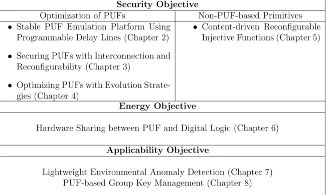
The dissertation is organized into three major parts, where each part explains our contri-bution to meet security, energy and applicability objectives. Note that even though each part focuses on its theme, the underlying logic beneath is coherent and consistent: we aim to design energy efficient hardware-oriented security subsystem for IoT and its applications. We analyze energy efficiency when introducing our proposed security techniques while we also investigate the security impact on our energy efficiency improvement techniques. The detailed organization can be viewed in Table 1.1.
The first part of the dissertation discusses low power hardware security primitives in IoT devices. We investigate security properties in hardware security primitives using two different approaches, respectively improving existing designs and creating novel architectures. We first focus on security primitives based on a promising technology - PUFs. PUF is a category of hardware functions that utilize the inevitable process variation introduced during manufacturing to create unique mappings between inputs and outputs. Recent research on
Security Objective
Optimization of PUFs Non-PUF-based Primitives
• Stable PUF Emulation Platform Using Programmable Delay Lines (Chapter 2)
• Securing PUFs with Interconnection and Reconfigurability (Chapter 3)
• Optimizing PUFs with Evolution Strate-gies (Chapter 4)
• Content-driven Reconfigurable Injective Functions (Chapter 5)
Energy Objective
Hardware Sharing between PUF and Digital Logic (Chapter 6) Applicability Objective
Lightweight Environmental Anomaly Detection (Chapter 7) PUF-based Group Key Management (Chapter 8)
Table 1.1: Organization of the dissertation chapters matched three major objectives. PUFs indicates that PUFs mainly suffers from stability issues and vulnerabilities against modeling attacks. To exploit vulnerability issues and stability weakness in some PUF designs, we first propose to utilize programmable delay lines (PDL) technology to create a platform that emulates stable arbiter PUFs with matching accuracy of 87.42% in Chapter 2. We propose the design of interconnected PUF Network (IPN) that connects multiple small PUFs in a network in Chapter 3 as an attempt to defend PUFs against modeling attacks. The interconnections in IPN can be reconfigured from time to time to completely remap the input-output pairs with low latency and low energy. We show that reconfigurable IPN is capable of preventing adversaries from collecting sufficient training data to apply modeling attacks and therefore providing robust security to protected hardware. The maximum single-bit prediction accuracy is less than 53.19% against a wide range of modeling attacks. We address the stability issues in IPN by proposing a novel mechanism that uses evolution strategies (ES) to find the best combination of PUF segments in Chapter 4, improving randomness and stability by 220.8% and 22.62% compared to unoptimized configuration. Taking a step forward, we also applying similar reconfiguration ideas to non-PUF-based security primitives.
We eventually propose Content-driven Reconfigurable Injective Function (CRIF) to conduct lightweight encryption/decryption tasks in IoT devices and communication between them in Chapter 5. We demonstrate that CRIF is an excellent alternative to cryptography-based and PUF-based competitors due to stability, efficiency, and reconfigurability, especially on IoT devices where computational power and energy are constrained. We measured CRIF achieves at least 75.04% of power savings compared to popular AES-based schemes.
The second part of the thesis is reducing energy cost in existing security primitives. We propose a novel technique called hardware “free riding” to significantly reduce area and energy overhead of analog-based PUFs. While PUFs are low power and low energy on application specific integrated circuits (ASIC), on reconfigurable hardware platforms such as field-programmable-gate-arrays (FPGA), implementation can be costly. In Chapter 6, we address this problem by introducing a technique that allows arbiter PUFs to be implemented together with any arbitrary logic on the same piece of hardware on FPGA. The evaluation shows our technique reduces 40.4% of area overhead and 7.69% of power consumption when implementing 128-bit arbiter PUFs and eight 32-bit linear-feedback shift registers (LFSR) on FPGAs.
Lastly, in the third part, we propose two applications that could greatly benefit from our proposed designs and techniques introduced in the first two parts. We first present an ultra lightweight onboard anomaly detection mechanism that has excellent potential to accurately detect suspicious voltage and temperature changes in Chapter 7. By actively monitoring sta-bility variations of onboard analog PUFs, our design could perform flexible, fine-grained chip monitoring service while reducing 63% of area and 13% of power compared to sensor-based Xilinx System Monitor. Lastly, we investigated the well-known problem of key management in IoT systems in Chapter 8. We propose to use multistage interconnected PUF (MIPUF) to assist the protection of key management system at both software and hardware level. Our experimental result indicates that our design provides physical protection when compared to Elliptic-Curve Cryptography (ECC) based solutions and reduces global energy consumption by 47.33%.
and application developers who seek to provide sufficient protection in heavily constrained environments.
CHAPTER 2
Stable PUF Emulation Platform Using Programmable
Delay Lines
2.1
Motivation
It has been widely acknowledged that physically unclonable functions (PUFs) as a type of hardware security primitive have great potentials to be used in many applications. A PUF is a device implementing a one-way function which takes advantage of process variation to guarantee the property uniqueness of each piece.
Modern research has shown that some PUF designs are not as perfect as what they seem to be. Many PUFs can be modeled using software or hardware approaches based on characterization results. This process is generally noted as PUF emulation. Though PUFs can be emulated, most state-of-the-art emulation techniques are both inefficient and inaccurate due to complication in PUF architecture and unstable nature of analog systems. Software simulations with high precision are generally slow and power-hungry, especially for complicated PUF designs. Table 2.1 shows the time required to generate 10,000 CRPs with a 64-bit arbiter PUF and a hardware description language (HDL) simulator. A software simulation of PUF needs significantly more time to produce a response compared to the use of the PUF implemented on a piece of hardware. Physically matching a PUF to a target PUF is an alternative technique. Many studies have taken place in attempting to match two PUFs using device aging technology [7], which require fine-grained control in laboratories. Since aging is a unidirectional process, both overage and underage could lead to low precision in the emulation. Thus, a highly stable operational environment is required.
Type Latency (s) HDL simulator 98.38 Hardware PUF 0.001
Table 2.1: Time required to generate 10,000 CRPs with a 64-bit PUF simulation using a HDL simulator and a 64-bit FPGA-based arbiter PUF implementation.
2.2
Technical Goal and Contributions
Our technical goal is to create a new emulation platform to resolve the above issues in standard PUF emulation techniques. The key idea is to emulate an existing PUF using hardware to achieve low latency overhead as well as resilience against operational variations. We achieve our goal by using the look-up table (LUT) based PDLs. We believe the highly stable and low latency PDL serves as an ideal building block as our PUF emulation platform. The PDL is used as a clone that shares similar delay characteristics of each segment in the standard PUFs. By accurately emulating every single segment of the target PUF, the whole emulation is capable of predicting the corresponding responses of the target PUF when provided with an arbitrary challenge.
In this chapter, we first review the related literature on PUFs and PDLs. Then we give the preliminaries of the basic PUF model we use as well as the design of PDL on FPGA. We also provide a motivational example of our PUF emulation scheme. We then propose a high precision PUF characterization mechanism that enables a PUF emulation platform. Later we demonstrate in detail our PUF emulation platform in the subsequent sections. Eventually, we provide our analysis of the reliability and accuracy of our proposed design by presenting experimental results on Spartan-6 XC6SLX45 platforms.
2.3
Related Work
2.3.1 Physical Unclonable Function (PUF)
PUF was first proposed by Pappu et al. using mesoscopic optical systems [8]. Gassend et al. developed the first silicon PUFs through the use of intrinsic process variation in deep
submicron integrated circuits [9]. A variety of other types of PUFs have since been proposed, including arbiter PUFs [9], ring oscillator PUFs [10], SRAM PUFs [11], and butterfly PUFs [12]. Xu et al. has also propose to digitalize PUFs and create digital PUFs [13]. Another popular robust PUF design is proposed by Maiti et al. with a selected PUF challenge-response set [14]. More recently, PUF designs have been focusing on improving randomness and learning-resilience, including [15] [16] [17] [18] [19]. Nozaki et al. even designs more side-channel attack resilient PUFs using statistical tests [20].
Numerous traditional protocols can be interpreted using PUFs, ranging from the tra-ditional security key communication and authentication [21] to more sophisticated public key communication [22] with the vital idea of employing the high unpredictability of PUF responses to secure the information. More recently, efforts have been made to enhance the security and randomness of PUFs. Devadas et al. have proposed to use a syndrome coding scheme to reduce the amount of information leakage caused by the traditional PUF key generation system [23]. At the system level, Zheng proposed to use PUFs as an instruction authentication tool for embedded systems [24].
PUFs have also been well studied in many novel hardware security applications. Devadas et al. proposed to use PUFs in RFID for anti-counterfeiting applications[25]. Gu et al. propose several low power applications based on PUF including computing-while-racing PUF [26] and PUF-based system anomaly detector [27]. Zhang et al. proposed a PUF-FSM binding scheme for IP-protection [28]. Xu et al. proposed an ultra-low energy PUF matching scheme using programmable delay lines [29] and device aging [30]. Gao et al. proposed to use SRAM PUF for key generations [31], Huang et al. proposed a PUF-based identity verification [32]. Gope et al. also applied PUF to RFID authentication protocols [33]. Tajik et al. designed a system monitor using PUFs [34]. Aman et al. embedded PUFs in IoT systems for mutual authentication purposes [35]. PUFs can also be used to construct Recursive Inverse Functions(RIF) that provide fast and ultra-low energy encryption and decryption for data protection [36].
2.3.2 Programmable Delay Lines (PDL)
Programmable delay lines are a series of digital delay lines with electrically programmable and trimmable delay times [37]. Taking advantage of internal structures of LUTs, Majzoobi et al. proposed to implement PDLs through creating and controlling delay biases on FPGAs [38]. PDLs are used in many different applications, including bus timing adjustment [39], programmable pulse generator at high resolution [40] and metastability characterization on FPGA [41]. Since PDLs are usually controlled at ps-level, accurate delay measurements is required. Tsai et al. proposed vernier delay line-based built-in delay measurement circuits with a small area overhead and can provide high-resolution delay measurement [42]. Ray-chowdhury et al. proposed on-chip delay estimation of segment path delays in [43]. Majzoobi et al. designed a delay characterization circuit with clock synthesis that can measure delays at picosecond resolution on FPGAs through probabilistic estimation[44].
2.3.3 PUF Attacks
Even though unclonability and unpredictability are the main characteristics of PUFs, previ-ous work has shown that PUFs are vulnerable to three types of attacks: modeling attacks, physical attacks, and side-channel attacks.
Modeling attacks are a commonly adopted approach for PUF characterization. Ruhrmair et al. proved that arbiter PUFs are weak against machine learning attacks [45]. They further analyzed the PUFs in the context of security protocols in [46]. Ganji et al. proved that ring oscillator PUFs could be completely learned using a Probably Approximately Correct (PAC) learning framework [47].
Physical attacks correspond to gate and transistor level characterization (GLC) where delay, leakage, or some other device metrics are analyzed [48]. Tajik et al. proposed a photonic emission analysis mechanism to characterize an arbiter PUF with extremely high precision [49].
Side-channel attacks have also been studied in breaking existing PUF designs. Mahmoud et al. proposed to combine modeling attacks with power side-channel attacks to better
characterize PUFs [50].
2.3.4 PUF Emulation
Many attacks on PUF designs have enabled a large number of studies in emulating a PUF device. Software simulation is one of the most popular methods to predict responses based on a given challenge. All research mentioned in Section 2.3.3 adopts software simulation to evaluate characterization accuracy. However, software simulation suffers from high latency and high energy consumption, thus not capable of providing a lightweight real-time emulation of a target PUF.
Another way of emulating a target PUF is through PUF matching (creating a physical clone of a PUF). Helfmeier et al. proposed a mechanism to produce a physical clone of an existing SRAM PUF using Focused Ion Beam circuit edit [51]. Meguerdichian et al. proposed a method to match a PUF to another PUF using device aging techniques [7]. Creating a physical clone of a PUF using the above methods requires laboratory equipment and environment, thus very expensive and difficult to achieve.
2.4
Preliminaries
2.4.1 PUF Model
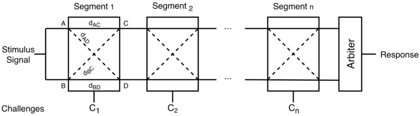
The PUFs we intend to emulate are standard arbiter PUFs. Figure 2.1 shows the schematic diagram of the PUF model. The basic structure of ann-bit PUF consists ofndelay segments. The four propagation delays in the ith segment are denoted as diAC, dBDi , diAD and diBC respectively. di
AC and diBD are considered a delay pair, and diAD and diBC are considered as another delay pair. The delays within each delay pair are designed to be nominally equal to each other. After manufacturing, however, process variation causes unpredictable delay difference within each pair. When built on an FPGA, each delay pair in each segment is directly implemented using LUTs with the same size. Two identically designed overall paths are generated by connecting delay components in each segment in a chain, and an arbiter is
appended at the end of the two paths. The two paths can be modified using the control bit of each segment. For example, in Figure 2.1, if the control bit of theith segment is 0, thendi
AC is appended to the upper segmental path anddi
BD appended to the lower segmental path. If the control bit is 1, di
BC is appended to the upper segmental path and diAD is appended to the lower segmental path. The control bit decides which two delays inside a PUF segment is appended to the PUF paths.
Arb it e r C1 C2 Cn A B C D dAC dBD d AD dBC ... ... Response Stimulus Signal Challenges
Segment 1 Segment 2 Segment n
Figure 2.1: The model of an n-bit arbiter PUF.
The vector consisting of all control bits is denoted as the PUF challenge. When an n-bit challenge (c1c2. . . cn−1cn) is provided to the PUF, two nominally identical paths are thus configured. To retrieve a response, an impulse signal is fed into the system to excite both paths simultaneously. Because of process variation, the signal traveling along one of the two paths reaches the arbiter earlier, generating a corresponding arbiter output denoted as the PUF response. For an n-bit PUF, there exist 2n challenge-response pairs.
2.4.2 PDL on FPGA
Majzoobi et al. [38] proposed a general design of PDL on FPGA platforms implemented using a single LUT-2. Figure 2.2 shows an example PDL implemented with LUT-2 with two selection bitsS0andS1. The propagation delay fromA0toOiwhenA0 = 0 is displayed in the blue line, and the same delay whenS0 = 1 is shown in the red line. The path represented in the red line seems longer than the path marked in blue according to the figure, representing the propagation delay from S0 to Oi is longer when S0 = 1. This result indicates that different input value, although completely digital, could result in a slight difference in the
Me m or y 0 0 0 1 1 1 S0 S1 Oi
Figure 2.2: The internal structure of a 2-input LUT.
analog propagation delays. We utilize the design of the slightest asymmetry in PDL design to emulate delay-based PUFs.
2.5
A Motivational Example
Segment Si PDLai PDLbi PDLci Δdi ΔdPDLi Δdi-1 ΔdPDLi-1 Matched PDL Segment 0 1Figure 2.3: An example of using PDLs to emulate a PUF.
Now we illustrate our PDL-based PUF emulation platform using a motivational example in Figure 2.3. We assume the PUF to be emulated the same structure as we explained in the Preliminaries section, where each PUF segment uses a user-provided control bit to configure the competing paths within the segment. For example, if the control bit of segment i is
zero then the delay difference between the upper and lower path ∆di = di
AC−diBD; if the control bit of segment i is one then the delay difference between the upper and lower path would instead be ∆di =di
BC −diAD. To clone segment i in the target PUF, we create three PDLs to form an emulation segment. We carefully choose the selection bits for each PDL so that the three PDLs (P DLi
a, P DLib, P DLic) are configured to obtain delays diA, diB and diC respectively. Similar to segment i in the target PUF, the ith emulation segment also takes a control bit to select which two PDL delays are appended to the path. If the control bit is 0, P DLia and P DLib are selected, producing diP DL = dia −dib ≈ ∆di = diAC −diBD as output delay difference; if the control bit is 1 P DLi
a and P DLic are selected, producing diP DL =dia−dic≈∆di =diBC−diADin output delay difference. The same emulation process is thus repeated for all segments of the target PUF. To summarize, the basic idea of emulating ann-bit PUF is to configure 3n PDLs where the delays of each PDL are configured in such a way that all delay differences produced by each PUF segment can be reproduced using PDLs.
2.6
PUF Characterization
It is well known that standard arbiter PUFs can be characterized using statistical methods [52]. In this section, we first propose a linear model for an arbiter PUF design. We claim that by solving a set of linear equations constructed by measuring PUF delay differences, we can characterize a target PUF of our choice with low overhead. The resulting model can accurately retrieve the delay differences in each PUF segment.
2.6.1 Creating Linear Equations
Assume that the characterization target is an n-bit arbiter PUF with n segments. We use the same notation as we declared in Figure 2.2. Theith PUF segment has 4 different delays. The four delays are respectively di
AC, diAD, diBC and diBD. The control bit of the segment decides which pair of delays is appended to the segmental paths shown in Equation 2.1.
Delay(Path 1), Delay(Path 2) = di AC, diBD ci = 0 di BC, diAD ci = 1 (2.1)
The two paths generate one of the two possible delay differences depending on the chal-lenge bit ci. For clarity, we denote the delay difference of the ith PUF segment to be ∆di, defined in Equation 2.2. ∆di = di AC−diBD ci = 0 di BC −diAD ci = 1 (2.2)
The value of ∆di can be either positive or negative. For example, whenc
i = 0, a positive ∆di indicates that diAC > diBD and a negative ∆di indicates that diAC < diBD.
We observe that the delay difference ∆d between the two PUF paths is merely the sum of all segmental delay differences in the PUF. Based on this observation, we can create linear equations if the delay difference between a pair of competing PUF paths is measured. Solving the equations would thus provide accurate delay difference characterization for each PUF segment.
Based on Equation 2.2, we create two variables representing the two possible delay differ-ences in each PUF segment ∆di0 =diAC−diBD and ∆di1 =diBC−diAD. For a 64-bit PUF, there are in total of 128 unknown variables. We also generate 10,000 random challenge vectors and measure the final delay differences between the two nominally identical PUF paths. The delay differences are measured using a pico-second accurate delay characterization circuit.
For N challenges, we are capable of constructing N linear equations withmunknown vari-ables. Thejth linear equation is constructed from thejth challenge vectorcj ={cj
1c j
2. . . cjm}. An example of a set of 10,000 linear equations on a 64-bit arbiter PUF is shown below.
∆d1k1 1 + ∆d 2 k1 2 +. . .+ ∆d n k1 m = ∆d measure 1 ∆d1k2 1 + ∆d 2 k2 2 +. . .+ ∆d n k2 m = ∆d measure 2 . . . ∆d1kN 1 + ∆d 2 kN 2 +. . .+ ∆d n kN m = ∆d measure N N = 10,000, m = 64 kji = 0 cji = 0 1 cji = 1
We split the 10,000 equations into 10 sets and apply a linear equation solver to find the least square solutions to solve for a close approximate of delay differences in each segment for each set. We take the average solution for each variable to be the delay difference value.
2.6.2 Improving Characterization Accuracy
PUF as a security primitive has suffered from stability issues. An unstable CRP might alter the corresponding linear equation and eventually lead to a large error rate in the delay characterization result. A stable CRP, on the other hand, is less likely to modify the linear equation, making the solutions more consistent. To improve characterization accuracy, we propose to create linear equations based on only stable CRPs.
Table 2.2 shows the CRP distribution of a 64-bit arbiter PUF. Overall, 87.94% of the responses are stable when provided with the same challenge. We define stable CRPs as CRPs that inverts its response with probability less than 10% when providing the same challenge 1,000 times. 63.5% of 10,000 challenges provides stable responses. By creating linear equations based on only stable CRPs, we believe the characterization accuracy can be improved.
Type Bit inversion rate range Frequency
Stable ≤ 10% 63.5%
Mostly Stable 10% - 30% 32.2%
Unpredictable bit inversion >30% 5.3%
Table 2.2: CRP distribution of a 64-bit arbiter PUF. 10,000 randomly selected challenges were fed into the PUF and the bit inversion rate is calculated over 1,000 measurement of responses.
2.7
PUF Emulation - PDL Evaluation
In this section, we evaluate the delay characteristics, process variation effect, and stability properties of PDL to examine the feasibility of using PDL to emulate an arbiter PUF.
2.7.1 Delay Measurement Setup
To measure and verify the delay of PDL on the FPGA we use the circuit describe by Majzoobi et al. [38]. The delay characterization circuit is shown in Figure 2.4. We assumes the clock-to-Q delay at the launch FF istclk2Q, the clock skew between the launch and sample flip-flops (FFs) is tskew, the clock pulse width is denoted as T and the time that a signal propagate through Circuit Under Test (CUT) and reach the sample FF from the moment the launch FF is clocked is denoted as tp = tCU T +tclk2Q −tskew. Noted in our experiment the CUT is essentially PDL segments connected in chains using the configurations to adjust its delay characteristics.
The pulse generator sweeps through different frequencies and calculates the approximate delay from the frequency of the clock signal that causes the timing error probability to be 50%. The measurement is valid because as we sweep the frequency of the function generated from the pulse generator T and makes it approach tp, the sample FF enters a metastable state because of the setup and hold time violations, and its output becomes nondeterministic. The probability that the metastable state resolves to a 0 or 1 is a function of how close T is totp. The metastable state resolves to a 1 with a probability of 0.5 indicate that T =tCU T. Through careful adjustment of the pulse frequency at high resolution, the circuit could achieve pico-second resolution in delay measurements.
Pulse
Generator D-FF
Circuit Under Test
(CUT) D-FF D-FF
Timing Violation
Catcher Launch FF Configurations Sample FF Capture FF
Figure 2.4: Delay characterization circuit. 2.7.2 Delay Measurement Results
Average delay of each LUT are measured and calculated under 25◦C operating temperature, 1.2V FPGA core voltage. The results are shown in Figure 2.5. Figure 2.5a shows the delay difference between any pair of configuration bits. Figure 2.5b shows the absolute value of the delay difference between any pair of configuration bits and Figure 2.5c shows the Hamming distance heatmap between each pair.
The largest difference is 13 ps, which occurs between 00000 and 11111, located at location (x,y) = (0,31) and location (31,0) in Figure 2.5a and 2.5b. The diagonal line in both figures from the lower left corner to the upper right corner is all 0s because we are comparing each configuration bit to itself.
We notice that some patterns shown in Figure 2.5b can be observed in Figure 2.5c. The upper left and the lower right corner of both heatmaps are very similar, indicating that if two configuration vectors have a large delay difference in PDL, these two vectors also have a large Hamming distance. We believe this is an accurate observation because large Hamming distance indicates that the corresponding internal signal paths share very few common routes. Consequently, it is more likely to generate a higher delay difference. However, note that sharing a few common routes does not always indicate a large delay difference. Two very distinct signal paths might produce a small delay difference. Thus, we also see many patterns in the Hamming difference heatmap are not observable in Figure 2.5b
(a) (b) (c)
(a) Delay difference between any pair of config-uration bits. Delay difference unit measured in
ps.
(a) (b) Absolute value of delay difference between any(b) (c)
pair of configuration bits. Delay difference unit measured inps.
(a) (b) (c) Hamming distance between all pairs of config-(c)
uration bits.
2.7.3 Process Variation
We have run experiments on three difference FPGA boards to test the effect of process variation. For each board, we implemented PDL on five different locations with the same design. All PDLs are provided 00000 and 11111 as configuration bits. The average delays of PDL on three boards are compared and presented in Table 2.3 indicating process variation leading to approximately 1.6% of fluctuation. However, the delay differences stay relatively stable, with variation less than 3ps. Thus, we believe it is safe to assume process variation has limited impact on PDL when implemented on similar hardware, especially when the size of PDL is relatively small.
00000 (ns) 11111 (ns) Difference (ns)
FPGA 1 0.555 0.568 0.013
FPGA 2 0.553 0.564 0.011
FPGA 3 0.546 0.556 0.010
Table 2.3: Delay measurement results on three FPGAs (XC6SLX45).
2.7.4 Stability
Ideally, any pair of configuration bits ci, cj (ci 6=cj) should produce a pair of delays with a non-zero delay difference when applied to two PDLs, and the delay difference should remain stable. However, this is not always true in reality. PDL is a timing-based scheme. Thus, it is sensitive to environmental changes. Also, the environmental impact on delays may not be equal for each path inside the PDL. Non-uniform impact on delays thus leads to instability in pairwise delay differences.
As an example, Figure 2.6 illustrates two possible outcomes of temperature variations for two PDL paths. Figure 2.6a shows a scenario where path 2 is more sensitive to temperature than path 1. At lower temperature t1, the delay on PDL path 1 dt1P ath1 is larger than the delay on PDL path 2 dt1
P ath2 (∆d1 = dt1P ath1 −dt1P ath2 > 0). However, when the temperature increases to t2, delay on path 2 increases at a faster rate, and at a point the delay on path 2 is greater than the delay on path 1 (∆d2 =dt2P ath1−dt2P ath2 <0). We intend to avoid this
Temperature Δd1 Δd2 Path 1 Path 2 t1 t2 (a) Scenario 1 Temperature Δd3 Δd4 Path 3 Path 4 t1 t2 (b) Scenario 2
Figure 2.6: Signal propagation delay of PDL vs. temperature of two PDL paths scenario because this type of instability results in sign inversion of delay differences, creating a significant error with a relatively large probability. Figure 2.6b shows an almost ideal scenario where the sign of delay differences between path 3 and path 4 (∆d3 and ∆d4) does not change as the temperature varies from t1 tot2. Also, ∆d3 ≈∆d4, which means that the delay difference value stays relatively stable as well. Stable delay difference, in turn, leads to low error rate in emulation results.
Similar to PUFs, PDL is primarily affected by temperature and voltage. To analyze how PDL behaviors can vary, we test PDL in different environmental settings. Our experimental results show that PDL is capable of producing relatively stable delay differences in normal conditions. All delay measurements are done on a chain of four PDLs using the delay characterization circuit. The PDL chain is connected serially as shown in Figure 2.7. All delays are measured from the signal-in port to the signal-out port.
PDL
1PDL
2PDL
3PDL
4 Configuration [19:15] Configuration [14:10] Configuration [9:5] Configuration [4:0] Signal-in Signal-out2.7.4.1 Temperature
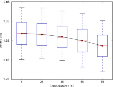
We evaluate the delays of PDL for 20,000 different configuration bits on a chain of four PDLs at five different temperatures within the allowed operating temperature range (0 ∼ 85◦C). The delays are measured using the delay characterization circuit as described in Figure 2.4. We adjust the temperature by placing the FPGA device in a temperature controlled chamber. To evaluate the delay characteristic variations as core temperature changes, we first collected delay measurements for 10,000 PDLs on FPGA. Then, we observe the stability of PDL in different temperatures through constructing 10,000 delay pairs (reference temperature vs. tested temperature) and calculate the delay ratio between each pair. Ideally, if the temperature impact on the PDL chain is uniform over all PDL paths, we should observe those delay ratios stay unchanged as we adjust the temperature. We set the delay ratios measured at 25◦C as our reference and compare all delay ratios at different temperatures with it.
Figure 2.8: Delay characteristic variation under different temperature settings.
Figure 2.8 indicates the delay characteristic changes as core temperature varies. The average delay slightly decreases by 6.89%, while the variance in delays increases by 4.25% as temperature increase from 5◦C to 85◦C.
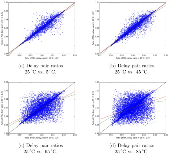
(a) Delay pair ratios 25◦C vs. 5◦C.
(b) Delay pair ratios 25◦C vs. 45◦C.
(c) Delay pair ratios 25◦C vs. 65◦C.
(d) Delay pair ratios 25◦C vs. 85◦C.
Figure 2.9: Delay ratio stability over 4 different temperature settings, VCCINT fixed at 1.2V. Red line: linear regression result. Green line: degree-2 quadratic regression result. 45◦C, 65◦C and 85◦C. Each blue point represents a specific delay ratio between two config-uration vectors, where the x coordinate is the ratio calculated in the reference temperature and the y coordinate is the ratio calculated in the test temperature. The black line in each subgraph indicates the result of a perfectly stable PDL. Linear regression (red line) and degree-2 quadratic regression (green line) were performed on the collected data. The degree-2 quadratic regressions in all four settings are very close to straight lines, indicating a linear relationship between the x-axis and the y-axis. To quantify the stability of PDL in all temperature settings, we evaluate the slope, intercept, and standard error of all linear regression results in Table 2.4.
In general, at 5◦C and 45◦C, the regression slope is very close to 1, the intercept is close to 0, and the standard error is almost negligible, meaning the impact of temperature change
Temperature Slope Intercept std err
5◦C 0.9795 0.0200 0.0027
45◦C 0.9813 0.0186 0.0030
65◦C 0.6304 0.3696 0.0075
85◦C 0.4450 0.5550 0.0093
Table 2.4: Linear regression results on PDL temperature stability evaluation.
is mostly uniform over all PDL paths so that the delay difference stays relatively stable. At higher temperatures 65◦C and 85◦C, the regression slopes are respectively 0.6304 and 0.4450, far from 1, indicating some paths are much more sensitive to the temperatures than others. This result means at very high temperature the PDL-based emulation segment result has a much higher probability of being inconsistent with the results collected at 25◦C. In our emulation platform design, we assume that the temperature varies at most 20◦C from the room temperature. Thus, it is safe to claim that PDL is stable against reasonable thermal fluctuation.
2.7.4.2 Voltage
Similar to the evaluation of thermal variations, we investigate the voltage variation impact on PDL. Our experimental platform Spartan-6 does not contain a freely tunable DC-DC converter in the power module, thus adjusting core voltage cannot be done internally. More-over, the manufacturer of our experimental platform has a fairly stringent requirement on FPGA core voltage (VCCINT = 1.2V), making it very difficult and risky to directly apply an adjustable external power source to the FPGA core. Fortunately, Spartan-6 provides an extended performance mode that applies to VCCINT = 1.26V. We first evaluate the changes in delay characteristics as we change the VCCINT in Figure 2.10. We observe that the av-erage delay slightly decreases by 11.19%, while the variance in delays decreases by 19.46% as VCCINT increase from 1.2V to 1.26V.
We also evaluate the delay ratio between 10,000 PDL delay pairs in both normal mode and extended performance mode. The result is shown in Figure 2.11.
im-Figure 2.10: Delay characteristic variation under two VCCINT settings.
Figure 2.11: Delay ratio stability when increasing FPGA core voltage from 1.2V to 1.26V, operating temperature fixed to 25◦C. Red line shows linear regression result, green line shows degree-2 quadratic regression result.
pact on each path is relatively stable and consistent. Also, both linear and degree-2 quadratic regression were performed and the results are plotted in the figure. The quadratic regression result (green line) is almost flat, indicating that a linear model is a better representation of the data. The linear regression result (red line) indicates that the delay pair ratios stay mostly stable as we increase the voltage. Linear regression has a slope of 0.9754, intercept of
0.02463, and standard error of 0.0027, very close to the ideal result (black line). Based on the results, we claim it is safe to assume that the PDL delay ratio stays relatively stable against minor changes in voltage and the impact of voltage variation is uniform over all paths.
Also, it is interesting to notice that less variance is observed on both ends of the plot. This phenomenon is also observed in temperature variation experiments. When the delay ratios are further away from 1, meaning the delay differences are larger, the PDL is less likely to behave differently when the environment changes.
2.8
PUF Emulation - Design
In this section, we discuss a PDL-based hardware emulation of a characterized PUF. We first propose a segmental emulation approach that emulates each segment in the PUF. Later we propose a method to scale the delay difference by a factor in the new emulation platform while maintaining the challenge-response relationship. Lastly, we introduce a method to find the scaling factor that maximizes emulation accuracy.
2.8.1 Perfect Segmental Emulation
The goal of perfect segmental emulation is to create an exact “clone” for each segment in the PUF so that when connecting all emulation segments together, an accurate emulation of the entire PUF is then constructed.
After the characterization process of a PUF, delay differences for each segment is re-trieved. We use three PDL to create an emulation segmentEi with three different delaysdi
A, diB anddiC to emulate theith segment of the PUF. We program the control bits of each PDL so that the three delays are capable of producing two delay differences ∆di
1 and ∆di2 that are identical to the two delay differences the ith PUF segment generates. The segmental emulation is described in Equation 2.3 and 2.4.
∆di2 =dia−dic (2.4)
If we can guarantee the validity of Equation 2.3 and 2.4, then it is safe to claim that Ei now behaves the same way the ith PUF segment behaves.
Control bit
PDL
aiPDL
biPDL
ciΔd
PDLi0
1
A
B
C
D
Figure 2.12: Internal design of the ith emulation segment Ei.
Figure 2.12 shows the internal structure of the ith emulation segment Ei. P DLia is configured to have delay ofdi
a,P DLibis configured to have delay ofdib andP DLicis configured to have delay of dic. The entire segment takes a control bit to select a pair of PDL delays to generate the desired delay difference: ∆di
1 or ∆di2.
2.8.2 Delay Difference Scaling
Perfect segmental emulation guarantees the correctness of the emulation; however, it is chal-lenging to implement. The delay difference characterization results we eventually obtained are relatively small, sometimes even less than the PDL resolution of 1 ps. Thus, it is not possible to create a perfect clone (with the same delays) of a PUF segment using PDL on an FPGA platform.
We observe that an accurate emulation can be created without a perfect segmental emu-lation. The PUF response does not depend on actual delay value, but instead the sign of the difference between competing for path delays. We can multiply the real delay difference by any positive factor α, and the sign of the difference between path delays should remain the