Volume 56, 2018, Pages 11–22
Proceedings of the 5th International OMNeT++ Community Summit
Cross-layer Stack Design Framework in OMNeT++
Doganalp Ergenc
1and Ertan Onur
21
Middle East Technical University, Turkey
2
Middle East Technical University, Turkey
Abstract
While networking applications are getting more comprehensive, the information
re-quired to perform the algorithms running upon such applications is increasing. Even
though the modular design of network stacks provides an important abstraction between layers, it is now necessary to use all layer-specific information in cooperation. Therefore, cross-layer applications are designed for years. However, implementing and testing them in network simulators are still complex. In this study, we implemented a cross-layer design onto TCP/IP stack and gave a guide to design this architecture in OMNeT++. We also investigated the design in an example use case that is a clustering algorithm for ad-hoc networks.
1
Introduction
Network applications have become more complex in design. They require various and precise information to optimize and improve existing designs and develop new applications that outgun the current state-of-the-art. Cross-layer architecture enables the designers to benefit from a variety of layer-specific information in a layered stack design. That is, it exploits the layered-structure of an architecture to promote inter-layer communication and procure flexibility to use layer-specific information through the whole (or between some specific) layers. In this sense, it is an architectural optimization technique that increases the control over the information flow. Cross-layer optimization is considered for a number of problems such as effective routing, clustering, energy conservation and caching [1][2][3].
• We review three well-known cross-layer architectures, and some example OMNeT++ implementations for cross-layer designs (Section2).
• We give a detailed guideline of a cross-layer stack architecture in OMNeT++ (Section
3). This is a complete roadmap with sample codes to create cross-layer TCP/IP stack. We also publish a ready-to-use implementation for a generalized cross-layer design1. This implementation is prepared for OMNeT++ v5.1.1 usinginet v3.6.0 framework.
• We present the full picture of OMNeT++ modules to illustrate an example cross-layer design in our use case (Section4).
2
Related Work
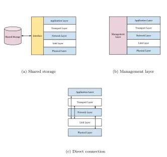
Designs with different requirements determine the structural aspects of the cross-layer architec-ture. For instance, frequency, quantity, and direction of information sharing between layers are some of those requirements. Generally, three main cross-layer architectures are proposed in the literature; (a) shared storage, (b) management layer and (c) direct connection [4]. In a cross-layer design, (a) a shared storage is accessed by the cross-layers to extract and update commonly-used information. It could be considered as a micro-level database with layer interfaces as shown in Figure 1a. Especially when all layers need to share information, defining a single shared storage for common usage is much more effective than the one-to-one connection between each layer [1]. (b) Figure1bshows the management layer that is (vertically) placed as a proxy layer between multiple layers and has a role to manage different parameters that belong to other layers. It is able to make asynchronous requests to other layers to obtain or update parameters. Similarly, it can be accessed by any other layer for application-specific purposes [2]. (c) For the architecture where fewer layers need to work in cooperation, connecting them directly could be the least-cost option. Direct connection in cross-layer schema means that related layers are connected without any intermediary mechanism as it exists in the shared storage and the management layer architectures [3][5]. Figure 1illustrates all those cross-layer architectures.
There are also some studies that promote the implementation of such approaches in OM-NeT++. Massin et al. [6] propose a cross-layer design for content transmission. They use a cross-layer architecture with a management layer called XLI. However, they focus on the physical layer and link layer designs instead of a cross-layer architecture to optimize the qual-ity of service (QoS) for multimedia applications. Even though implementation-specific details of radio access and resource allocation are well-explained in the study, it is not clear enough to be referenced for designing a cross-layer stack. Mohaghegh et al. [7] focus on QoS in his implementation to decrease delay in packet processing. They analyze the average processing time of the packets with different priority and compare plain and cross-layer architectures. It is stated that the experiments are conducted in OMNeT++ creating a sensor network but the implementation details are not presented in the paper. In [8], a cross-layer protocol for wake-up radios, DoRa, is presented. An abstract structure of OMNeT++ design is given in the paper, and also performance results for the new wake-up radio mechanism are presented. However, the cross-layer design in this paper offers a limited collaboration between the physical layer and link layer. Since such limited cross-layer design satisfies the requirements of the protocol, there is no discussion for the implementation details of a generic cross-layer architecture. Lastly, [9] presents an XML-based structure to pass cross-layer information through control info, which is a built-in method in OMNeT++. It does not provide a complete cross-layer design but an
Application Layer
Transport Layer
Network Layer
Link Layer
Physical Layer Interface
Shared Storage
(a) Shared storage
Application Layer
Transport Layer
Network Layer
Link Layer
Physical Layer Management
Layer
(b) Management layer
Application Layer
Transport Layer
Network Layer
Link Layer
Physical Layer
(c) Direct connection
Figure 1: Three main cross-layer architectures: shared storage, management layer and direct connection.
insight to improve current packet-passing mechanism. None of those studies presents a guide-line to design a generic cross-layer architecture but discusses the results of their proposals in specific subjects. Therefore, this study addresses the absence of the details for such a generic framework.
3
Implementation of Cross-layer Framework
of limited inter-layer connection. However, its extensibility is limited when all layers require inter-communication. Therefore, we implemented the management layer to design a general-purpose framework onto the 5-layer stack where each layer can potentially share information with others.
Application Layer
Transport Layer
Network Layer
Link Layer
Physical Layer
Inter-layer Orchestrator
Reckoner Management Layer
Routing Module
(a) The management layer is placed vertically to other lay-ers. While inter-layer orchestrator manages the communica-tion between any two layers, reckoner implements the specific logic of the related protocol or design.
Management Layer
cSimple
initialize()
handleMessage(cMessage*)
finish()
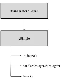
(b) OMNeT++ extension for the manage-ment layer
Figure 2: Abstract representations of the management layer and the overall stack.
The management layer in a cross-layer design has multiple roles:
• Collecting fresh information/parameters from other layers,
• Evaluating the information obtained from other layers simultaneously to make decisions,
• Forwarding any information from one layer to another to orchestrate collaboration.
Figure 2a shows the architecture having such roles. The management layer is vertically connected to the stack to be in communication with all layers. It basically consists of two submodules, the inter-layer orchestrator and the reckoner. The inter-layer orchestrator forwards the packets for communication between layers. On the other hand, the reckoner uses related packets coming from other layers to perform protocol-specific logic. In this sense, it is the brain of a cross-layer stack with the management layer.
There are three main steps to implement this architecture in OMNeT++:
1. Definition of the management layer includes the implementation of substeps for
creating a new module that is able to communicate with other layers and make protocol-specific operations.
2. Extension of other layersshows how to extend related layers to work in collaboration,
3. Creation of a new nodeis the final step to compound the management layer and other extended layers in a single structure to constitute a complete cross-layer stack.
In the rest of this section, the overall design will be explained considering those steps.
3.1
Definition of the Management Layer
The fundamentals for creating the layer are given here. For the sake of simplicity, the cross-layer structure, which is formed by following the steps, does not contain the reckoner. Because the outcome of the steps is a generalized cross-layer framework and does not embrace a protocol-specific logic. One can add the reckoner submodule after implementing the backbone structure that is exemplified through this section. Moreover, an example use of the reckoner is presented in Section4.
Definition of the management layer consists of two steps. First, we create a NED file that includes required gates to communicate with other layers and also specific parameters for the management layer. Then, we define and implement the gates in C++ classes and handle the inter-layer communication.
3.1.1 Layer-specific parameters and gates in NED files
Gates are basically full- or half-duplex channels to send interlayer packets. In this design, we used half-duplex gates that are specifically defined as input or output gate. Parameters, on the other hand, include different types of module-specific variables and signals that are detailedly explained in the OMNeT++ manual. Figure3 shows the example gate definition for a 5-layer stack. There exist an input and output gate for each layer in order. Those gates are needed to be defined in C++ to be able to process incoming packets, and also to send packets via output gates to other layers.
Figure 3: NED for the management layer.
Through all study, the motivation for this kind of implementation-level preferences is keeping sample codes as simple as possible.
3.1.2 Packet-handling scheme for inter-layer communication in C++
To program the main logic of the layer, we need to define C++ classes in parallel with NED file. OMNeT++ has extendable modules having the functions to (a) make initial definitions, (b) handle incoming packets and (c) handle module termination. That is, those functions are ready for extension/reimplementation with built-in event handlers. cSimpleModule class gives require interfaces to extend and implement our custom management layer module. Besides, basic send/receive functions are also implemented in that module. Figure2bshows the simple extension of related modules and functions for general use.
Definition of the new module and porting gates in NED to C++ objects are very trivial. Figure 4a and 4b show the definition and implementation of those steps in the initialization
(cSimpleModule::initialize()) function of the base module. They are actually not obligatory; it is also possible to access to gates through their names as strings. It is syntactically possible, albeit not a convenient and clear use in practice. Both uses of them are exemplified in Figure
6bbut porting them to C++ variables in use is recommended.
(a) Header file and definitions (b) Initilization phase in C++
Figure 4: The Initialization for gates in C++.
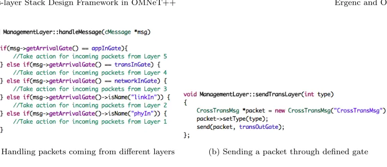
After the gates are defined, handling incoming packets and sending outgoing packets via related gates are trivial. Basically,message handling function of the base module is triggered whenever a packet arrives in a module. Besides, it is possible to take action with respect to the input gate that a packet has come. Figure5ashows the backbone of packet handling function that is controlled by simple conditionals. Note that, what to perform in such conditionals completely depends on the protocol-design. Similarly, Figure 5b shows a brief use of send
(cSimpleModule::send(cMessage*, cGate*)) function of the base module.
layer-(a) Handling packets coming from different layers (b) Sending a packet through defined gate
Figure 5: Controlling the inter-layer communication.
related information represented by C++ objects. Apart from this method, OMNeT++ has two main built-in features to perform such communication, (a) signaling and (b) control info. (a) Signaling is basically a publish-subscribe method. A signal is actually a value that can be defined as some primitive data types such as integer and float, and also object pointers. When a module emits (or publishes) a signal, all other modules that are subscribed to that signal can access its value. It is the main method to collect statistics in OMNeT++. For instance, when each module signals the number of packets it has processed, the host of those modules obtains the statistics for the total number of packets processed by subscribing to the signals. For such purpose, signaling is quite practical: defining signals in NED file for source modules and registering to them in receiver modules are enough. (b) Control info, on the other hand, is a ready-to-use object and can be attached to other message objects. For instance, one can attach a control info to a MAC frame in the link layer to be detached and processed in the application layer.
Those packet-passing mechanisms have their own advantages and disadvantages. While signaling is perfect to collect statistics using primitive data types, sharing more complex data types via signals and processing them during network lifetime are more challenging. One needs to implement related listener classes extendingcListener and overwriting its methods to handle custom signals. Even if control info requires almost no extra implementation overhead (except the definition of a custom object to pass related parameters), is not a convenient way if it is required to gather a collective information from multiple modules to process them simultaneously. Our proposed scheme, on the other hand, requires extra gate definitions. For the stack design, our scheme is like a natural extension of current TCP/IP stack implementation whose inter-layer packet-passing mechanism is also performed through gates. Therefore, we believe that it is easy to adopt and implement.
3.2
Extension of Other Layers
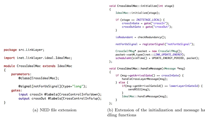
IdealMac in OMNeT++ to create aCrossIdealMac. Modification/extension in NED file, defi-nition and initialization of the gates, and the extension of the message handling and finishing functions are shown in the figure as well.
(a) NED file extension (b) Extension of the initialization and message han-dling functions
Figure 6: Extension of layers modifying NED and C++ file.
Note that, the example code pieces in Figure6a are just simplified versions; they are illus-trative for the fundamentals of the design taken from the use-case presented in Section4. There are many other implementation-specific details for defining modules, handling namespaces etc. that are out of the scope of this study.
3.3
Creation of a New Node
After the definition of the management layer and the extension of other layers, all those layers need to be connected to each other under a single node definition. This, at least for this example, does not require any reimplementation in C++ but a structure in a NED file. OMNeT++ already has a variety of node definitions which have different capabilities. For example, a generic host for wireless communication, more specific ad-hoc host as an extension of generic wireless host and routing hosts implementing different routing algorithms exist in theinet framework. Therefore, instead of defining a node from scratch, modifying one of them depending on one’s projects requirements would be easier and faster.
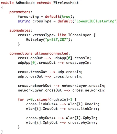
Figure 7: NED file for the definition of a new node extending wireless host.
Another important point is the selection of extended modules for an active use in our node definition. That is, the node needs to be configured to include our extended modules. It is, for example, handled in the base node definitions (NodeBase and StandartHost) which are extended by the OMNeT++ module, WirelessHost. This is quite trivial and parametric but still a step that requires attention.
4
A Use Case: A Cross-layer Clustering Algorithm for
Ad-hoc Networks
There is a variety of use cases for cross-layer designs in wireless networks [4][10]. Security, QoS, and mobility are the major issues to handle using cross-layer architectures. In this section, our own cross-layer design to implement a clustering algorithm for mobile ad-hoc networks is presented in a use case study. Note that, rather than internal details and analytical discussion of the study, we only investigate how we design and use cross-layer architecture for clustering. That study has been recently published [11], and all empirical results are collected using the framework that we presented in this paper.
design becomes crucial to be able to collect and evaluate such information. In this use case, we present the general structure of Density-aware Probabilistic Clustering Algorithm (PCA), that uses individual node degrees as an indicator of the probability of being cluster head.
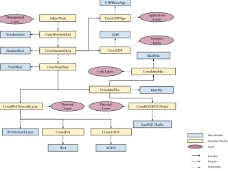
AdhocNode CrossWirelessHost CrossStandartHost CrossNodeBase CrossIPv4NetworkLayer CrossIPv4 CrossIdealNic CrossIdealMac CrossIEEE80211Radio Ieee80211Radio IdealMac IPv4 Physical Layer IPv4NetworkLayer Management Layer Transport Layer Link Layer Network Layer CrossUDP UDP WirelessHost StandartHost NodeBase CrossAODV AODV IdealNic Base Module Extended Module Layer Extends Includes Implements CrossUDPApp UDPBasicApp Application Layer
Figure 8: The overall OMNeT++ architecture for PCA that shows all module extensions.
Figure8shows the overall OMNeT++ architecture for cross-layer design in PCA. Note that, even though physical layer is not directly involved in cross-layer structure, it is also extended to form a complete framework. Depending on the design requirements, one does not have to cover all layers vertically. For PCA, only four layers (i.e., 3+1 including management layer) are necessary. (1) For the link layer,CrossIdealMac, is designed as an extension ofIdealMac. In this module, received MAC packets are forwarded to the management layer where the reck-oner counts the number of neighbors in 1-hop to compute the probability of being cluster head for the receiver node during the bootstrapping phase. In this phase, nodes explore their local neighborhood to understand if they are eligible to be a cluster head. In this method, a higher number of neighbors increase the probability for being cluster head. At the end of bootstrap-ping phase, some of the nodes claim themselves as cluster head depending on the probability calculated by reckoner in the management layer. Then, they need to announce such claim and the maintenance phase starts. For the announcement, (2) we implementedCrossUDPApp
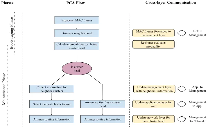
the identifier of the cluster head. Eventually, every node resides in a cluster as a cluster head or ordinary node. After the reckoner made this decision, (3) the management layer informs the network layer about the cluster head. The network layer, CrossIPv4NetworkLayer, is imple-mented as an extension ofIPv4NetworkLayer. Besides,CrossAODV is our routing module and it is integrated into the network layer. Once the network layer becomes aware of the identifier of the cluster head node, the data packets for end-to-end communication are started to forward to that node by the network layer. In this sense,CrossIPv4NetworkLayer is configured to com-municate with related cluster head so that it can orchestrate the communication in a cluster. During network lifetime, the management layer constantly informsCrossIPv4NetworkLayer in case of changing cluster. Figure9 shows the flow chart for PCA including bootstrapping and maintenance phases and inter-layer communication.
Broadcast MAC frames
Discover neighborhood MAC frames forwarded to management layer
Is cluster head
Select the best cluster to join Announce itself as a cluster head
Update application layer for role Calculate probability for being
cluster head
Reckoner evaluates probability
Collect information for neighbor clusters
Arrange routing information
Arrange routing information Update network layer for new cluster head
Cross-layer Communication
Bootstraping Phase
Maintenance Phase
PCA Flow Phases
Update management layer with neighbors’ information
Link to Management
App. to Management
Management to App.
Management to Network
Figure 9: Flow chart for PCA shows cross-layer functionalities. On the left side, the phases of PCA are associated with related flow-tasks. On the right side, cross-layer communication steps are associated with those tasks as well. Besides, the direction of cross-layer communication is noted for each step.
The performance of the algorithm evaluated using this model and extensive results are presented in [11]. This is a very concrete example of a cross-layer design in OMNeT++ to test a design in different scenarios such as different channel models, mobility models, and network density. The whole model is designed using the guidance in the scope of this study, and most of the code pieces shown here are the simplified versions of the original model.
5
Conclusion and Future Work
projects.
There are indeed different methods to develop a cross-layer architecture and they are also required to be examined and compared to find the one (a) with a shallow learning curve, (b) with less development cost and (c) is adaptable to a variety of projects. Besides, the implementation-specific issues like packet-passing mechanisms are needed to be evaluated em-pirically to understand performance overhead. Such optimization issues are left as the future work after this study.
6
Acknowledgement
This work is partially supported by ASELSAN Inc.
References
[1] R. Glitho, C. Fu, and F. Khendek. Cross-Layer Design for Optimizing the Performance of
Clusters-Based Application Layer Schemes in Mobile Ad Hoc Networks. InProc. of the 4th IEEE Consumer
Communications and Networking Conference, pages 239–243, Jan 2007.
[2] M. K. Denko, J. Tian, T. K. R. Nkwe, and M. S. Obaidat. Cluster-Based Cross-Layer Design
for Cooperative Caching in Mobile Ad Hoc Networks. IEEE Systems Journal, 3(4):499–508, Dec
2009.
[3] R. Mehta and D. K. Lobiyal. Energy efficient cross-layer design in MANETs. InProc. of the 4th
International Conference on Signal Processing and Integrated Networks (SPIN), pages 448–453, Feb 2017.
[4] V. Srivastava and M. Motani. Cross-layer design: a survey and the road ahead.IEEE
Communi-cations Magazine, 43(12):112–119, 2005.
[5] J. Peng, H. Niu, W. Huang, X. Yin, and Y. Jiang. Cross layer design and optimization for
multi-hop ad hoc networks. InProc. of the IEEE 2nd Advanced Information Technology, Electronic and
Automation Control Conference (IAEAC), pages 1678–1682, March 2017.
[6] R. Massin, C. Lamy-Bergot, C. J. Le Martret, and R. Fracchia. OMNeT++-Based Cross-Layer
Simulator for Content Transmission over Wireless Ad Hoc Networks.EURASIP Journal on
Wire-less Communications and Networking, 2010(1):502549, Jan 2010.
[7] M. Mohaghegh, C. Manford, and A. Sarrafzadeh. Cross-layer optimisation for quality of
ser-vice support in wireless sensor networks. InProc. of the IEEE 3rd International Conference on
Communication Software and Networks, pages 528–533, May 2011.
[8] Jean Lebreton and Nour Murad. Implementation of a Wake-up Radio Cross-Layer Protocol in
OMNeT++, MiXiM. CoRR, abs/1509.03553, 2015.
[9] Laura Marie Feeney. Managing cross layer information in OMNeT++ network simulations. [10] B. Fu, Y. Xiao, H. J. Deng, and H. Zeng. A Survey of Cross-Layer Designs in Wireless Networks.
IEEE Communications Surveys Tutorials, 16(1):110–126, First 2014.
[11] Doganalp Ergenc, Levent Eksert, and Ertan Onur. Density-aware Probabilistic Clustering in Ad
hoc Networks. InProc. of the IEEE International Black Sea Conference on Communications and
Networking (BlackSeaCom), Batumi, Georgia, jun 2018.
[12] O. Boyinbode, H. Le, A. Mbogho, M. Takizawa, and R. Poliah. A Survey on Clustering Algorithms
for Wireless Sensor Networks. InProc. of the 13th International Conference on Network-Based
Information Systems, pages 358–364, Sept 2010.
[13] Craig Cooper, Daniel Franklin, Montserrat Ros, Farzad Safaei, and Mehran Abolhasan. A
com-parative survey of VANET clustering techniques. IEEE Communications Surveys & Tutorials,