125 Available online at www.ijiere.com
International Journal of Innovative and Emerging
Research in Engineering
e-ISSN: 2394 - 3343 p-ISSN: 2394 - 5494
Analysis of the behaviour of Cable stayed bridge with
different types of cables arrangement
Shivanshi
a, Pinaki
baAssistant Professor, Department of Structural engineering, CPU, Kota, India bB.Tech. Student, Gurukul Institute of Engineering and Technology, Kota, India
ABSTRACT:
The Cable Stayed Bridge consists of cables. There are many types of cable arrangements among that we chose fan type, semi fan type and harp type arrangements. The bridge is designed and analyzed for these cables arrangement by STAAD Pro software. The most efficient arrangement is proposed after analysis among three. The comparison is made for Shear force, bending moment, displacements for the cases. The results are summarized and discussed. Then comparisons are made for the three cases. The conclusion is made in respect to the efficiency of one of the arrangements. This can be useful in the modifying the drawbacks of others. This work would give directions to make other arrangements more efficient.
Keywords: cable stayed bridge, fan arrangement, semi fan arrangement ,harp arrangement, STAAD pro, finite element method
I. INTRODUCTION
Cable stayed bridges have good stability, optimum use of structural materials, aesthetic, relatively low design and maintenance costs, and efficient structural characteristics. Therefore, this type of bridges are becoming more and more popular and are usually preferred for long span crossings compared to suspension bridges. A cable-stayed bridge consists of one or more towers with cables supporting the bridge deck. In terms of cable arrangements, the most common types of cable stayed bridges are fan, harp, and semi fan bridges. Because of their large size and nonlinear structural behavior, the analysis of these types of bridges is more complicated than conventional bridges. In these bridges, the cables are the main source of nonlinearity. An optimum design of a cable-stayed bridge with minimum cost while achieving strength and serviceability requirements is a challenging task. In this thesis, cable stayed bridge is analyzed by changing he cables arrangement each time, to obtain the results for bending moment, forces, deflection. The three cable’s arrangement taken is fan, semi fan and harp arrangement. Comparison between the three types, in terms of forces, bending moment and deflection, is carried out in this thesis. The bridge is analyzed by the commercial finite element based software STAAD Pro.
II. LITERATURE REVIEW
A typical cable stayed bridge is a deck with one or two pylons erected above the piers in the middle of the span. The cables are attached diagonally to the girder to provide additional supports. The pylons form the primary load-bearing structure in these types of bridges. Large amounts of compression forces are transferred from the deck to the cables to the pylons and into the foundation. The design of the bridge is conducted such that the static horizontal forces resulting from dead load are almost balanced to minimize the height of the pylon. Cable stayed-bridges have a low center of gravity, which makes them efficient in resisting earthquakes. Cable stayed bridges provide outstanding architectural appearance due to their small diameter cables and unique overhead structure [1]
The arrangements of cables showing fan, semi fan and harp are shown in following figures. III.ANALYSIS
(A) OBJECTIVE
126
“Figure 1. A simple illustration of cable-stayed bridge”,“Figure 2. Arrangements of cables-Fan ,Semi fan and Harp”.[2]
(B) PROBLEM STATEMENT
1. Cable stayed bridge with Fan arrangement of cables 2. Cable stayed bridge with Semi-Fan arrangement of cables 3. Cable stayed bridge with Harp arrangement of cables (C) DESCRIPTION OF BRIDGE
Analysis is made for cable stayed bridge. The total span of the bridge is 200 m. The total width of the deck of the bridge is 10 m. The diagram of bridge is as shown in Figure.3.In construction; firstly edge beams are erected and then followed by deck slab with crossbeams. The total height of bridge is 65 m. The pylon used here is H shaped. Bridges with Fan arrangement, Semi fan arrangement and harp arrangement are as shown in Figure 4, Figure 5 and Figure 6. The live load, earthquake load, vehicle load are not considered. The thesis is limited to the three cables arrangement only, other are not considered. The properties limited only to the shear force, bending moment and deflections. Other evaluations are not considered.
(a)
127 “Figure 4. Cable stayed bridge with Fan arrangement of cables”
“Figure 5. Cable stayed bridge with Semi- Fan arrangement of cables”
128 Comparison
Table 2: Max and Min shear forces and bending moment for Semi fan arrangement
Beam Node Fx kN Fy kN Fz kN Mx kNm My kNm Mz kNm
Max Fx 143 8 49380.65 425.997 7.56 -143.768 282.812 -3885.79 Max Fy 52 4 -631.521 2822.607 2.667 1073.929 -37.731 1173.516 Max Fz 7 4 46077.04 423.043 149.473 -154.229 -988.488 6662.639 Max Mx 52 4 -631.521 2822.607 2.667 1073.929 -37.731 1173.516 Max My 142 29 36065.86 -394.557 -149.473 179.289 1464.834 -6412.14 Max Mz 7 4 46077.04 423.043 149.473 -154.229 -988.488 6662.639
Min Fx 589 105 -3500.78 277.159 0 0 0 0
Min Fy 343 28 -385.299 -2670.75 89.573 -994.782 110.621 1632.245 Min Fz 142 29 36065.86 -394.557 -149.473 179.289 1464.834 -6412.14 Min Mx 110 5 -631.521 2822.607 -2.667 -1073.93 37.731 1173.516 Min My 7 4 46077.04 423.043 149.473 -154.229 -988.488 6662.639
Min Mz 386 171 -233.801 1105.384 0 0 0 -7947.83
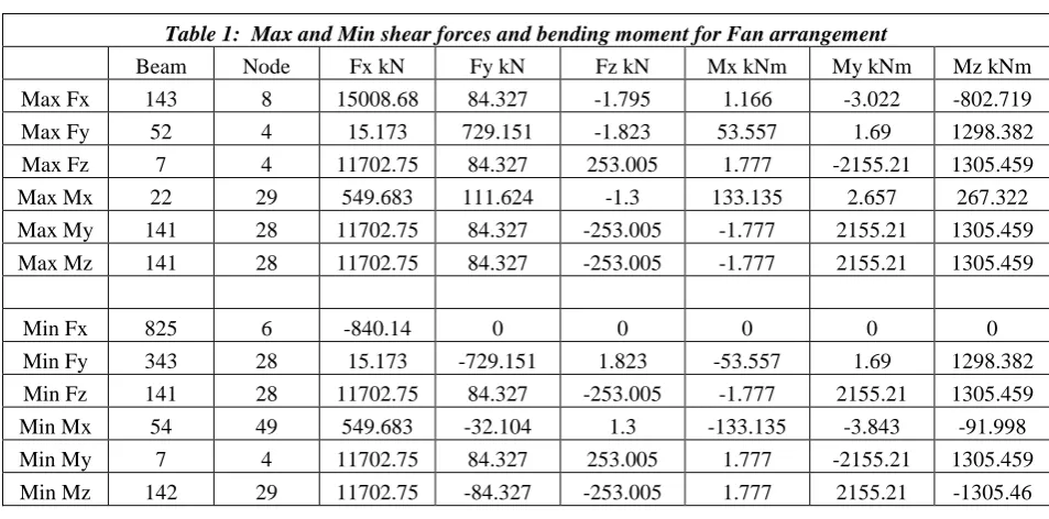
Table 1: Max and Min shear forces and bending moment for Fan arrangement
Beam Node Fx kN Fy kN Fz kN Mx kNm My kNm Mz kNm
Max Fx 143 8 15008.68 84.327 -1.795 1.166 -3.022 -802.719
Max Fy 52 4 15.173 729.151 -1.823 53.557 1.69 1298.382
Max Fz 7 4 11702.75 84.327 253.005 1.777 -2155.21 1305.459
Max Mx 22 29 549.683 111.624 -1.3 133.135 2.657 267.322
Max My 141 28 11702.75 84.327 -253.005 -1.777 2155.21 1305.459 Max Mz 141 28 11702.75 84.327 -253.005 -1.777 2155.21 1305.459
Min Fx 825 6 -840.14 0 0 0 0 0
Min Fy 343 28 15.173 -729.151 1.823 -53.557 1.69 1298.382
Min Fz 141 28 11702.75 84.327 -253.005 -1.777 2155.21 1305.459
Min Mx 54 49 549.683 -32.104 1.3 -133.135 -3.843 -91.998
Min My 7 4 11702.75 84.327 253.005 1.777 -2155.21 1305.459
Min Mz 142 29 11702.75 -84.327 -253.005 1.777 2155.21 -1305.46
Table 3: Max and Min shear forces and bending moment for Harp arrangement
Horizontal Vertical Horizontal Resultant
Node X mm Y mm Z mm mm
Max X 105 36.72 -10.868 16.581 41.73
Min X 104 -36.72 -10.868 16.581 41.73
Max Y 67 0 31.52 -0.015 31.52
Min Y 14 3.866 -80.353 0.017 80.446
Max Z 104 -36.72 -10.868 16.581 41.73
Min Z 6 -36.72 -10.868 -16.581 41.73
Max rX 67 0 31.52 -0.015 31.52
Min rX 66 0 31.52 0.015 31.52
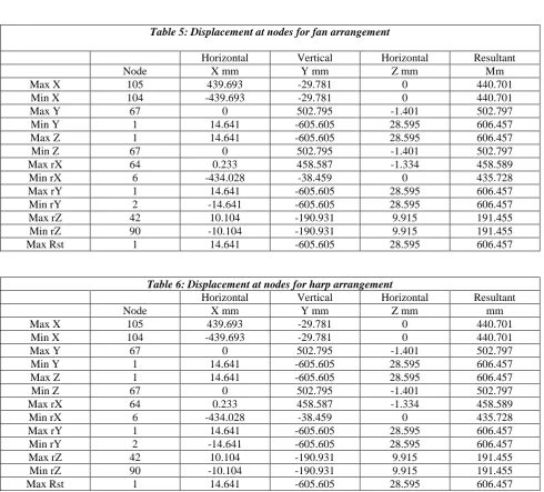
129 Table 5: Displacement at nodes for fan arrangement
Horizontal Vertical Horizontal Resultant
Node X mm Y mm Z mm Mm
Max X 105 439.693 -29.781 0 440.701
Min X 104 -439.693 -29.781 0 440.701
Max Y 67 0 502.795 -1.401 502.797
Min Y 1 14.641 -605.605 28.595 606.457
Max Z 1 14.641 -605.605 28.595 606.457
Min Z 67 0 502.795 -1.401 502.797
Max rX 64 0.233 458.587 -1.334 458.589
Min rX 6 -434.028 -38.459 0 435.728
Max rY 1 14.641 -605.605 28.595 606.457
Min rY 2 -14.641 -605.605 28.595 606.457
Max rZ 42 10.104 -190.931 9.915 191.455
Min rZ 90 -10.104 -190.931 9.915 191.455
Max Rst 1 14.641 -605.605 28.595 606.457
Table 6: Displacement at nodes for harp arrangement
Horizontal Vertical Horizontal Resultant
Node X mm Y mm Z mm mm
Max X 105 439.693 -29.781 0 440.701
Min X 104 -439.693 -29.781 0 440.701
Max Y 67 0 502.795 -1.401 502.797
Min Y 1 14.641 -605.605 28.595 606.457
Max Z 1 14.641 -605.605 28.595 606.457
Min Z 67 0 502.795 -1.401 502.797
Max rX 64 0.233 458.587 -1.334 458.589
Min rX 6 -434.028 -38.459 0 435.728
Max rY 1 14.641 -605.605 28.595 606.457
Min rY 2 -14.641 -605.605 28.595 606.457
Max rZ 42 10.104 -190.931 9.915 191.455
Min rZ 90 -10.104 -190.931 9.915 191.455
Max Rst 1 14.641 -605.605 28.595 606.457
Min rY 2 -4.021 -64.666 0.062 64.791
Max rZ 153 2.211 -24.952 0.006 25.05
Min rZ 189 -2.211 -24.952 0.006 25.05
Max Rst 14 3.866 -80.353 0.017 80.446
Table4: Displacement at nodes for fan arrangement
Beam Node Fx kN Fy kN Fz kN Mx kNm My kNm Mz kNm
Max Fx 143 8 15008.68 80.431 5.01 1.353 23.245 -789.921
Max Fy 52 4 -54.892 593.809 -2.334 13.343 2.194 1126.318
Max Fz 7 4 11702.75 80.431 177.918 2.061 -1482.51 1220.862
Max Mx 4 5 925.493 40.246 -0.325 177.428 1.393 117.767
Max My 141 28 11702.75 80.431 -177.918 -2.061 1482.505 1220.862 Max Mz 141 28 11702.75 80.431 -177.918 -2.061 1482.505 1220.862
Min Fx 868 32 -832.894 0 0 0 0 0
Min Fy 343 28 -54.892 -593.809 2.334 -13.343 2.194 1126.318
Min Fz 141 28 11702.75 80.431 -177.918 -2.061 1482.505 1220.862
Min Mx 23 29 925.493 40.246 0.325 -177.428 -1.393 117.767
Min My 7 4 11702.75 80.431 177.918 2.061 -1482.51 1220.862
130 “Figure 7: At Node 105, Max displacement for Fan, Semi-Fan and Harp”,
“Figure 8 . At Node 105, Min displacement for Fan, Semi-Fan and Harp”.
“Figure 9. At Node 67, Min displacement for Fan, Semi-Fan and Harp”
“Figure. 10 At Node 1, Min displacement in for Fan, Semi-Fan and Harp”.
-200 0 200 400 600 800 1000
X mm Y mm Z mm mm
Horizontal Vertical Horizontal Resultant
Harp Semifan Fan -1500 -1000 -500 0 500 1000 1500
X mm Y mm Z mm mm
Horizontal Vertical Horizontal Resultant
Harp Semifan Fan -200 0 200 400 600 800 1000 1200
X mm Y mm Z mm mm
Horizontal Vertical Horizontal Resultant
Harp Semifan Fan -1500 -1000 -500 0 500 1000 1500
X mm Y mm Z mm mm
Horizontal Vertical Horizontal Resultant
131 “Figure 11. At Node 67, Min displacement for Fan, Semi-Fan and Harp”.
(A) Beam Shear Forces and Bending moment
“Figure 12.At Node 11, Shear force for Fan, Semi-Fan and Harp”.
Figure 13. At Node 8, Bending moment for Fan, Semi-Fan and Harp
-200 0 200 400 600 800 1000 1200
X mm Y mm Z mm mm
Horizontal Vertical Horizontal Resultant
Harp Semifan Fan
-20000 0 20000 40000 60000 80000 100000
Fx kN Fy kN Fz kN
Harp Semifan Fan
-6000 -4000 -2000 0 2000
Mx kNm My kNm Mz kNm Harp
132 “Figure 14. At Node 4, Shear force for Fan, Semi-Fan and Harp”.
“Figure 15. At Node 4, Shear force for Fan, Semi-Fan and Harp”.
“Figure 16. At Node 4, Bending moment for Fan, Semi-Fan and Harp”.
IV.RESULT AND CONCLUSION
In this section, the results for the efficient design of the three arrangements of cable-stayed brides including semi-fan, fan, and harp arrangements are presented. The purpose of this to study the effect of different cables configurations on bridge component like pylon, deck, cables, and total cost. The graphical summarized results are as shown:
-1000 0 1000 2000 3000 4000 5000
Fx kN Fy kN Fz kN
Harp Semifan Fan
0 20000 40000 60000 80000
Fx kN Fy kN Fz kN
Harp Semifan Fan
-10000 -5000 0 5000 10000
Mx kNm My kNm Mz kNm
133 “Figure 17. Graph for total Deflection for fan, semi fan and harp type arrangements”.
“Figure 18. Graph for total Shear force for fan, semi fan and harp type arrangements”.
“Figure 19. Graph for total Bending Moment for fan, semi fan and harp type arrangements”.
The specific results that can be drawn from this analysis are numerated as follows: 1. The shear force is more in harp than semi fan and least in fan arrangement 2. The bending moment is more in harp than semi fan and least in fan arrangement
0 500 1000 1500
Fan semi fan Harp
Deflection
Deflection
0 50000 100000 150000
Fan Semi-fan Harp
Shear Force( in KN)
Shear Force( in KN)
0 5000 10000 15000 20000
Fan Semifan Harp
Bending Moment(in kNm)
134 3. The deflection is more in harp than semi fan and least in fan arrangement
CONCLUSION
In this study, an implementation of three types of cables arrangement for the design of the cable-stayed bridges have been introduced considering fan ,semi fan and harp arrangements. The shear force, bending moment, deflection for three types of cable-stayed bridges are compared with each other and the result of comparisons are reported. First, bridge is developed for fan, semi fan and harp arrangements of cable stayed bridges. Then effect of these arrangements on the stability and efficiency of bridge components are investigated for fan, semi fan and harp arrangements are compared. At the end, the most efficient out of all these three arrangements is proposed. The results indicated that the fan arrangement is more efficient then two other arrangement.
ACKNOWLEDGMENT
First of all I feel great pleasure in acknowledging my deepest gratitude to my revered guide and mentor, Mr Nitin Nagar, Assistant Professor, Structural Engineering Department, Career Point University, Kota, under whose firm guidance, motivation and vigilant supervision for successful completion of my research work. He infused in to me the enthusiasm to work on this topic. His tolerance nature accepted my shortcomings and he synergized his impeccable knowledge with my curiosity to learn in to this fruitful result.
I would also like to thank to entire members of IJIERE for providing me the best platform for presenting the research work.
REFERENCES
[1] Olfat S.Zadeh (2012),Comparison Between Three types of Cable Stayed Bridge using Structural Optimization [2] Aye Nyein Thu, Dr San Yu Khaing “Structural Behaviors of Long-span Cable-Stayed Bridge with due to Wind
speed”, ,Internatinal Journals of Engineering &Technology,oct 2014
[3] Mostafa Salehi , Ahmad Shooshastri,Vahab Esmaili,Alireza Naghavi Riabi. “Non-Linear Analysis of Cable Structures under general loading”, Finite elements in Analysis and Design,2013
[4] “On the Structural Analysis and Design of Cable stayed bridge and suspension Bridges”,Fabio,marco,Pier Giorgio,International Conference on Bridge maintenance ,safety and management, oct 2004