STATIC ANALYSIS OF RETAINING WALL WITH & WITHOUT SHELF BY USING
F.E.M SIMULATION
Mr. Rohan R. Watve*1 Prof. Dr. D.N.Shinde2 1*Civil Department, PVPIT Budhgaon, India.
2Civil Department, PVPIT Budhgaon, India.
KEYWORDS
:
Retaining Wall, Stadd proV8i, Self-weight, Eatrh Pressure, Stem, Heel, Toe.ABSTRACT
The most distinctive feature of the finite element method that separates it from other conventional methods is the division of a given domain into a set of simple sub domains, called finite elements. Any geometric shape that allows computation of the solution or its approximation, or provides necessary relations among the values of solution at selected points, called nodes, of the sub domain, qualifies as finite elements. Other features of the method include seeking continuous, often polynomial, approximations of the solutions over each elements in terms of nodal values, and the assembly of element equations by imposing the inter element continuity of the solution and balance of inter element forces.
INTRODUCTION
The most Distinctive feature of the finite element method that separates it from other conventional methods is the division of a given domain into a set of simple sub domains, called finite elements.
Steps involved in the finite element analysis of a typical problem are shown below.
i. Discretization (or representation) of the given domain into a collection of element formulation of the equation is completed.
a. Construct the finite element mesh of the prescribed elements. b. Number the nodes and elements.
c. Generate the geometric properties (e.g. coordinates and cross sectional areas) needed for the problem.
ii. Derivation of the element equations for all typical elements in the mesh.
a. Construct the variation of unknown formulation of the given equation over the typical element. b. Assume the typical dependent variable u is the form of
u
ni1u
i
i .... (4.1 And substitute it into step ii-a to obtain element equations in the form.c. Derive or select, if already available in literature, element interpolation function ψi and compute element matrices. Assembly of the element equation to obtain equation of whole problem.
d. Identify the inter element continuity conditions among the primary variables (relationship between local degrees of freedom and global degrees of freedom – connectivity of the elements) by relating element nodes to global nodes.
e. Identify the “Equilibrium” conditions among the secondary variables (relationship between the local source or force components and globally specified source components).
f. Assemble the element equations.
iii. Imposition of the boundary conditions of the problem
a. Identify the specified global primary degrees of freedom. Identify the specified global secondary degrees of freedom.
iv. Solution of the assembled equations. i) Post processing of the results
a. Compute the gradient of the solution or other desired quantities from the Primary degrees of freedom computed in step iii-a.
b. Represent the result in tabular and/or Graphical form.
1) Retaining wall Without Shelve (Fig no. 1a) 2) Retaining Wall With Shelve (Fig no.1b)
MATERIALS AND METHODS
Introduction to STAAD-Pro
For finite element modeling, STAAD-Pro V8i software is used. STAAD-Pro V8i is the most popular structural engineering software product for 2D as well as 3D model generation, analysis and multi-material design. It has an intuitive, user-friendly GUI, visualization tools, powerful analysis and design facilities and seamless integration to several other modeling and design software products. The software is fully compatible with all Windows operating systems. For static or dynamic analysis of bridges, containment structures, embedded structures (tunnels and culverts), pipe racks, steel, concrete, aluminum or timber buildings, transmission towers, stadiums or any other simple or complex structure, STAAD-Pro has been the choice of design professionals around the world for their specific analysis needs.
Model of retaining wall without and with shelf in STAAD-Pro:
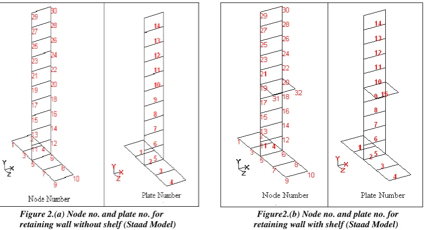
STAAD-Pro is used to perform finite element analyses of retaining wall without and with shelf. The model of the cantilever reinforced concrete retaining wall without and with shelf is generated in Space structure (which is a three-dimensional framed structure with loads applied in any plane) and using four nodded plate element. The model of the retaining wall without shelf includes 30 nodes and 14 plates and the wall with shelf includes 32 nodes and 15 plates. Node no. 1 to 6 on toe slab, node no. 5 to 10 on heel slab, node no. 5, 6, 11 to 30 on stem on node no. 31 & 32 on shelf. Node no. 5& 6 is common for toe, heel and stem. Plate no. 1 & 2 on toe slab, plate no. 3 & 4 on heel slab, plate no. 5 to 14 on stem on plate no. 15 on shelf. Figure no. 4.1 and 4.2 show the Node no. and plate no. for retaining wall without and with shelf.
Figure 2.(a) Node no. and plate no. for Figure2.(b) Node no. and plate no. for retaining wall without shelf (Staad Model) retaining wall with shelf (Staad Model)
heel and stem acts as cantilever member so fix support provide at their intersection joint. Figure no. 4.3 shows the fix support position for retaining wall without and with shelf.
Figure 3 Fix support position for retaining wall (Staad Model fig.)
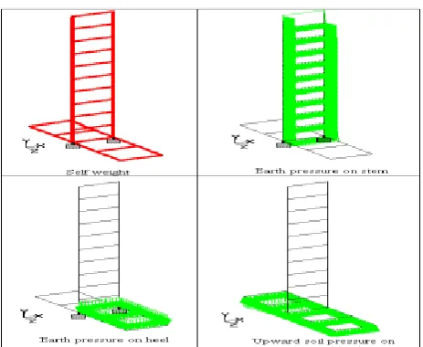
From load page option Load cases are made for different type loads such as self-weight of wall, earth pressure on stem and heel etc. These load cases are discussed below in details.
Loading on Retaining wall without shelf:
Load case 1: Self-weight of retaining wall. Load case 2: Earth pressure on stem. Load case 3: Earth pressure on heel. Load case 4: Upward soil pressure on toe. Load case 5: Upward soil pressure on heel.
Figure 4: Loading on Retaining wall without shelf (Stadd Model)
Loading on Retaining wall with shelf at mid span:
Load case 1: Self-weight of retaining wall. Load case 2: Earth pressure on stem above shelf. Load case 3: Earth pressure on stem below shelf Load case 4: Earth pressure on shelf.
Load case 5: Earth pressure on heel below shelf. Load case 6: Earth pressure on heel.
Figure5: Loading on Retaining wall with shelf
RESULTS AND DISCUSSION
Modeling of the retaining wall and analysis in STAAD-Pro
A four node plate element model is prepared for cantilever reinforced concrete retaining wall without and with shelf.
Modeling of Retaining wall without shelf
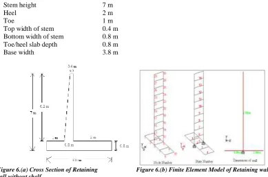
Figures shows the cross section and finite element model of retaining wall without shelf respectively. The model is prepared for the following geometry of wall.
Stem height 7 m
Heel 2 m
Toe 1 m
Top width of stem 0.4 m Bottom width of stem 0.8 m Toe/heel slab depth 0.8 m
Base width 3.8 m
Figure 6.(a) Cross Section of Retaining Figure 6.(b) Finite Element Model of Retaining wall wall without shelf
Analysis result: Support reaction:
Table 1: Support reaction for retaining wall without shelf
Load Case Fx kN Fy kN Fz kN
Load case 1: Self-weight of retaining wall. 0 -169 0
Load case 2: Earth pressure on stem. 0 0 -163.345
Load case 4: Upward soil pressure on toe. 0 274.674 0
Load case 5: Upward soil pressure on heel 0 142.322 0
Support moments:
Table 2: Support Moment for retaining wall without shelf
Load Case Mx kNm Mz kNm Load case 1: Self-weight of retaining wall. - -238.92 Load case 2: Earth pressure on stem. 381.138 0 Load case 3: Earth pressure on heel. - -372 Load case 4: Upward soil pressure on toe. - 412.011 Load case 5: Upward soil pressure on heel - 213.483
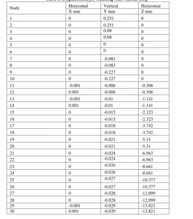
Displacement:
(Node 1-4 on toe, Node 7-10 on heel, Node 11- 30 on stem, Node 5&6 common for toe, heel and stem)
Table 3: Displacement for retaining wall without shelf
Node Horizontal Vertical Horizontal X mm Y mm Z mm
1 0 0.251 0
2 0 0.251 0
3 0 0.08 0
4 0 0.08 0
5 0 0 0
6 0 0 0
7 0 -0.083 0
8 0 -0.083 0
9 0 -0.227 0
10 0 -0.227 0
Figure 7. Displacement of retaining wall without shelf
Modeling of Retaining wall with shelf at mid span of stem
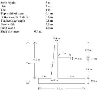
The modeling is done on Retaining wall with shelf. The shelf is provided at the mid height of the stem. Figure 5.8 and figure 5.9 shows the cross section and finite element model of retaining wall with shelf respectively. The model is prepared for following geometry of wall.
Stem height 7 m
Heel 2 m
Toe 1 m
Top width of stem 0.4 m Bottom width of stem 0.8 m Toe/heel slab depth 0.8 m
Base width 3.8 m
Shelf width 1.0 m
Shelf thickness 0.4 m
Figure 8. Cross Section of Retaining wall with shelf at mid span
Analysis result: Support reaction:
Table 4: Support reaction for retaining wall with shelf at mid span
Load case 1: Self-weight of retaining wall.
0 -179 0 Load case 2: Earth pressure on stem above shelf. 0 0 -36.167 Load case 3: Earth pressure on stem below shelf 0 0 -36.167 Load case 4: Earth pressure on shelf. 0 -62 0 Load case 5: Earth pressure on heel below shelf. 0 -62 0 Load case 6: Earth pressure on heel 0 -124 0 Load case 7: Upward soil pressure on toe.
0 210.025 0 Load case 8: Upward soil pressure on heel. 0 209.046 0
Support moment:
Table 5: Support moment for retaining wall with shelf at mid span
Load Case Mx kN Mz kN Load case 1: Self-weight of retaining wall. 0 -268.5 Load case 2: Earth pressure on stem above shelf. -168.781 0 Load case 3: Earth pressure on stem below shelf -42.195 0 Load case 4: Earth pressure on shelf. 0 -93 Load case 5: Earth pressure on heel below shelf. 0 -93 Load case 6: Earth pressure on heel 0 -186 Load case 7: Upward soil pressure on toe. 0 315.038 Load case 8: Upward soil pressure on heel. 0 313.568
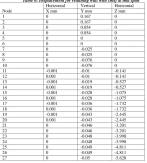
Displacement:
(Node 1-4 on toe, Node 7-10 on heel, Node 11- 30 on stem, Node 31&32 on shelf, Node 5&6 common for toe, heel and stem)
Table 6: Displacement for retaining wall with shelf at mid span
Node
Horizontal Vertical Horizontal X mm Y mm Z mm
1 0 0.167 0
2 0 0.167 0
3 0 0.054 0
4 0 0.054 0
5 0 0 0
6 0 0 0
7 0 -0.025 0
8 0 -0.025 0
9 0 -0.076 0
28 0 -0.05 -5.628 29 -0.001 -0.051 -6.447 30 0.001 -0.051 -6.447 31 -0.001 0.879 -2.446 32 0.001 0.879 -2.446
Figure 9: Displacement of retaining wall with shelf at mid span
Same modeling and analysis done for varying the position of shelf also width of shelf the following table Give clear idea about varying the position
Combination of location and width
Table No7): Combination of location factor and shelf factor
Combination Shelf
width Shelf location from top
Combination 1 0.25 m 0.2 h 0.4 h 0.5 h 0.6 h 0.8 h
Combination 2 0.50 m 0.2 h 0.4 h 0.5 h 0.6 h 0.8 h
Combination 3 0.75 m 0.2 h 0.4 h 0.5 h 0.6 h 0.8 h
Combination 4 1.0 m 0.2 h 0.4 h 0.5 h 0.6 h 0.8 h
The Following Observations are done after all Work is completed
Support reaction
Self-weight of retaining wall:
Table 8: Self-weight of retaining wall
Shelf width Shelf position (Load in kN)
0.2 h 0.4 h 0.5 h 0.6 h 0.8 h 0.25 m 129.688 129.688 129.688 129.688 129.688 0.50 m 130.625 130.625 130.625 130.625 130.625 0.75 m 131.563 131.563 131.563 131.563 131.563 1.0 m 132.5 132.5 132.5 132.5 132.5
Support Moment:
Moment due to self-weight
Table 9: Moment due to self-weight
Shelf width
Shelf position (Moment in kN.m)
0.2 h 0.4 h 0.5 h 0.6 h 0.8 h 0.25 m 194.53 194.53 194.53 194.53 194.53 0.50 m 195.94 195.94 195.94 195.94 195.94 0.75 m 197.344 197.344 197.344 197.344 197.344 1.0 m 198.75 198.75 198.75 198.75 198.75
Table (9) gives the values of moment due to self-weight of retaining wall. The values of moment are increases with increasing the width of shelf and it same for particular location.
DISPLACEMENT
Displacement of top node
Table10: Displacement of top node
Shelf width Shelf position (Displacement in mm)
0.2 h 0.4 h 0.5 h 0.6 h 0.8 h 0.25 m 9.699 10.076 11.838 13.494 15.902 0.50 m 9.390 9.806 11.278 12.925 15.480 0.75 m 8.876 8.959 10.345 11.977 14.776 1.0 m 8.156 7.773 9.038 10.651 13.792
Graph 1. Displacement of top node for shelf location
Displacement of middle node
Table11: Displacement of middle node
Shelf width Shelf position (Displacement in mm)
0.2 h 0.4 h 0.5 h 0.6 h 0.8 h 0.25 m 3.757 3.723 4.341 4.999 6.045 0.50 m 3.677 3.643 4.155 4.786 5.857 0.75 m 3.544 3.392 3.845 4.431 5.545 1.0 m 3.057 3.040 3.410 3.934 5.108
0 0.2 0.4 0.6 0.8
6 7 8 9 1011121314151617
S
h
el
f p
o
si
ti
o
n
Displacement (mm)
Displacement of top node
0.25 m
0.50 m
0.75 m
Graph 2. Displacement of top node for shelf location
CONCLUSION
The retaining wall with relief shelf is proved to be advantageous over the cantilever and counterfort retaining wall. The finite element analysis of 2-D model of retaining wall by using STAAD-Pro is performed in this work. The software STAAD-Pro can be suitably applied for the structural analysis of such type of wall. The study of deflections, bending moment, support reactions, etc. on various components of retaining wall can be performed by this software.
Following are the concluding remarks.
1. The best location for the single shelf is observed to be in between 0.4 h to 0.5 h for the maximum reduction in earth pressure, less bending moments and less deflection.
2. The deflection of the stem is reduced by about 41.50% by providing shelf at 0.5 h than the deflect ion given without shelf.
3. The deflection of the stem depends mainly on the shelf location and it increases for the shelf located from 0.2 h to 0.8 h.
4. The deflection reduces by increasing the width of the shelf but the variation is less.
5. The pattern of occurrence of bending moment on toe for all the shelves (0.25 m, 0.50 m, 0.75 m, 1.0 m) is same in X & Y direction.
6. Displacement of shelf reduces as the width of shelf increases at a particular location.
7. Self-weight of retaining wall with shelf increases due to which stability force increases and retaining wall become more stable.
REFERENCES
1. Suliman B.A.Mohamed,Kuo-Hsing Yang.(2014):Finite element analyses of two-tier geosynthetic reinforced soil wall comparison involving centrifuge test and limit equilibrium results.
2. Padhye R. D. (2010),Ph.D. thesis on “Analysis and Design of Retaining Walls with Pressure Relief Shelves”.
3. Syed Mohd. Ahmad and P. K. Basudhar, (2008)“Behaviour of reinforced soil retaining wall under static loading using finite element method”The 12th International Conference
4. Kevin Abraham (2007), “Three dimensional behavior of retaining wall systems,” A Dissertation for the degree of Doctor of Philosophy. The Department of Civil and Environmental Engineering. M.S., MississippiStateUniversity.
5. P.E.Pinto and C.G.Lai (2006) “Numerical Modelling & Seismic Behavior of Earth Retaining Walls”. 6. Padhye R. D. &Ullagaddi P. B., (2005),“Retaining Walls with Pressure Relief Shelf – A Review Study”,
All India Seminars on, “Advances in Geotechnical Engineering”. National Institute of Technology, Rourkela. pp 62
7. Varghese P.C. (2005), “Foundation Engineering”, Prentice Hall of India Pvt. Ltd. New Delhi.
8. Seung –Hoon Lee, Buhm soo Chang (2004) Two-Parameter Beam-column model and back analyses for flexible Earth retaining walls.
9. J.R.Blake, J.P.Renaud ,M.G.Anderson,(2003)Prediction of rainfall-induced transient Water pressure behind a retaining wall using a high resolution finite element model.
0 0.2 0.4 0.6 0.8
2 3 4 5 6 7
S
h
el
f p
o
si
ti
o
n
Displacement (mm)
Displacement of middle node
Shelf width 0.25 m
Shelf width 0.50 m
10. Ray Chaudhuri P. et al (1973), Paper No. 295. “Design of Retaining Walls with relieving shelves” IRCJournal, Volume 35, part 2, pp 289 - 325.
11. G. Wayne Clough and James M. Duncan, (1971) “Finite Element Analyses of Retaining Wall Behavior”Vol. 97, No. 12, pp.1657-1673.