_____________________________________________________________________________________________________ 5(1): 1-14, 2019; Article no.JERR.47628
Chemical Process Absorption Column Design for
CO
2
Sequestration
Ikenna C. Nwokedi
1*and Philomena K. Igbokwe
11
Department of Chemical Engineering, Nnamdi Azikiwe University, P.M.B. 5025, Awka, Anambra State, Nigeria.
Authors’ contributions
This work was carried out in collaboration between both authors. Both authors read and approved the final manuscript.
Article Information
DOI: 10.9734/JERR/2019/v5i116915 Editor(s): (1) Dr. Ravi Kant, Professor, Department of Physics, Bhai Gurdas Degree College, Maharaja Ranjit Singh Sate Technical University, Bathinda (Punjab), India. (2) Dr. Leandro A. Pasa, Professor, Campus Medianeira da Universidade Tecnologica Federal do Parana, Brazil.
Reviewers: (1) Antipas T. S. Massawe, University of Dar Es Salaam, Tanzania. (2) Julian Cruz-Olivares, Autonomous University of State of Mexico, Mexico. Complete Peer review History: http://www.sdiarticle3.com/review-history/47628
Received 23 February 2019 Accepted 1 May 2019 Published 10 May 2019
ABSTRACT
The design of a prototype chemical process absorption column was carried out to facilitate the sequestration of CO2 from flue gas emanating from an exhaust point of a power generating set. Factors such as ambient temperature and atmospheric pressure where factored into consideration before the fabrication of the absorption column. The rate of the absorbing liquid is 0.1056kg/min and contains 5% mole/mole carbon (iv) oxide. Also the energy and material balance of the entire sequestration process was verified as well as the equipment design for the process was carried out.
Keywords: Material balance; energy balance; CO2 sequestration; ammonia; equipment design; absorption column; knockout drum; absorber; evaporative gas cooler; solution cooler; solution heat exchanger; flash drum; stripper; and reboiler.
1. INTRODUCTION
The scientific community agrees that anthropogenic CO2 emission, mainly generating
by fossil-fuel power plants, is among the main contributors to global warming [1]. Although the transition of the existing infrastructure from carbon-based sources to cleaner alternatives
would be ideal in this regard, such a change requires considerable modifications to the current energy framework, and many of the proposed technologies are not yet sufficiently developed to facilitate large-scale industrial implementation [2]. Thus, carbon capture and sequestration (CCS) technology that efficiently capture CO2 from existing emission sources will play a vital role until more significant modifications to the energy infrastructure can be realized. Plant design is a technical term that embraces all engineering aspects involved in the development of either a new, modified, or expanded industrial plant [3]. It involves the economic evaluation of new processes, design of industrial pieces of equipment for a new plant or the development a plant layout for the co-ordination of the overall operation [4]. Present strategies for the mitigation of the atmospheric carbon (IV) oxide build-up are relied on the energy use efficiency, and the reduction of fossil fuels consumption for increased use of renewable energy sources or nuclear power plants. Thus, the inevitable way of keeping the global CO2 load in the atmosphere and hydrosphere below unbearable levels is the complementing of emission reduction [5] efforts by the capture CO2 before it emits from point sources, or from its carrying air stream emitting from the point of sources, and to store it permanently outside the atmosphere.
2. MATERIALS AND METHODS
2.1 Methodology
Due to the nature of the equipment made of glassware and in order to control the experiment, standard conditions of ambient temperature and atmospheric pressure were adopted for the process, and also for the flow rate of the solution into the absorption column. Three independent variables were used: the concentration of solvent ranging from 2-10 mol/dm3, contact time of 20-100 seconds and volume of solvent from 40-200 ml.
For the carbon sequestration to be achieved, 10 mol/dm3 concentration of aqueous ammonia was prepared and poured into a flask containing ammonia solution which supplied the solution to the absorber, the aqueous ammonia was evenly distributed across the inner surface of the column while in contact with the plates. The petrol generating set was turned on while the gas analyzer detected the components and quantity of gases before it was charged into the heat exchanger. The heat exchanger helped to attain
the desired temperature of 40oC before the flue gas was charged into the absorption column from the entry point near the base of the absorption column. The flue gas in the column contacted with the aqueous ammonia in a counter current form for a period of 60 seconds after which the tap at the exit point close to the top of the absorption column was opened and gas analyzer used to determine the amount of CO2 leaving the column.
2.2 Chemical Absorption-Amine
Absorption/Stripping Technology
A typical chemical absorption process consists of an absorber and a stripper in which absorbent is thermally regenerated [6]. Chemical absorption process was the adopted method for this work with ammonia used as the absorbent. Ammonia was chosen as the most suitable solvent and absorbent for this work because of its large absorption capacity, small heat of reaction, fast kinetics, high CO2 selectivity, it is cheap and does not degrade and ammonia is not affected by O2 and SO2. In a chemical absorption process, the flue gas containing CO2 enters a packed bed absorber from the bottom and contacts counter-currently with a CO2-lean absorbent, after absorption, the CO2-rich absorbent flows into a stripper for thermal regeneration. In the aftermath regeneration, the CO2-lean absorbent is pumped back to the absorber for cyclic use. The pure CO2 released from the stripper is compressed for subsequent transportation and storage [7]. The advantage of a chemical absorption technology is that it is the most matured technology for CO2 capture and it has been commercialized for many decades. Another advantage of this technology is that it is suitable for retrofitting of the existing power plants.
2.3 Materials
Equation for the Reaction: [8,9]
i) CO2 Absorption
2CO2 (g) + 2NH3(aq) + H
ii) Ammonia Regeneration
NH2COONH+4(aq) + H
About 98% recovery of CO2 occurs and the recovery liquid is a 20% w/w NH3
Assumptions:
1) The rate of the absorbing liquid is 0.1056kg/min and contains 5% mole/mole carbon (iv) oxide.
2) The spent air effluent analysis, 0.000347ft3/s at 300C, 1atm with % composition on dry basis of carbon (IV) oxide (3.5%), nitrogen (79%) and oxygen (17.5%). The exit air is saturated with water vapour at the absorbing liquid inlet temperature of 400C.
3) Recovery of 85% CO2. 4) Reaction equation
Process Details:
Basis: 1 minute operation
Fig. 1. Experimental set-up and sketch diagram for absorption using the prototype semi
Nwokedi and Igbokwe; JERR, 5(1): 1-14, 2019; Article no.
(aq) + H2O → NH2COONH+4(aq) + H2CO3
(aq) + H2O → H2CO3 + 2NH3
occurs and the
The rate of the absorbing liquid is 0.1056kg/min and contains 5% mole/mole
The spent air effluent analysis, C, 1atm with % of carbon (IV) oxide (3.5%), nitrogen (79%) and oxygen (17.5%). The exit air is saturated with water vapour at the absorbing liquid inlet
Feed Stream
Stream 2: Spent air effluent (dry basis) CO2 = 3.5%
Nitrogen = 79% Oxygen = 17.5%
Total volume of spent air effluent =
0.000347Ft3/s
3. RESULTS AND DISCUSSION
The capturing of CO2 from spent air effluent was achieved through the absorption of CO ammonia solution to form ammonia carbamate which was later regenerated to recover the ammonia and CO2. The raw gas (air effluent from a generating set) was cooled to about 40 (reaction temp.) and separated to remove any condensed water from the raw gas. Dry air effluent was charged to the absorption column. In
up and sketch diagram for absorption using the prototype semi column
; Article no.JERR.47628
Stream 2: Spent air effluent (dry basis)
of spent air effluent =
RESULTS AND DISCUSSION
from spent air effluent was achieved through the absorption of CO2 with ammonia solution to form ammonia carbamate which was later regenerated to recover the . The raw gas (air effluent from a generating set) was cooled to about 400C (reaction temp.) and separated to remove any condensed water from the raw gas. Dry air effluent was charged to the absorption column. In
the absorption section the air was charged counter currently with ammonia solution from the top and the CO2 was absorbed to form ammonium carbamate [10]. The off air from absorption section was water washed in the wash section to remove any entrained liquid. The scrubbed gas recovered as overhead was sent to the knock-out drum to recover any entrained ammonia solution from the absorption column. The rich-amine solution from the bottom of the absorber was passed to energy recovery system and a solution heat exchanger where it was pre-heated to about 1500C (regeneration temperature). The spent ammonia solution exchange heat with incoming regenerated ammonia solution from bottom of the regenerator [11]. Pre-heated spent ammonia solution was separated to remove any gas associated with the spent ammonia solution. Regeneration of ammonia solution was carried out in the regenerator by the application of heat supplied by steam generated in the reboiler at the base of the regenerator. The top product of regenerator contains mainly CO2 and steam which was cooled in the cooler to condense them. The steam was separated and returned to the reboiler [12].
The bottom product of regenerator containing regenerated ammonia solution was passed through solution heat exchanger where it exchanges heat with spent ammonia solution from the absorber. It was further cooled to bring its temperature to about 400C (absorption temperature).
3.1 Material Balance Results
3.1.1 Material balance summary tables
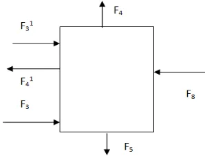
3.1.1.1 Absorber
Fig. 2. Material balance diagram for absorber
Table 1. Absorber input streams
Comp Mol.
Wt
F3 F8 F31
Mole kmol/ hr
Mass kg/hr Mole kmol/ hr
Mass kg/hr
Mole kmol/ hr
Mass kg/hr
CO2 44 0.0000118 0.0000364 0.0000118 0.0005192 -
-O2 32 0.000526 0.000133 - - - -
N2 28 0.000133 0.000526 - - - -
NH3 17 - - 0.00118 0.02006 - -
H2O 18 - - 0.08496 0.08496 - 0.001015
H2CO3 61 - - - -
Carbamate 62 - - - -
Total 0.0006954 0.01055 0.001015
Table 2. Absorber output streams
Comp Mol.
Wt
F41 F4 F5
Mole kmol/ hr
Mass kg/hr
Mole kmol/ hr
Mass kg/hr Mole kmol/ hr Mass
kg/hr
CO2 44 - - 0.02006 0.000484 0.0000118 0.0005192
O2 32 - - 0.08406 0.000526 - -
N2 28 - - 0.000043 0.000133 - -
NH3 17 - - - 0.0005713 0.0000118 0.02006
H2O 18 - 0.001015 - 0.000286 0.000000701 0.08406
H2CO3 61 - - - - 0.000000701 0.000043
Carbamate 62 - - - - 0.000000701 0.000053
Nwokedi and Igbokwe; JERR, 5(1): 1-14, 2019; Article no.JERR.47628
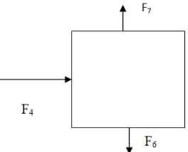
3.1.1.2 Knock-Out Drum 1
Fig. 3. Material balance diagram for knock out drum 1
Table 3. Knock-out drum 1 calculation details
Comp Input (F4) Output (F6) Output (F7)
Mol. /wt Mole Kmol/h
Mass kg/hr Mole kmol/hr
Mass Kg/hr
Mole Kmol/hr
Mass Kg/hr
CO2 44 0.000484 0.000484 - - 0.000484 0.0005192
O2 32 0.000526 0.000133 - - 0.000526 0.000133
N2 28 0.000133 0.000133 - - 0.000133 0.000133
NH3 17 - - - 0.0029 - -
H2O 18 - - - 0.00116 - -
Total 0.000203 0.00000000203 0.0011782
3.1.1.3 Flash Drum
Fig. 4. Material balance diagram for flash drum
Table 4. Flash drum input and output streams
Input stream Output stream
Comp F13 F15 F16
Mole kmol/hr Mass kg/hr
Mole kmol/hr
Mass kg/hr
Mole kmol/hr Mass
kg/hr
CO2 - 0.0005192 - 0.0005192 - -
NH3 - 0.02006 - - 0.86 0.02006
H2O 0.000000701 0.08406 - - 0.000000701 0.08406
H2CO3 0.00118 0.000043 - - 0.00118 0.000043
Carbamate 0.00118 0.000053 - - 0.00118 0.000053
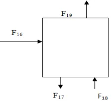
3.1.1.4 Stripper
Fig. 5. Material balance diagram for stripper
Table 5. Stripper input and output streams
Input streams Output streams
F16 F18 F17 F19
Comp Mole kmol/
hr
Mass kg/hr
Mole kmol/ hr
Mass kg/hr Mole kmol/ hr
Mass kg/hr
Mole kmol/hr
Mass kg/hr
NH3 - 0.02006 - - - 0.02006 - -
H2O 0.00000701 0.08406 - 0.00004326 - 0.1690 - 0.00004326
H2CO3 0.00118 0.000043 - - - -
Carbamate 0.00118 0.000053 - - - -
CO2 - - - 0.0005192 - 0.00055004
Total 0.104216 0.00004326 0.1896 0.0005933
3.1.1.5 Knock-Out Drum 2
Fig. 6. Material balance diagram for knock out drum 2
Table 6. Knock-out drum 2 input and output streams
Input streams Output streams
F21 F22 F23
Comp Mole/
wt
Mole kg/hr
Mass kg/hr Mole
kmol/hr
Mass kg/hr
Mole kmol/hr
Mass kg/hr
CO2 44 - 0.0005501 - 0.0005501 - -
H2O 18 - 0.00004326 - - - 0.00004326
Total 0.0005933 0.0005501 0.00004326
F22
F23
Nwokedi and Igbokwe; JERR, 5(1): 1-14, 2019; Article no.JERR.47628
3.2 Energy Balance Results
The conservation of energy differs from that of mass in that energy is generated (or consumed) in a chemical process. Material can change form; new molecular species was formed by chemical reactions where the total mass flow into a process unit must be equal to the flow out at the steady state [13]. The same is not true of energy. The total enthalpy of the outlet streams will not equal that of the inlet streams if energy is generated or consumed in the processed, such as that due to heat of reaction.
3.2.1 Energy balance summary tables
3.2.1.1 Absorber
Fig. 7. Energy balance diagram for absorber
Where Qp = heat of the process, in this case Qp = 0 (Adiabatic process)
Qr = Heat of the reaction = Σ- ΔHr0) Total heat input = H3 + H31 + H8 Total heat output = H5 + H4 + H41
ℎ , = ∫ ∈
3.2.1.2 Stripper
Fig. 8. Energy balance diagram for stripper
Table 7. Absorber energy balance summary
Energy Input (KJ/hr) Output (KJ/hr)
H3 0.1704 -
H4 - 0.3329
H41 - 0.1705
H8 3.9952 -
H5 - 102.4708
Qr 98.8085 -
Total 102.9741 102.9741
Table 8. Stripper energy balance summary
Energy Input (KJ/hr) Output (KJ/hr)
H16 47.4869 -
H18 0.1326 -
H17 - 127.77
H19 - - 76.5845
Qr - 98.805
Total 47.6195 - 47.6195
3.2.1.3 Gas Cooler 5
Fig. 9. Energy balance diagram for gas cooler 5
Table 9. Gas Cooler 5 energy balance summary
Energy Input (KJ/hr) Output (KJ/hr)
H20 5.0624 -
H21 - 2.5312
QVAP 0.09769 -
Q5 - 2.62889
TOTAL 5.16009 5.16009
3.2.1.4 Solution heat exchanger
Balance
H10 + H14 = H12 + H13
ASSUMPTIONS
(1) The reboiler only generate steam for desorption process.
(2) Regenerated amine solution does not pass through the reboiler so that H17 = H14 (3) That the energy recovery system is
dominant.
Table 10. Solution heat exchanger energy balance summary
Energy Input (KJ/hr) Output
(KJ/hr)
H10 102.4708 -
H12 - 182.7006
H13 - 47.5402
H14 127.77 -
Total 230.2408 230.2408
3.2.1.5 Solution Cooler 4
Fig. 11. Energy balance diagram for solution cooler 4
Hence Q4 = (H12 = H11) - H9
Table 11. Solution cooler 4 energy balance summary
ENERGY INPUT (KJ/hr) OUTPUT (KJ/hr)
H9 - 3.9952
H11 182.7006 -
Q4 - 178.7054
Total 182.7006 182.7006
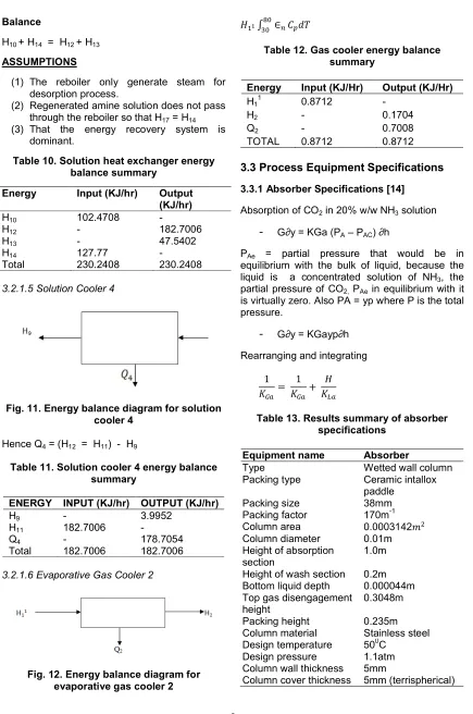
3.2.1.6 Evaporative Gas Cooler 2
Fig. 12. Energy balance diagram for evaporative gas cooler 2
∫ ∈
Table 12. Gas cooler energy balance summary
Energy Input (KJ/Hr) Output (KJ/Hr)
H11 0.8712 -
H2 - 0.1704
Q2 - 0.7008
TOTAL 0.8712 0.8712
3.3 Process Equipment Specifications
3.3.1 Absorber Specifications [14]
Absorption of CO2 in 20% w/w NH3 solution
- G∂y = KGa (PA – PAC) ∂h
PAe = partial pressure that would be in equilibrium with the bulk of liquid, because the liquid is a concentrated solution of NH3, the partial pressure of CO2, PAe in equilibrium with it is virtually zero. Also PA = yp where P is the total pressure.
- G∂y = KGayp∂h
Rearranging and integrating
1
= 1 +
Table 13. Results summary of absorber specifications
Equipment name Absorber
Type Wetted wall column
Packing type Ceramic intallox
paddle
Packing size 38mm
Packing factor 170m-1
Column area 0.0003142
Column diameter 0.01m
Height of absorption section
1.0m
Height of wash section 0.2m Bottom liquid depth 0.000044m Top gas disengagement
height
0.3048m
Packing height 0.235m
Column material Stainless steel
Design temperature 500C
Design pressure 1.1atm
Column wall thickness 5mm
Nwokedi and Igbokwe; JERR, 5(1): 1-14, 2019; Article no.JERR.47628
The design of wet scrubbers or any air pollution control device depends on the industrial process conditions and the nature of the air pollutants involved. Inlet gas characteristics and dust properties are of primary importance. Scrubber was designed to collect particulate matter and/or gaseous pollutants [3]. Wet scrubbers remove dust particles by capturing them in liquid droplets. Wet scrubbers remove pollutant gases by dissolving or absorbing them into the liquid [15]. Droplets that are in the scrubber inlet gas were separated from the outlet gas stream by means of another device referred to as a mist eliminator or entrainment separator.
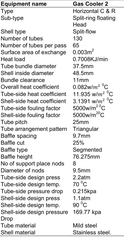
3.3.2 Evaporative Gas Cooler 2 specifications
Area of cooler A = Ǿ UΔζm
The evaporative cooler (also swamp cooler, desert cooler and wet air cooler) is a device that was designed to cool air through the evaporation of water. Evaporative cooling differs from typical air conditioning systems which use vapour-compression or absorption refrigeration cycles. Evaporative cooling works by employing water's large enthalpy of vaporization [16]. The temperature of dry air can be dropped significantly through the phase transition of liquid water to water vapour, which requires much less energy than refrigeration.
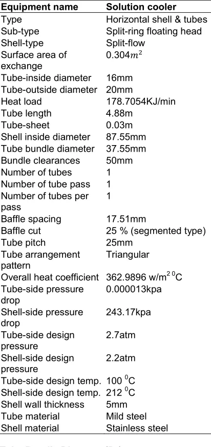
3.3.3 Solution Cooler 2 Specifications
Basic design equation [17]
= UAΔTm
Shell – Side Heat Transfer Coefficient
ℎ
= ℎ 0.33 ( ) .
hs = shell – side heat transfer coefficient, de = equivalent diameter
h = heat transfer correction factor, Re = Reynolds number, Pr = prandth number
= viscosity of fluid at mean temp, w = viscosity of fluid at wall temp.
(/w)0.14 = viscosity correction factor.
Overall Heat Coefficient
Kw for mild steel = 45w/m0C (Sinnott and Towler)
1
= 1
ℎ + 1 ℎ + 2 + 1 ℎ 1 ℎ
Shell – Side Pressure Drop
∆ = 8 (
2 )
.
Neglecting viscosity correction factor
From Fig. 12 (Coulson and Richardson)
f = 5.5 x 10⁻²
Table 14. Results summary of evaporative gas cooler 2 specifications
Equipment name Gas Cooler 2
Type Horizontal C & R
Sub-type Split-ring floating
Head
Shell type Split-flow
Number of tubes 130
Number of tubes per pass 65 Surface area of exchange 0.003m2
Heat load 0.7008KJ/min
Tube bundle diameter 37.5mm Shell inside diameter 48.5mm
Bundle clearance 11mm
Overall heat coefficient 0.082w/ 0C Tube-side heat coefficient 11.935 w/ 0C Shell-side heat coefficient 3.1391 w/ 0C Tube-side fouling factor 5000w/m2 0C Shell-side fouling factor 5000w/m20C Tube pitch 25mm Tube arrangement pattern Triangular Baffle spacing 9.7mm Baffle cut 25% Baffle type Segmented Baffle height 76.275mm No of support place nods 8
Diameter of nods 9.5mm
Tube-side design press 2.2atm Tube-side design temp. 70 0C Tube-side pressure drop 0.215kpa Shell-side design press 1.1atm Shell-side design temp. 90 0C Shell-side design pressure Drop
169.77 kpa
Tube material Mild steel
Shell material Stainless steel.
3.3.4 Cooler 5 (Condenser 5) Specifications
A = surface area of exchange.
Table 15. Results summary of solution cooler 2 specifications
Equipment name Solution cooler
Type Horizontal shell & tubes
Sub-type Split-ring floating head
Shell-type Split-flow
Surface area of exchange
0.304
Tube-inside diameter 16mm Tube-outside diameter 20mm
Heat load 178.7054KJ/min
Tube length 4.88m
Tube-sheet 0.03m
Shell inside diameter 87.55mm Tube bundle diameter 37.55mm
Bundle clearances 50mm
Number of tubes 1
Number of tube pass 1 Number of tubes per pass
1
Baffle spacing 17.51mm
Baffle cut 25 % (segmented type)
Tube pitch 25mm
Tube arrangement pattern
Triangular
Overall heat coefficient 362.9896 w/m2 0C Tube-side pressure drop 0.000013kpa Shell-side pressure drop 243.17kpa Tube-side design pressure 2.7atm Shell-side design pressure 2.2atm
Tube-side design temp. 100 0C Shell-side design temp. 212 0C Shell wall thickness 5mm
Tube material Mild steel
Shell material Stainless steel
Tube Bundle Diameter (Db)
= ( )
From Table 15 (Coulson and Richardson), for triangular pitch.
K1 = 0.175, ni = 2.285
Tube Inside Coefficient.
Cross – sectional area of one tube
= ( )
4
Shell – Side Heat Transfer Coefficient
ℎ = . ( ) .
where hs = shell – side heat coefficient, Kf = thermal conductivity of fluid
h = heat transfer coefficient, R = Reynolds number, Pr = prandth
0.14 = viscosity correction factor. w
Table 16. Results summary of cooler 5 (Condenser 5) specifications
Equipment name Cooler 5
Type Shell & tube H.E
Sub-type Split-ring floating head
Head load 2.62889kJ/min
Shell type Two shell pass
Number of tubes 1
Number of tubes pass 4 Number of tubes per pass
1
Tube bundle diameter 5.88mm Surface area of cooler 0.00245m2 Shell inside diameter 63.88mm
Baffle spacing 494mm
Baffle cut 25%
Baffle height 0.75 Ds = 47.91mm
Baffle type Segmented
Tube pitch 31.25mm
Tube pattern Triangular pattern
No of rods 12
Diameter of rods 9.5mm
Shell-side design press 5.984atm Tube-side design press 2.75atm Shell-side design temp. 3100C Tube-side design temp. 1600C
Shell material Stainless steel Overall heat coefficient 3.5142w/m20C Shell wall thickness 5mm
Shell cover thickness 5mm
Tube-side pressure drop 0.0000079kpa Shell-side pressure drop 791.388kpa.
3.3.5 Knock-Out Drum 1 Specification
Nwokedi and Igbokwe; JERR, 5(1): 1-14, 2019; Article no.JERR.47628
Table 17. Results summary of knock out drum 1 specification
Equipment name Knock-Out Drum I
Type Vertical vessel
Drum diameter 0.002m
Drum length 0.004m
Mist eliminator type Knitted wire-mesh
Mist eliminator thickness 0.152m
Clearance b/w liquid surface and centre of nozzle 0.3m Clearance b/w centre of inlet
Nozzle and mist eliminator
0.1524m
Clearance b/w mist eliminator and drum top edge 0.31m
Drum material of construction Stainless steel
Drum wall thickness 7mm
Head and closure type Ellipsoidal
Head and closure type 7mm
Mist eliminator material Stainless steel.
3.3.6 Knock-Out Drum 2 Specifications
Table 18. Results summary of knock out drum 2 specifications
Equipment name Knock-Out Drum 2
Type Vertical cylinder vessel
Drum diameter 0.002m
Drum length 1.0m
Mist eliminator type Knitted wire-mush
Mist eliminator thickness 0.152m
Liquid depth 0.1374m
Clearance b/w liquid surface and centre of nozzle 0.05m Clearance b/w the centre of nozzle and the mist eliminator 0.1m Clearance b/w the mist eliminator and drum top 0.31m
Drum wall thickness 5mm
Head and closure type Tom spherical
Head and closure thickness 5mm
Mist eliminate material Stainless
Drum material Stainless steel
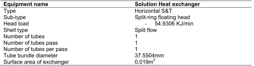
3.3.7 Solution heat exchanger specifications
A heat exchanger was designed for efficient heat transfer from one medium to another. The media is separated by a solid wall, so that they never mix, or they may be in direct contact. They are
widely used in space heating, refrigeration, air conditioning, power plants, chemical plants, petrochemical plants, petroleum refineries, natural gas processing, and sewage treatment [19].
Table 19. Results summary of solution heat exchanger specifications
Equipment name Solution Heat exchanger
Type Horizontal S&T
Sub-type Split-ring floating head
Head load - 54.9306 KJ/min
Shell type Split flow
Number of tubes 1
Number of tubes pass 1
Number of tubes per pass 1
Tube bundle diameter 37.5504mm
Equipment name Solution Heat exchanger
Shell inside diameter 87.5504mm
Baffle spacing 17.6mm
Baffle cut 25%
Baffle height 135mm
Baffle type Segmented
Tube pitch 25mm
Tube pattern Triangular pattern No of rods 8
Bundle diameter 124mm
Shell inside diameter 180mm
Tube outside diameter 20mm
Tube inside diameter 16mm
Tube length 4.88mm
Tube-sheet thickness 0.03m
Bundle clearance 50mm
Diameter of rods 9.5mm
Shell-side design press 1.1atm
Tube-side design press 1.1atm
Shell-side design temp. 1600C
Tube-side design temp. 3600C
Shell material Stainless steel
Overall heat coefficient 300w/m2 0C
Shell wall thickness 5mm
Tube -side coefficient 261.13w/m2 0C
Shell-side coefficient 361.324w/m2 0C
Shell cover thickness 5mm
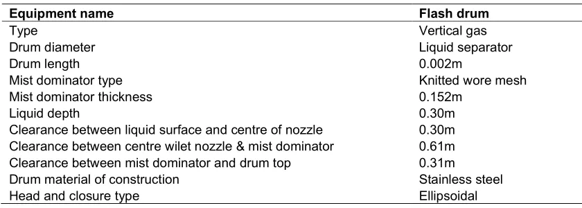
3.3.8 Flash drum specifications
Table 20. Results summary of flash drum specifications
Equipment name Flash drum
Type Vertical gas
Drum diameter Liquid separator
Drum length 0.002m
Mist dominator type Knitted wore mesh
Mist dominator thickness 0.152m
Liquid depth 0.30m
Clearance between liquid surface and centre of nozzle 0.30m
Clearance between centre wilet nozzle & mist dominator 0.61m
Clearance between mist dominator and drum top 0.31m
Drum material of construction Stainless steel
Head and closure type Ellipsoidal
3.3.9 Optimal values of CO2 and validation of the experimental data
Table 21. Optimum conditions for CO2 capture
Conc of solvent (Mol/dm3)
Contact time (Secs)
Volume of solvent (ml)
Predicted amount of CO2 (%)
Experimental
amount of CO2
(%)
Percentage error (%)
Nwokedi and Igbokwe; JERR, 5(1): 1-14, 2019; Article no.JERR.47628
The optimum conditions obtained are concentration of solvent 6.15 mol/dm3, contact time 59.21 seconds, volume of solvent 107.84 with 5.021 percent of CO2 absorbed as shown in Table 21. Table 21 also depicts the validation of the optimal results of the sequestration process by performing the experiment with predicted optimum conditions, from the table it can be observed that the percentage error between the actual and predicted was 2 percent, this showed that the model was adequate in predicting the response for the absorption of CO2.
4. CONCLUSION
The design of a plant to recover CO2 from spent air from aerobic fermentation was successfully carried out. Material and energy balances were carried out on each equipment and then over the entire process. These balances were used in the chemical and mechanical engineering design of the following equipment: absorber, knock out drum, flash drum, gas cooler, reboiler and stripping column. The data obtained in this design were used to fabricate an absorption column by the research for CO2 and CO capture. The empirical relationship between amount of CO2, CO captured and the independent variables were obtained with the aid of a statistical package. The statistical package was useful in analyzing and optimizing the amount of CO2 and CO captured. The Analysis of Variance (ANOVA) result for the model terms were obtained and were applied for estimating the significance of the model. The experimental data were also analyzed to ascertain the correlation between the experimental and predicted gases captured, normal probability and residual plot as well as actual and predicted plots while the 3D response surface plots were generated to estimate the effect of the combinations of the independent variables on the amount of the captured gases.
COMPETING INTERESTS
Authors have declared that no competing interests exist.
REFERENCES
1. Aroonwilas A, Veawab A. Integration of CO2 capture unit using single- and blendedamines into supercritical coal-fired power plants: Implications for emission and energymanagement. International Journal of Greenhouse Gas Control. 2007;1:143-150.
2. Zeng Q, et al. Mass transfer coefficients for CO2 absorption into aqueous ammonia solution using a packed column. Ind. Eng. Chem. Research. 2011;50:10168-10175. 3. Coulson JM, Richardson JF. Chemical
Engineering, Pergamon, N.Y. 1968;2. 4. Sadik, Kakac, Hongtan. Heat exchanges:
Selection, rating and thermal design. (2nd ed.) CRC Press; 2002.
5. Watson RT. Climate change. Synthesis Report, Cambridge University Press, UK; 2001.
6. Saunders EAD. Heat exchangers:
Selection design and construction. Longman; 1988.
7. Wiche IA, Kennedy RJ. Energy and fuels. 2002;14:56-66.
8. Lackuer D, Klaus S. Carbonate chemistry for sequestering fossil carbon. Annual Review of Energy and the Environment. 2002;27(1):193-232.
9. Liao CH, Liu WT, Tan CS. Removal of CO2 by absorption in a rotating packed bed. Ind. Eng. Chem. Res. 2003;42:2381-2386. 10. Nwokedi IC, Igbokwe PK. Absorption
kinetics and mass transfer coefficient for carbon (IV) oxide sequestration by ammonia solution. The Pharmaceutical and Chemical Journal. 2018;5(6):45-53. Available:http://tpcj.org/download/vol-5-iss-6-2018/TPCJ2018-05-06-45-53.pdf 11. Qing F, et al. Kinetics of CO2 absorption in
aqueous ammonia solution. International Journal of Greenhouse Gas Control. 2011;4(5):729-738.
12. Liao CH, Li MH. Kinetics of absorption of carbon (IV) oxide into aqueous solutions of
monoethanolamine +
N-methyloliethanolamin. Chem. Eng. Sci. 2002;57:4569-4582.
13. Aneke LE. Principles of chemical engineering process design. De-Adroil. Innovation Enugu; 2009.
14. Baum JA, Woehlck HJ. Interaction of inhalational anaesthetics with CO2 absorbents. Best Prac. Res., Clin. Anaesthesiol. 2003;17:63-76.
15. Kohl A, Nielsen B. Gas Purification. Fifth edition, Gulf Publishing Company, Houston, Texas; 1997.
16. Demontigny D, Tontiwachwuthikal P, Chakins A. Comparing the absorption performance of packed columns and membrane contactors. Ind. Eng. Chem. Res. 2005;44:5726-5732.
capture of carbon (iv) oxide from air. Chemical Engineering and Processing. 2006;45:1047-1058.
18. Mani F, Peruzzini M. CO2 absorption by aqueous NH3 solutions: Speciation of ammonium carbamate, bicarbonate and
carbonate by a CNMR study. Green Chem. 2006;8:995-1000.
19. Perry RH, et al. Chemical engineers. Handbook, 7th Edition, McGraw- Hill, News York. 1997; 244.
© 2019 Nwokedi and Igbokwe; This is an Open Access article distributed under the terms of the Creative Commons Attribution License (http://creativecommons.org/licenses/by/4.0), which permits unrestricted use, distribution, and reproduction in any medium, provided the original work is properly cited.
Peer-review history: