Recent Techniques in Echocardiography:
Two-Dimensional Echocardiography
KIRAN B. SAGAR, M.D.
Assistant Professor of Medicine, Division of Cardiology, and Director of Echocardiography, Medical College of Virginia, Health Sciences Division of Virginia Commonwealth University, Richmond, Virginia
Conventional M-mode echocardiography is a widely used noninvasive diagnostic tech-nique. It allows bedside assessment of cardiac chamber dimensions, valve motion and left ven-tricular function. The limitations of this tech-nique are that it (1) provides only a one-dimen-sional (icepick) view of the heart, (2) displays cardiac structures in an unfamiliar form that bears no resemblance to cardiac anatomy, and (3) does not provide information regarding spa-tial orientation of cardiac structures.
These limitations led to the development of two-dimensional (2-D) real-time echo-cardiography in the last decade. ,_4 The 2-D echo allows simultaneous visualization of car-diac structures in real time through multiple planes.
There are two types of commonly used 2-D echocardiography:
1 . Mechanical sector scanner. A single crystal transducer is mounted on a motor and oscillates in an arc of 30° .2 It is less
expensive than the phased array scanner and can be interphased with the existent M-mode echocardiograph. The disadvan-tages are noisiness, vibrations which the patient feels on the chest, and a narrow angle image. Newer, wide-angle mechan -ical sector scanners will overcome the las' problem.
2. Phased array wide-angle sector scan-ner. This technique requires multiple
ele-Correspondence and reprint requests to Dr. Kiran B.
Sagar, Box 51, Medical College of Virginia, Richmond, VA 23298.
58 / MCV OUARTERL Y 1 5(2):58-63, 1979
ments in the transducer and there is a se-ries of delays in the firing of the individual elements so that the ultrasonic wave front is at an angle to the transducer. By con-trolling the time sequence, the beam is electronically swept through a wide-angle sector.4
The patient is examined lying supine or in the left lateral position with head slightly ele-vated. The echo information is recorded on a video cassette which can be stored and re-played later. The figures shown here are still frames of the cine.
The cardiac imaging is done in the follow-ing multiple views:
1 . Parasternal long axis. The ultrasonic beam is parallel to the long axis of the left ventricle. Figure 1 is the anatomic section of the heart ob-tained in a presumed long axis plane of the left ventricle. Figure 2 shows the same structures seen with the 2-D echo. This view allows evalu-ation of pathology of the .aortic root, aortic valve, mitral valve, and left ventricle.
2. Parasternal short axis. This view is obtained by rotating the transducer through 90 ° and pro-vides tomographic sections of the heart from the apex of the left ventricle to the aortic root.
RIGHT VENTRICLE
POSTEROMEOIAL PAPILLARY
MUSCLE
CORONARY SINUS
RIGHT CORONARY CUSP
CUSP
"t.EFT VENTRICULAR
OUTFLOW TRACT
ANTERJOR MJTRAL
LEAFLET
LEFT ATRIUM
POSTERtOR MlTRAL LEAFLET
Fig 1-Anatomic section of heart obtained in presumed plane of long axis of left ventricle.
Fig 2-Long axis view of left ventricle with 2-D echo in a
normal subject. Head of subject towards right, feet towards
left, chest wall at the top, and spine at bottom of figure. An-terior· (AL) and posterior (PL) leaflets of mitral valve and
posteromedial papillary muscle (PM) are seen. RV = right
ventricle, LV = left ventricle, VS = ventricular septum, PW = posterior left ventricular wall, LA= left atrium, AV=
aor-tic valve.
3. Apical four-chamber view. This view is ob-tained by positioning the transducer over the point of maximal cardiac impulse with the
pa-tient in the left lateral position. The ventricles are
at the top and the atria at the bottom. Figures 8
and 9 are the diagrammatic and 2-D echo sec-tions of this view.
4. Suprasternal view. The transducer is in the
suprasternal notch and the ultrasonic beam
im-$(PTUM Pos~~tHAl PAP.lt.lARY t.lU$C,t
Fig 3-Anatomical section of heart along plane of ultra-sonic tomographic section at level of papillary muscles.
Fig 4-Ultrasonic tomographic section of left ventricle at
the level of papillary muscles (PM). Papillary muscles are
seen at approximately 3 and 8 o'clock positions. RV= right ventricle, LV = left ventricle, VS = ventricular septum, PW
= posterior left ventricular wall, LA= left atrium, AV= aor-tic valve.
MON
CORONARY
Fig 5-Still frame of sector scan of short axis tomographic
section of left ventricle at the level of mitral valve. In this
fig-ure, right ventricle is anterior and to the left. Left ventricle appears circular and is to the right. Anterior and posterior mitral leaflets have a fish mouth appearance during
dias-tole. RV = right ventricle, L V = left ventricle, VS =
ven-tricular septum, PW = posterior left ventricular wall, LA =
left atrium, AV= aortic valve.
Sf NUS
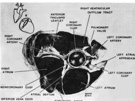
Fig 6-Anatomic section of heart obtained along presumed ultrasonic tomographic section at level of aortic valve.
Fig ?--Still frame of a tomographic section at level of aortic
valve. Aorta appears circular. Three leaflets of aortic valve
during diastole form a Y (R = right, L = left, N = non-coronary). Left atrial cavity is directly posterior to aortic root
and left atrial appendage (LAA) is towards right of figure.
Right atrium (RA) and tricuspid valve (TV) are on left of fig-ure. Right ventricular outflow (RVO) tract, pulmonic valve
(PV), and main pulmonary artery (MPA) are on top of figure.
Atrial septum (AS) is also seen.
ages the ascending aorta. This view is useful for
the diagnosis of coarctation of the aorta. 5
Contrast Echocardiography
Contrast echocardiography is of value in
detecting right-to-left shunt and tricuspid
regur-gitation. The usual contrast medium is a mixture
of 5 ml of normal saline and 2 ml of air which
are shaken together in a syringe to form mic
ro-cavities then injected into a peripheral vein. An
important precaution is to avoid injecting visible
air bubbles. Two ml of green dye produce
simi-lar results. Figure 1 0 shows opacification of the
right atrium, right ventricle, and pulmonary ar-tery, following an injection of normal saline in a
tomographic section at the level of the aortic
valve.
Clinical Application of 2-D Echocardiography
The 2-D echo is still in the developmental phase and further investigations are required to establish its accuracy, sensitivity, and
specific-ity. However, it has already made a significant
contribution in the assessment of the severity of
Fig 8-Left. Demonstration of placement of the transducer over apex and plane of tomogram. The image is displayed as if one were looking from below in the position of left hip, showing right and left atria (RA and LA) and right and left ventricles (RV and
LV). Right. Section of the normal heart shown as it appears on the picture at left cardiac apex at top. RA = right atrium, LA = left atrium, RV= right ventricle, LV = left ventricle.
BASE
Fig 9---Diagrammatic representation ( left) of apical image ( right). The right ventricle (RV) shows coarse trabeculation whereas the left ventricle (LV) is smooth. The tricuspid and mitral valves (TV and MV) are seen. The ventricular septum is seen between the two ventricles. The interatrial septum is seen between right and left atria (RA and LA).
mitral and aortic stenosis, regional and global
abnormalities of the left ventricular wall motion,
and congenital heart diseases.
Mitral Stenosis
Quantitative assessment of the mitral valve area with 2-D echo shows excellent
corre-lation with the mitral valve area obtained by car
-diac catheterization (r = 0.95)6 and at opera
-tion (r = 0.92).7
Fig 10- Tomographic section at the level of aorta, after in
-travenous injection of normal saline. Note opacification of right atrium (RA) and right ventricular outflow (RVO) tract. Pulmonic valve (PV). aorta (AO), and left atrium (LA) are also seen.
62 / SAGAR: ECHOCARDIOGRAPHY
Mitral Valve Prolapse and Flail Mitral Valve
Two-dimensional echocardiography has
accurately defined patterns of mitral valve
pro-lapse and flail mitral valve due to ruptured
chordae tendinae. 8
Aortic Stenosis
Two-dimensional echocardiography not
only localizes the level of aortic obstruction, that
is, valvular, subvalvular or supravalvular9 but
also allows noninvasive separation of significant from insignificant aortic stenosis. In our
labora-tory, patients with an aortic valve dia'meter of
<1 .3 cm (obtained in the long axis) and
con-centric left ventricular hypertrophy had a mean
aortic gradient of >50 mm Hg at cardiac ca the-terization. 1 0
Left Ventricular Wall Motion
Regional and global left ventricular wall
motion abnormalities can be studied
non-invasively. The 2-D echo provides an ultrasonic
angiogram of the left ventricle and thus left
ven-tricular volumes and ejection fraction can be
es-timated. At the present time we still need
valida-tion of the accuracies and inaccuracies of the
technique.
Coronary Artery Disease
echo-cardiography.11 Further investigations are
needed to define sensitivity and specificity of
this technique.
Congenital Heart Disease
Two-dimensional echocardiography
should prove helpful in delineating cardiac
anat-omy in critically ill infants who are at a high risk
for cardiac catherization as well as aid in the di-agnosis of lesions such as atrial septal defects, ventricular septal defects, A-V canal defects,
and transposition of great vessels.
In conclusion, the development of 2-D wide-angle echocardiography is a hallmark in the use of ultrasound as a diagnostic tool. It
al-lows simultaneous visualization of cardiac
struc-tures in real time through multiple planes
with-out known risk to the patient.
Figures 1 , 2, 3 ,4, 5, 6, 7, and 1 0 are reproduced by permission from Mayo Clinic Proceedings (53:271-303,
1978).
Figures 8 and 9 are reproduced from Circulation
(57:503-511, 1978) by permission of the American Heart Association, Inc.
REFERENCES
1. KING DL: Cardiac ultrasonography. Cross-sectional ul-trasonic imaging of the heart. Circulation 4 7: 843-847, 1973.
2. GRIFFITH JM, HENRY WL: A sector scanner for real time two-dimensional echocardiography. Circulation
49:1147-1152, 1974.
3. VON RAMM OT, THURSTONE FL: Cardiac imaging using a phased array ultrasound system. I. System design.
Circulation 53:258-262, 1975.
4. KISSLO J, VON RAMM OT, THURSTONE FL: Cardiac imaging using a phased array ultrasound system. II. Clinical
technique and application. Circulation 53:262-267, 1975.
5. WEYMAN AE, CALDWELL RL, HURWITZ RA, ET AL: Cross-sectional echocardiographic detection of aortic ob-struction. Coarctation of aorta. Circulation 57: 498-502, 1977.
6. HENRY WL, GRIFFITH JM, MICHAELIS LL, ET AL: Measure-ment of mitral orifice area in patients with mitral valve
disease by real-time, two-dimensional
echo-cardiography. Circulation51 :827-831, 1975.
7. NICHOL PM, GILBERT BW, KISSLO JA: Two-dimensional echocardiographic assessmeni or mitral stenosis.
Cir-culation 55: 120-1 28, 1 977.
8. GILBERT BW, SCHATZ RA, VON RAMM OT, ET AL: Mitral valve prolapse. Two-dimensional echocardiographic and angiographic correlation. Circulation 54: 716-723, 1976.
9. WILLIAMS DE, SAHN DJ, FRIEDMANN WF: Cross-sectional echocardiographic localization of sites of left ventricu-lar outflow tract obstruction. Am J Cardiol
37:250-255, 1976.
10. SAGAR KB, Cox LH, ROMHILT OW: Two-dimensional echocardiography in evaluation of aortic stenosis in the older patient, abstract. Clin Res 26:752A, 1978.
11. OGAWA S, HUBBARD FE, PAULEL FJ, ET AL: A new
ap-proach to noninvasive left coronary artery visualization
using phased array crossectional echocardiography, abstract. Circulation 58:11-189, 1978.