RIZVI COLLEGE OF ENGINEERING
EXTC DEPARTMENT
SUBJECT: TNM
LMR
Q1) Compare between SNMP v1, SNMP v2 and SNMP v3.
Content SNMPv1 SNMPv2 SNMPv3
Standards RFC-1155.1157.1212 1441,1452 RFC-1909.1910 RFC- 1901 to 1908
RFC-1902 to 1908,2271 to 2275
Version SNMPv1 was the first version of SNMP SNMPv2 currently exists in at least three flavors, SNMPv2c, SNMPv2u, and SNMPv2
SNMPv3 is the newest version of SNMP.
protocol operations
Simple request/ response protocol. Protocol operations :Get, GetNext, Set, and Trap
Similarity: Get, GetNext, Set Changes: Trap message format New protocol operations GetBulk and Inform
Content SNMPv1 SNMPv2 SNMPv3
Security No security from someone with access to the network
SNMPv2 failed to improve on security.
Its primary feature is enhanced security.
Complexity Performance and security limitations. More powerful but more complex than SNMPv1
SNMPv3 focuses on improving the security aspect.
Message Format
Five
messages(GetRequest,,GetNextRequest, SetRequest, Trap, Response)
Seven messages instead of five (inform-request, get-bulk-request)
Implements SNMP v1 and v2 specifications along with proposed new features.
Content SNMPv1 SNMPv2 SNMPv3
protocol identifies each SNMP entity.
MIB Defines limited, easily implemented MIB of scalar variables and two dimensional tables
Defines general framework with which MIB defined and constructed
Can configure agents to provide a number of levels of access to MIB
Encrypted
traffic, Detection of malformed packets
No Yes Yes
Susceptible to brute- force attacks,
Susceptible to buffer-overflow
Content SNMPv1 SNMPv2 SNMPv3
attacks
Susceptible to injection attacks
Yes No No
Q2) List & describe SNMP command with syntax?
Command Syntax Explanation
DISABLE SNMP disable snmp Enter this command to disable SNMP and all SNMP related commands. Be default, SNMP is disabled.
Command Syntax Explanation
commands. By default, SNMP is disabled.
SET SNMP
TRAPCOMMUNITY
set snmp
trapcommunity {<"Trap community string">}
Enter this command to set the trap community string. By default, the value is “COMPAQ”.
SET SNMP TRAPDEST
set snmp trapdest {,1 / 2 / 3 } {[none] / []}
Enter this command to set up to three SNMP trap
destinations. Trap destinations cannot be FQDN addresses, you must use IPv4 addresses only. Specify none to remove a trap destination..
SHOW SNMP show snmp Enter this command to show all SNMP configuration settings.
TEST SNMP test snmp Enter this command to send a test trap to all of the configured trap destinations. The command sends a
Command Syntax Explanation
descriptions.
Q3) what is SNMP v3 MIB, message format, architecture, engine ID, security
services?
SNMP v3 MIB:
i) Figure1 shows the MIB of the new object groups. They are nodes under snmpModules.
ii) There are seven new MIB groups. The snmpFrameworkMlB, node 10 under snmpModules, describes the SNMP
iii) There are three groups defined under snmpModules for applications. They are snmpTargetMIB (node 12), snmpNotificationMIB (node 13), and snmpProxyMIB (node 14).
Message Format:
Msg Version: Syntex – Integer, Size (bytes) – 4 Message Version Number: Describes the SNMP version number of this message; used for ensuring compatibility between versions. For SNMPv3, this value is 3.
MsgID :Syntax-Integer, Size (bytes) – 4 Message Identifier: A number used to identify an SNMPv3 message and to match response messages to request messages.
Msg Max Size: Syntax -Integer,Size (bytes) – 4 Maximum Message Size: The maximum size of message that the sender of this message can receive. Minimum value of this field is 484.
Msg Flags: Syntax - Octet String, Size (bytes) – 1
Msg Security Model: Syntax -Integer, Size (bytes) – 4 An integer value indicating which security model was used for this message. For the user-based security model this value is 3.
Msg Security Parameters: Size (bytes) –Variable Message Security Parameters: A set of fields that contain parameters required to implement the particular security model used for this message.
Scoped PDU: - Size (bytes) – Variable
Architecture:
The architecture of an SNMP entity is defined as the elements of an entity and the names associated with them. There are three kinds of naming: naming of entities, naming of identities, and naming of management information.
Elements of an Entity:
The elements of the architecture associated with an SNMP entity, shown in Figure4, comprise an SNMP engine and a set of applications. The SNMP engine, named snmpEnginelD, comprises a dispatcher, message processing subsystem, security subsystem, and an access control subsystem.
SNMP Engine: i) As shown in Figure4, an SNMP entity has one SNMP engine, which is uniquely identified by an
snmpEnginelD. The SNMP engine ID is made up of octet strings. The length of the ID is 12 octets for SNMPvI and SNMPv2, and is variable for SNMPv3.
iii) The fifth octets for SNMPv l and SNMPv2 indicate the method that the enterprise used for deriving the SNMP engine ID and 6-12 octets function of the method.
iv) For a simple entity, it could be just the IP address of the entity. The fifth octet of the SNMPv3 engine ID indicates the format used in the rest of the variable number of octets.
security services :
The security subsystem provides security services at the message level in terms of authentication and privacy protection. The access control subsystem provides access authorization service.
Q4) What are the limitations of SNMP v1?
Limitations of SNMP v1
i. SNMP has issues with SNMP request handling and with SNMP trap handling in both agents and managers.
ii. In essence, the advisory said what everybody everywhere already knew: that SNMPv1 is insecure and its use can expose system to exploitation.
iii. It further found specific vulnerabilities for a limited set of SNMP agents that could lead to DOS attacks, buffer under run exploits, and other nastiness.
iv. The source of these was found to be in the vendor-specific functions written to parse ASN.1 formatted MIB definitions, but fortunately not in ASN.1 itself.
vi. SNMP PDU size limitations: This is a concern when using data collections. When there are many collections configured, there may be excessive fragmentations attributable to NNM SNMP operations. An implementation of this [SNMP] protocol need not accept messages.
vii. SNMP may not be suitable for the management of truly large networks because of the performance limitations of polling. viii. SNMP is not well suited for retrieving large volumes of data, such as an entire routing table.
ix. SNMP traps are unacknowledged & may not be delivered.
x. SNMP provides only trivial authentication i.e. it is suitable for monitoring rather than control.
xi. SNMP does not support explicit actions i.e., an action is taken by changing a parameter or setting an object value (indirectly).
xii. SNMP does not support manager-to-manager communications. Limited errors codes
Limited notifications
o Limited performance
o Transport dependence
o Lack of hierarchies
o Lack of security
Q5) Explain user security model of SNMPV3.
RFC 2274 defines the user-based security model (USM) for SNMPv3. This specification encompasses:
Authentication: Provides data integrity and data origin authentication. The message authentication code HMAC, with either the hash function MD5 or SHA1 provides authentication.
Privacy: Protects against disclosure of message payload. The cipher block chaining (CBC) mode of DES is used for encryption.
Message format: Defines format of msg Security Parameters field, which sup-ports the functions of authentication, timeliness, and privacy.
Discovery: Defines procedures by which one SNMP engine obtains information about another SNMP engine. Key management: Defines procedures for key generation, update, and use.
USM Security Parameters:
Usm Security Parameters that specifies the internal format of the msg Security Parameters field in SNMPv3 message.
Authoritative SNMP Engine:
In any message transmission, one of the two entities, transmitter or receiver; is designated as the authoritative SNMP engine, according to the following rules.
When an SNMP message contains a payload which expects a response, then the receiver of such messages is authoritative.
When an SNMP message contains a payload which does not expect a response (for example a SNMPv2-Trap, Response, or Report PDU), then the sender of such a message is authoritative.
Thus, for messages sent on behalf of a Command Generator and for Inform messages from a Notification Originator, the receiver is authoritative.
User Security model security parameters definition
This designation serves two purposes. The first one is,
i. The timeliness of a message is determined with respect to a clock maintained by the authoritative engine.
ii. When an authoritative engine sends a message (Trap, Response, Report), it contains the current value of its clock, so that the non-authoritative recipient can synchronize on that clock.
iii. When a non-authoritative engine sends a message (Get, GetNext, GetBulk, Set, Inform), it includes its current estimate of the time value at the destination, allowing the destination to assess the message's timeliness.
The second one is,
ii. It makes sense to designate the receiver of Command Generator and Inform PDUs as the authoritative engine, and therefore the possessor of the authoritative clock in an exchange.
iii. If a response or trap is delayed or replayed, little harm should occur. However, Command Generator and, to some extent, Inform PDUs result in management operations, such as reading or setting MIB objects. Thus, it is important to guarantee that such PDUs are not delayed or replayed, which could cause undesired effects.
1. Elements of Usm Security Parameters :
When an outgoing message is passed to the USM by the Message Processor, the USM fills in the msg Security Parameters field. When an incoming message is passed to the USM by the Message Processor, the USM processes the values contained in msg Security Parameters.
The security parameters field consists of the following elements:
MsgAuthoritativeEngineID: The snmpEnginelD of the authoritative SNMP engine involved in the exchange of this message. Thus, this value refers to the source for a Trap, Response, or Report, and to the destination for a Get, GetNext, GetBulk, Set, or Inform.
MsgAuthoritativeEngineBoots: The snmpEngineBoots value of the authoritative SNMP engine involved in the exchange of this message. The object snmpEngineBoots is an integer in the range 0 through
2
31−1
231−1 thatrepresents the number of times that this SNMP engine has initialized or reinitialized itself since its initial configuration. MsgAuthoritativeEngineTime: The snmpEngineTime value of the authoritative SNMP engine involved in the
exchange of this message. The object snmpEngineTime is an integer in the range 0 through
2
31−1
231−1 thatrepresents the number of seconds since this authoritative SNMP engine last incremented the snmpEngineBoots object. Each authoritative SNMP engine is responsible for incrementing its own snmpEngineTime value once per second. A non-authoritative engine is responsible for incrementing its notion of snmpEngineTime for each remote authoritative engine with which it communicates.
MsgUserName: The user (principal) on whose behalf the message is being exchanged.
MsgPrivacyParameters: Null if privacy is not being used for this exchange. Otherwise, this is a privacy parameter. For the current definition of USM, the privacy parameter is a value used to form the value (IV) in the DES CBC algorithm.
Q6) What is SNMP proxy server?
SNMP Proxy Server:
i. The SNMPv2 proxy server configuration is shown in Figure12.
ii. The requests to and responses from, as well as traps from, SNMPv2 agents are processed by the SNMPv2 manager with no changes.
iii. A proxy server is implemented as a front-end module to the SNMPv2 manager for communication with SNMPv1 agents.
SNMP Proxy Server Configuration
iv. Figure13 details the conversions that are done by an SNMP v2—v1 proxy server.
vi. There are two modifications done to the GetBulkRequest PDU. The values for the two fields, non-repeaters and max-repetitions, are set to zero and transmitted as GetNextRequest PDU.
vii. The GetResponse from SNMPvI is passed through unaltered by the proxy server to the SNMPv2 manager, unless a response has a tooBigError value.
Q7) Draw describe with neat diagram SNMPv1 PDU format
• Simple Network Management Protocol i.e. SNMP is a simple request/response protocol in which SNMP manager communicates with SNMP agents/managed devices using SNMP PDU’s (Packet Data Unit).
• These PDUs are encapsulated in SNMP Messages.
• An snmp message consists of a sequence that contains SNMP version, Community String, and SNMP PDU and an SNMP PDU forms the body of the message
• SNMP Message is different from SNMP PDU 1. SNMPv1 PDU Format
• For SNMPv1, there are two PDU formats, one for Trap and other for rest of the PDU types. • Below PDU format is applicable for Get, GetNext, Set and Response PDUs:
• PDU Type – Specifies the type of PDU
• Request ID – Associates SNMP requests with responses.
• Error status – Indicates one of a number of errors and error types. It is set only in Response PDU, for rest it is set as 0. • Error index – Associates an error with a particular object instance. It is set only in Response PDU, for rest it is set as 0. • Variable bindings – Each variable binding associates a particular object instance with its current value. For Get and GetNext requests, the value is ignored.
• PDU Type – Specifies the type of PDU as Trap
• Enterprise – Identifies the management enterprise under whose registration authority the trap was defined. • Agent address – IP address of the agent
• Generic trap type – Used to identiy the generic trap. There are six types of generic traps. • Specific trap type – Used to identify a specific trap.
• Time Stamp – Value of the sysUpTime mib object 1. SNMPv2 PDU Format
• For SNMPv2, there are two PDU formats, one for GetBulk and other for rest of the PDU types. • Below PDU format is applicable for Get, GetNext, Set, Response, Trap and Inform PDUs:
• PDU Type- Specifies the type of PDU
• Request ID- Associates SNMP requests with responses.
• Error Status- Indicates one of a number of errors and error types. It is set only in Response PDU, for rest it is set as 0. • Error Index- Associates an error with a particular object instance. It is set only in Response PDU, for rest it is set as 0. • Variable Bindings- Each variable binding associates a particular object instance with its current value. For Get and GetNext requests, the value is ignored.
• PDU Type – Specifies the type of PDU as GetBulk • Request ID- Associates SNMP requests with responses.
• Non repeaters- Specifies the number of object instances in the variable bindings field that should be retrieved no more than once from the beginning of the request.
• Max repetitions- Defines the maximum number of times that other variables beyond those specified by the Non repeaters field should be retrieved.
• Variable Bindings- Each variable binding associates a particular object instance with its current value. 1. SNMPv3 PDU Format
• The PDU types for SNMPv3 are the same as the SNMPv2.
Q8) Describe the capability of RMON2 in Enterprise network management.
. RMON1 only provides visibility into the data link and the physical layers; potential problems that occur at the higher layers still require other capture and decode tools.
ii. Because of RMON1's limitations, RMON2 was developed to extend functionality to upper-layer protocols. RMON2 provides full network visibility from the network layer through to the application layer.
iv. With visibility into the upper-layer protocols, the network manager can monitor any upper-layer protocol traffic for any device or subnet in addition to the MAC layer traffic.
v. RMON2 allows the collection of statistics beyond a specific segment's MAC layer and provides an end-to-end view of network conversations per protocol.
vi. RMON2 is an extension of RMON that focuses on higher layers of traffic above the Medium Access Control (MAC) layer. vii. RMON2 has an emphasis on IP traffic and application-level traffic. RMON2 allows network management applications to monitor packets on all network layers.
viii. This is difference from RMON which only allows network monitoring at MAC layer or below. RMON2 is intended to be used by network monitoring applications. It is not intended to be used by human.
ix. The network manager can view conversations at the network and application layers. Therefore, traffic generated by a specific host or even a specific application (for example, a Telnet client or a web browser) on that host can be observed. x. Each monitored object must have a name, a syntax, an access-level, and an implementation-status. The name is used to identify the monitored object.
xi. The name has an object type and an object instance. Usually, the name is a text string for human to read. The syntax is the structure defined using ASN.1 notation. This abstract structure helps the human to understand the monitored object.
xii. The access-level means whether the monitored object can be read, written or both. Implementation-status is the status of the actual object. There are four possible values: mandatory, optional, obsolete, or deprecated.
RMON2 Groups :
RMON groups that were added when RMON2 was introduced, include the following: Protocol Directory: Provides the list of protocols that the device supports Protocol Distribution: Contains traffic statistics for each supported protocol Address Mapping: Contains network layer-to-MAC layer address mappings
Network Layer Matrix: Contains network layer traffic statistics for conversations between pairs of hosts Application Layer Host: Contains statistics for the application layer traffic to or from each host
Application Layer Matrix: Contains application layer traffic statistics for conversations between pairs of hosts User History Collection: Contains periodic samples of user-specified variables
Probe Configuration: Provides a standard way of remotely configuring probe parameters, such as trap destination and out-of-band management
These hold information related to higher-layer activities, such as statistics of traffic carried between specific host pairs for a given application.
These groups provide statistics on the amount of traffic between pairs of hosts, and contain statistics relating to the network layer and the application layer.
Advantages of RMON2 :
i. RMON2 is developed to provide a capability of monitoring protocol traffic above the MAC level. RMON2 operates upward from the network layer to the application layer. It can monitor traffic at the network layer, including IP addressing, and at the application level, such as email, ftp, and web.
ii. As a result, RMON2 can determine source or destination addresses beyond a router. This additional capability enables a network manager to determine such things as which nodes are contributing to the bulk of traffic that is incoming or outgoing to the LAN.
iii. It also enables a breakdown of traffic by protocol or application. The RMON2 MIB introduces an additional nine groups of variables to that of the RMON 1 MIB.
iv. The RMON2 brings benefits to the interoperability between independently developed solutions by moving up the protocol stack to analyze the network-and application-layer traffic.
vi. RMON2's capabilities include higher layer statistics, address translation (binding between MAC-layer addresses and network-layer addresses), configurable historical data studies, improved filtering, and remote probe configuration.
vii. The protocol directory of RMON2 supports a simple and interoperable scheme to establish associations with other RMON2 agent implementations. This protocol directory feature allows RMON applications to:
Define an open, extensible structure for collecting the traffic, host, and matrix data for each protocol and application. Map the data collected by a probe to the correct protocol name that can then be displayed at the network manager.
Q9) Discuss Ml, M2 and M4 interface in ATM network management. (DEC 2018 10M)
i. The ATM Forum interface reference architecture identifies a series of management interfaces numbered Ml through M5. ii. M1 and M2 are the interfaces between a private NMS and either an end user or a private network, respectively. The end user can be a workstation, ATM switch, or any ATM device. A private ATM network is an enterprise network.
iii. A private network management system can access its own network-related information in a public network via an M3 interface to the public network management system.
iv. The public NMS responds to the private NMS via the M3 interface with the relevant information or takes the action requested.
v. The M4 interface is between the public NMS and the public network. The final interface, M5, is between the NMSs of two service providers. The ATM Forum has not yet specified this interface.
The ATM Forum Management Interface Reference Architecture
The ATM Forum Management Model:
i. The Network Management Working Group of the ATM Forum has developed an end-to-end generic management model that encompasses private and public networks and lays out standards for interworking between them.
ii. The model defines gateways between SNMP and CMIP systems, and between standards-based and proprietary systems. iii. Five key management interfaces are defined in this model, labelled M1-M5.
iv. M1 is concerned with the management of the end-user equipment connecting to either private or public switches. v. M2 undertakes management of private ATM switches and networks. Private ATM network management is addressed through M1 combined with M2. M4 deals with their public ATM switches and networks. M3 is the link between
vii. Finally, M5 supports interactions between any two public networks. The definition of these interfaces allows a complete management service, ranging from a global view of the network (M5 management interface) to the management of individual elements (M1 management interface).
viii. In some cases, several management interfaces use the same information from a management information base (MIB) tree, see Table1.
Types Interaction Purpose Services Protocol
M1 CPE / NMS Management of user terminal equipment
- SNMP
M2 P-Switch / NMS Management of the ATM private network
Similar to M4 SNMP
M3 NMS / NML Management interaction between private and public domains
i.,Public network configuration and status gathering., ii.,Add & deletion of pre-authorized VCs., iii.new connection request
Types Interaction Purpose Services Protocol
M4 NML / EML or,EML / NE
Management of NE's and EMLs
i.,Fault and performance management, ii.,Configuration and circuit
provisioning, iii.,accounting
CMIP,(Q3),or SNMP
M5 NML / NML Management interaction between different owned public domains
Cross public network management No standard yet
ILMI Private/public Service control Service activation, service assurance (maintenance), usage metering (performance, billing)
ILMI - SNMP
Table1: Management Interface
M1 Interface: Management of ATM Network Element
SNMP ATM Management (M1 Interface)
ii. Four entities, ifInNUcastPkts, ifOutNUcastPkts, ifOutQLen, and ifspecific have been deprecated. The interfaces (interfaces) and ifMIB (IF MIB) groups under the mgmt. node.
M1/M2 Interfaces and the ILMI Implementation:
i. Interim Local Management Interface (ILMI), which is an implementation of the M I /M2 interfaces, enables the exchange of status, configuration, accounting and control information between any two ATM devices - such as two ATM switches - across a user-to-network interface (UNI).
ii. For ILMI to function, every ATM switch or network terminator and every ATM network that deploys a public or private network UNI must be equipped with a UNI Management Entity (UME) which supports an ILMI MIB.
iii. Two adjacent (or peer) UMEs can communicate using the common attributes provided by the ILMI.
v. The ILMI has been deployed by some vendors to perform management tasks across the UNI for some devices. However, since the ILMI provides a solution that is applicable only at the UNI, it cannot support the management tasks that are involved in a network comprising a range of ATM devices.
M4 Interface: Public Network Management
i. The management of public ATM network is primarily the responsibility of network service providers, carriers and Postal Telephone and Telegraph (PTT) companies.
ii. They have the challenge of not only managing the public network, but also keeping up with new technology.
Q10) In a network if 3Com router is added by one of the department, what updates
will happen in MIB and will SMI be accessed during this process? (Dec 2018 5M)
n a n/w of 3 com router is added by one of the department, what updates will happen in MIB and SMI be accessed during this process.
The manager would recognize the addition of a new component to the network by the periodic broadcast ping of the network by the manager. However, it would not know what component has been added until the MIB information on the 3 com hub is added to the managers MIB.
Q11) Discuss eTOM business framework with reference to Level 0, Level 1 and
Level 3 processes. (Dec 2018 10M)
Physical architecture of telecom management network
TMN architecture: There are three architectural perspectives: functional, physical, and information, as shown in Figure1. • The functional architecture identifies functional modules or blocks in the TMN environment, including the reference point between them. The requirements for interface are specified.
• The physical architecture defines the physical blocks and interfaces between them.
Physical Architecture: (Dec 2018 10M)
i. Model for the TMN physical architecture, shown in Figure3. A TMN physical block could be an embodiment of one or more blocks, besides its equivalent function block. For example, an operations system could have its operation function as well as mediation device, which does filtering of information.
ii. There are five types of physical blocks representing the five functions discussed. Operations systems are embodiments of TMN OSF. It is connected to the mediation device, placing the MF on a data communication network.
iii. The data communication network is the physical implementation of DCF, which to repeat, is not a function block, but a TMN function, DCF. The network elements, Q adapter, and workstations reflect their respective TMN functions
iv. The Q, F, and X TMN interfaces between the physical devices are also shown in Figure, representing the physical
implementation of the respective TMN reference points. The Q3 interface is used between the OS and either an NE or a QA. v. The Qx interface is shown between MD and QA/NE. An example of this would be an MD being a proxy server
Q12) What are the challenges of IT manager? (DEC 2018) 5 MARKS
Top challenging activities in managing the network:
• Rapid advance of technology
• Problem analysis—needs human intuition and skill besides sophisticated management tools • Anticipate customer demands
• Acquire and retain human resources
• Manage client–server environment in converged networks
• Networking with emerging technology necessitates the need for continuing education • Collaborative research between academic institutions and industry
• Maintain reliability, that is, make changes, upgrades, etc. without disrupting the network and impacting business • Diagnose problems or outages in a non-disruptive manner (without impacting other users on the network)
• Estimate the value of a technology transition.
Managing network without an NMS:
• Reactively, not proactively; fire fighting • Troubleshooting tools, e.g., sniffer, ping, etc
• Home-grown systems using an open source, e.g., Multi Router Traffic Grapher (MRTG) • Rely on consultant advice and technical information for growth decisions
Problems expected the NMS to resolve:
• Turn-around shorter for resolution of problems
• Gather statistics and predict trends for planning purposes • Document events, Trouble-shooting
• Remove constraints and bottlenecks, Fault isolation
• Expect the NMS to do a root cause analysis and pinpoint failures
Q13) What is Broadband Network Management?
As new technologies emerge, service providers offer new services to commercial and residential communities using those technologies. In turn, offering of new services by service providers is propelling information technology to new heights. This is especially true in broadband technology.
o The broadband network and the narrowband Integrated Services Digital Network (ISDN) are multimedia networks that provide integrated analog and digital services over the same network. Narrowband ISDN is low bandwidth network that can carry two 56 kilo baud rate channels. The broadband network can transport very high data rate signals. The narrowband ISDN is also known as Basic ISDN.
o There are three types of information technology services: voice, video, and data. In the traditional terminology, voice and video services are transported over the telecommunication network.
o One of the chief characteristics of broadband service is the integration of voice, video and data services over the same transportation medium, in other words, it is multimedia transportation networking. Sometimes, the broadband network is confused with high-speed data network, either dedicated or combined with real-time voice or video,
multimedia service of voice, video and data. The broadband network is also called the Broadband Integrated Services Digital Network (B-ISDN).
o The broadband network and service have contributed significantly to advances in three network segments of WAN, access network and home/customer premises equipment (CPE) network. In the WAN segment, protocols used in addition to IP are the asynchronous transfer mode (ATM), the Synchronous Optical Network (SONET) the
o Broadband access technology is implemented using one of five technologies.
Hybrid fiber coax (HFC) or cable modem technology is a two-way interactive multimedia communication system using fiber and coaxial cable facilities and cable modems.
The second technology uses a digital subscriber line (DSL). There are several variations of implementing this, generically referred to as xDSL.
The third and fourth technologies use wireless transmission from the switching office or the head end to the customer premises. Transmission in the two cases is either terrestrial or via a satellite.
The fifth technology is the mobile wireless technology. Mobile wireless technology is deployed as either access technology using GSM (Global System for Mobile Communications), GPRS (General Packet Radio Service) or CDMA (Code Division Multiple Access) or as a home/CPE network using WiFi (IEEE 802.3) protocol.
o Figure shows a broadband network. The WAN is MPLS/IP/ATM. The WAN is linked to the customer premises using either optical links, OC-n (Optical Carrier-n)/STS (Synchronous Transport Signal), or a broadband link with emerging access technology (HFC, xDSL, wireless). The customer network consists of two classes, residential customers and corporate customers with campus like network. The residential customers are either residential homes or small corporations that use broadband services, but do not require the high-speed access network to WAN. Corporate customers need high-speed access and connect optical or synchronous (E1/T1) links.
o Radio, video (television), Internet Service Provider (ISP), and other service providers constitute the service providers. Multiple services are multiplexed at the central office or the Multiple Service Operator (MSO) head end and are piped to the customer premises via common facilities. The service providers interface with WAN via gateways.
Q14) Define network management. State goals of network management.
A network management system (NMS) is a set of hardware and/or software tools that allow an IT professional to supervise the individual components of a network within a larger network management framework.
• Network management system components assist with:
1. Network device discovery - identifying what devices are present on a network.
2. Network device monitoring - monitoring at the device level to determine the health of network components and the extent to which their performance matches capacity plans and intra-enterprise service-level agreements (SLAs).
3. Network performance analysis - tracking performance indicators such as bandwidth utilization, packet loss, latency, availability and uptime of routers, switches and other Simple Network Management Protocol (SNMP) -enabled devices. 4. Intelligent notifications - configurable alerts that will respond to specific network scenarios by paging, emailing, calling or
texting a network administrator.
• We define network management as management of the network comprising nodes and links, and system management as
managing system resources, such as central processor usage, disk usage, and application processes. Service management deals with services provided by organizations to customers. Service management is an extension of network and systems.
• Network management includes the deployment, integration and coordination of the hardware, software and human elements to monitor, test, poll, configure, analyze, evaluate the network resources to meet the real-time, operational performance and QoS requirements at a reasonable cost.
Goals of N/W Management:
• The goal of network management is to ensure that the users of network are provided IT services with a quality of service that they expect.
• Toward meeting this goal, the management should establish a policy to either formally or informally contract an SLA with users. • From a business administration point of view, network management involves strategic and tactical planning of engineering, operations, and maintenance of network and network services for current and future needs at minimum overall cost.
• There needs to be a well-established interaction between the various groups performing these functions. • Figure presents a top-down view of network management functions. It comprises three major groups: (a) Network and service Provisioning,
(b) Network service Operations
(c) Network I & M (Installation & Maintanance)
• The Customer Relations group deals with clients and subscribers in providing services planned and designed by the Engineering group.
• Network I&M is the primary responsibility of the Plant Facilities group.
• Normal daily operations are the function of the Network Operations group, which controls and administers a NOC. This is the nerve center of network management operations.
• The functions of NOC are primarily concerned with network operations: its secondary responsibilities are network provisioning and network I & M.
• The associated service operations are handled by a subscriber operation center (SOC) and customer relations management (CRM). Our focus here is on NOC.
Q15) With respect ISO/OSI Network management describe following terms: (i) ACSE
(ii) ROSE (iii) Scoping and Filtering (iv) Linked Replies (v) CMIS/CMIP
ROSE:
The Remote Operation Service Element (ROSE) is the ISO equivalent of remote procedure call. ROSE allows the invocation of an operation to be performed on a remote system. The Remote Operation protocol contains an invoke identifier for correlating requests and responses, an operation code, and an argument field for parameters specific to the operation. ROSE can only be invoked once an application association has been established. CMIP uses the transaction-oriented services provided by ROSE for all its requests and responses. CMIP also uses the error response facilities provided by ROSE.
Scoping:
Scoping is meant to be understood in terms of the containment hierarchy. A position at a certain level of the containment tree is defined by the CMIS Managed Object Class parameter. The CMIS Scope parameter is then interpreted relative to this "base" managed object. The Scope parameter can be used to select the base object alone, all managed objects in the entire subtree (of the containment tree) below the base object, or all managed objects in the "n"th level (n = 1, 2, 3,...) below the base object.
Filtering:
Within the objects selected as a result of the scope parameter, it is possible to further refine the selection of managed objects through the use of filtering. Filtering provides the ability to select a subset of these objects based on conditions applied to attribute (e.g., IP routing table entries with the "ipRouteAge> 100") and logical operations (and, or, not).
Linked Replies:
information, each managed object must be returned in a separate CMIP PDU. In such a case, the CMIP Linked Reply PDU is used. The Linked Reply PDU provides a means of associating each of the multiple replies with the original request that generated them. Thus, a single CMIP Get Request PDU that uses scoping and filtering would result in zero or more CMIP Linked Reply PDUs being returned before a final CMIP Get Result PDU.
CMISE:
The Common Management Information Service Element (CMISE) is the service element that provides the basic management services. The CMISE is a user of both ROSE and ACSE. The CMISE provides both confirmed and unconfirmed services for reporting events and retrieving and manipulating management data. These services are used by manager and agent application entities to exchange management information. In addition, the CMISE also provides the ability to issue a series of (multiple) linked replies in response to a single request. CMIS services can be divided into two main classes: management association services and information transfer services. Furthermore, there are two types of information transfer services: management notification services and management operation services. In addition to the other CMIS services, the CMISE provides facilities that enable multiple responses to confirmed operations to be linked to the operation by the use of a linked identification parameter.
Q16) What is ASN.1.
iii. We define abstract syntax as the set of rules used to specify data types and structures for storage of information. Transfer syntax represents the set of rules for communicating information between systems.
iv. Thus, abstract syntax would be applicable to the information model and transfer syntax to the communication model. The abstract syntax can be used with any presentation syntax, depending on the medium of presentation.
v. The abstract syntax in ASN.I makes it independent of the lower-layer protocols. The algorithm to convert the textual ASN.I syntax to machine-readable code is called bask encoding rides (BER).
vi. The relationship between ASN.1 and BER parallels that of source code and machine code.
vii. ASN.1 (Abstract Syntax Notation One) Used to define the format of SNMP messages and managed objects (MIB modules) using an unambiguous data description format
ASN.1 Data Types Basic Types: Boolean, Integer, Bitstring, Octet string, Null, Object identifier Real, Enumerated, NumericString, PrintableString, IA5String, UTCTime, GeneralizedTime, CharacterString
Constructed Types: (a) CHOICE (b) SEQUENCE, SEQUENCE OF (c) SET, SET OF
• SNMP traps enable an agent to notify the management station of significant events by way of an unsolicited SNMP message. • In this diagram, the setup on the left shows a network management system that polls information and gets a response. The setup on the right shows an agent that sends an unsolicited or asynchronous trap to the network management system (NMS).
• SNMPv1 (Simple Network Management Protocol) and SNMPv2c, along with the associated Management Information Base (MIB), encourage trap-directed notification.
• The idea behind trap-directed notification is that if a manager is responsible for a large number of devices, and each device has a large number of objects, it is impractical for the manager to poll or request information from every object on every device. The solution is for each agent on the managed device to notify the manager without solicitation. It does this by sending a message known as a trap of the event.
• After the manager receives the event, the manager displays it and can choose to take an action based on the event. For instance, the manager can poll the agent directly, or poll other associated device agents to get a better understanding of the event.
• Trap-directed notification can result in substantial savings of network and agent resources by eliminating the need for frivolous SNMP requests. However, it is not possible to totally eliminate SNMP polling.
• SNMP requests are required for discovery and topology changes. In addition, a managed device agent can not send a trap, if the device has had a catastrophic outage.
• SNMPv1 traps are defined in RFC 1157, with these fields:
Enterprise—Identifies the type of managed object that generates the trap.
Generic trap type—Indicates one of a number of generic trap types. Specific trap code—Indicates one of a number of specific trap codes.
Time stamp—Provides the amount of time that has elapsed between the last network reinitialization and generation of the trap. Variable bindings—The data field of the trap that contains PDU. Each variable binding associates a particular MIB object instance with its current value.
• Standard generic traps are: coldStart, warmStart, linkDown, linkUp, authenticationFailure, egpNeighborLoss
• In order for a management system to understand a trap sent to it by an agent, the management system must know what the object identifier (OID) defines.
• Therefore, it must have the MIB for that trap loaded. This provides the correct OID information so that the network management system can understand the traps sent to it.
• A device does not send a trap to a network management system unless it is configured to do so. • A device must know that it should send a trap.
• The trap destination is usually defined by an IP address, but can be a host name, if the device is set up to query a Domain Name System (DNS) server.
Q18)
Describe Code Book Reasoning based event correlation technique? (Dec 2018
5M )
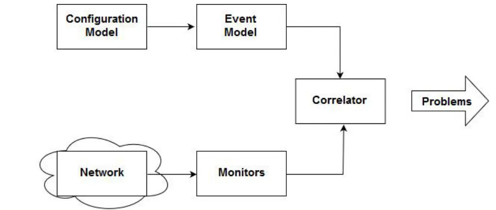
Fig. shows codebook correlation. Monitors capture alarm events & input then to the correlator. The configuration model contains the configuration of the network.
The event model represents various events and their casual relationships. The correlator correlated the alarm events with the event model and determines the common problems that caused the alarm event, In this approach, problem events are viewed as
messages generated by a system and encoded in sets of alarms that they cause. The function of correlator is to decode those problem messages to identify problems, this coding techniques comprised two phase
Q19) Discuss OAMP with respect to network management? (Dec 2018 5 M)
1. Operation, administration, maintenance and provisioning (OAM&P) functions form the cornerstones of managing a network 2. One of the best example of network management functional model is the OAM&P model
3. Operations: Involve the day to day and often minute to minute care and feeding of the data network in order to ensure that it is fulfilling its designed purposes. It also involves comparing measured performance against objective and taking corrective action and involving maintenance
4. Administration: Involves the set of activities involved with designing the network, processing orders, assignment address, tracking usage change management and accounting
5. Maintenance: Involves the inevitable circumstances that arise when everything does not work as planned or when it is necessary to diagnose what went wrong and repair it.
Q20) List & describe SNMP command with syntax? Dec 2018 (10 M)
Command Syntax Explanation
DISABLE SNMP disable snmp Enter this command to disable SNMP and all SNMP related commands. Be default, SNMP is disabled.
ENABLE SNMP enable snmp Enter this command to enable SNMP and all SNMP related commands. By default, SNMP is disabled. SET SNMP TRAPCOMMUNITY set snmp trapcommunity {<"Trap community string">}
Enter this command to set the trap community string. By default, the value is “COMPAQ”.
SET SNMP TRAPDEST
set snmp trapdest {,1 / 2 / 3 } {[none] / []}
Command Syntax Explanation
Specify none to remove a trap destination..
SHOW SNMP show snmp Enter this command to show all SNMP configuration settings.