EFFECT OF FLEXURAL AND MEMBRANE STIFFNESSES ON
THE ANALYSIS OF FLOATING ROOFS
S. Tariverdilo*
Department of Civil Engineering, Urmia University P.O. Box 165, Urmia, Iran
R. Shabani
Department of Mechanical Engineering, Urmia University P.O. Box165, Urmia, Iran
[email protected] - [email protected]
H. Salarieh
Department of Mechanical Engineering, Sharif University of Technology P.O. Box 11365-9567, Tehran, Iran
*Corresponding Author
(Received: January 21, 2009 – Accepted in Revised Form: November 5, 2009)
Abstract With the aim of extending the use of integrated variational principles on fluid and deck plate to the large deflection analysis of floating roofs, this paper investigates the significance of the flexural and membrane components in the formulations of the deck plate. Applying integrated variational principles on deck plate and fluid facilitate the treatment of the compatibility of deformation between floating roof and supporting liquid. Analysis results showed that different assumptions about deck plate formulation were commonly used in the literature which resulted in considerably different deflection and stress patterns on the floating roof. The results showed that modeling of the deck plate as a flexural element rather than membrane, by eliminating the need for nonlinear analysis, gave reasonable results for deflections and stresses in the deck plate. Finally, a simple and efficient procedure using linear finite element code analyzes of the floating roofs, considering only the flexural stiffness was developed.
Keywords Floating Roof, Variational Principle, Large Deflection
هﺪﻴﻜﭼ
ﻪﭼرﺎﭙﻜﻳمﺮﻓلﺎﻤﻋاﺎﺑوولﺎﻴﺳﻪﺑﻲﺷدرولﻮﺻازايا ﻞﻜﺷﺮﻴﻴﻐﺗﺰﻴﻟﺎﻧآياﺮﺑقر
ﻒﻘﺳگرﺰﺑيﺎﻫ
يﺎﻫ
ﻒﻘﺳﻦﻳارﺎﺘﻓرﻲﺳرﺮﺑردﻲﻳﺎﺸﻏوﻲﺸﻤﺧﻲﺘﺨﺳﺖﻴﻤﻫا ناﺰﻴﻣﻲﺳرﺮﺑدﺪﺻردﻪﻟﺎﻘﻣﻦﻳا،روﺎﻨﺷ ﻲﻣﺎﻫ
ﺪﺷﺎﺑ
.
زﺎﻴﻧﻪﻠﺌﺴﻣﻦﻳاﻲﺳرﺮﺑياﺮﺑﻲﺷدرولﻮﺻالﺎﻤﻋا ﻞﻜﺷﺮﻴﻴﻐﺗيرﺎﮔزﺎﺳلﺮﺘﻨﻛﻪﺑ
ﻲﻣفﺬﺣارلﺎﻴﺳوقروﻦﻴﺑﺎﻫ ﺪﻨﻛ
.
نﺎﺸﻧﺎﻫﺰﻴﻟﺎﻧآﺞﻳﺎﺘﻧ زاﻲﺗوﺎﻔﺘﻣﻼﻣﺎﻛﺞﻳﺎﺘﻧﻪﺑﺮﺠﻨﻣﻢﺘﺴﻴﺳﻦﻳاﺰﻴﻟﺎﻧآياﺮﺑﻒﻠﺘﺨﻣتﺎﻴﺿﺮﻓلﺎﻤﻋاﻪﻛﺖﺳانآﺮﮔ
ﻞﻜﺷﺮﻴﻴﻐﺗﻊﻳزﻮﺗﺮﻈﻧ ﺶﻨﺗوﺎﻫ
ﻲﻣﺎﻫ ددﺮﮔ
.
ﻲﻣنﺎﺸﻧﺞﻳﺎﺘﻧﻦﻴﻤﻫ هدﺎﻔﺘﺳاﺎﺑﻲﻌﻗاورﺎﺘﻓرزاﺐﻳﺮﻘﺗﻦﻳﺮﺘﻬﺑﻪﻛﺪﻫد
ﻲﻣﺖﺳﺪﺑﻲﺸﻤﺧﻲﺘﺨﺳزا
ﻧردوهﺪﺷﻲﻄﺧنﻮﻴﺳﻻﻮﻣﺮﻓﺖﻟﺎﺣﻦﻳاردﻪﻛﺪﻳآ
ﻢﻫيدﺪﻋﻞﺣتﻼﻜﺸﻣﻪﺠﻴﺘ
ﻪﺑ
ﻲﻣﺶﻫﺎﻛﻲﺳﺎﺳارﻮﻃ
ﺪﺑﺎﻳ
.
1. INTRODUCTION
Floating roofs are used in the petroleum industries for storage of liquid hydrocarbons in atmospheric storage tanks. By reducing the evaporation rate of stored materials, floating roofs provide better
environmental pollution caused by evaporation. The conventional floating roofs can be categorized into two types: single deck and double deck. The single deck floating roofs, which are the subject of this study, consist of a circular deck plate and a circumferential pontoon and in some cases a central pontoon. In these roofs in addition to the pontoon buoyancy, the buoyancy provided by the liquid under deck plate is also essential for the equilibrium of the system.
Due to the large deflection of the deck plates near the edges, it was anticipated that large deflection analysis would be important in the analysis of the deck plate. With this in mind, different researchers adopted different formulations for the deck plate in their analyses. Mitchell [2] investigated the stability of the pontoon in floating roofs. Ignoring the flexural deformation and applying large deflection formulation on the deck plate, he evaluated the forces exerted on the pontoon from the deck plate. Then, with the assumption of small displacements of pontoon, he investigated the possibility of in plane, out of plane and torsional buckling of the the pontoon due to the forces exerted on it by the deck plate. Epstein [3] used the shooting method with Runge-Kutta numerical integration technique to solve the boundary value problem of the deflection of a floating roof. He used a large deflection formulation ignoring the flexural stiffness of the deck plate. Yuan, et al [4] introduced a method based on an equivalent first order ordinary differential equation to solve the deflection and stress distribution in floating roofs with circumferential and central pontoons. They derived the equivalent formulation in the state space and then proposed a solution algorithm to solve the resulting first order ordinary differential equations. They used a large deflection formulationincluding flexural deformation. Nerantzaki, et al [5] developed a boundary element formulation to study the effect of the ponding of rainwater on floating roofs, modeled as a membrane. Sun, et al [6] after deriving the formulation of the load and deformation, proposed an iterative method to modify the buoyancy forces due to the supporting liquid and applied load due to rainwater accumulation on the top of the deck plate. Nagata, et al [7] and Ohmatsu [8] analyzed a rectangular large floating structure using a semi-analytical approach based on eigenfunction expansions in the depth direction. Seto, et al [9] developed a hybrid
element method (as a combination of the finite element method and infinite element) for hydroelastic analysis of a large floating structure in stepped-depth configuration. Iijima, et al [10] analyzed the hydroelastic behavior of semi-submersible type floating structures using their program named VODAC.
Variational principles greatly simplify treating the compatibility of deformation between the deck plate and the contained fluid. Isshiki, et al [11] by integrating Hamilton’s variational principle for plate and Kelvin’s principle for liquid derived the Hamilton-Kelvin principle. Then by introducing the velocity potential as an alternative variable instead of the fluid velocity, they developed different schemes of so-called Hamilton-Dirichlet’s principles. Nagata, et al [12] and Ohmatsu [13] successfully applied this variational formulation to analyze an elastic floating plate. Investigating the possible causes of sinking of the floating roofs during Niigata earthquake, Sakai, et al [14] used the variational principle to study the sloshing behavior of floating roofs. By considering only flexural stiffness, they developed a linear formulation to study the effect of presence of the floating roof on the sloshing behavior of the contained liquid during earthquakes.
As discussed above, different researcheres adopted different hypotheses about the deck plate in their formulations. Some (e.g. Epstein [3]) ignoring the flexural stiffness of the deck plate used the large deflection formulation to develop their derivations, while some others (e.g. Nagata, et al [12]) to have a linear formulation ignored the deck plate membrane stiffness and developed their formulation by taking into account only the flexural stiffness. On the other hand, some other researchers (e.g. Yuan, et al) [4] considered the flexural and membrane stiffnesses altogether in their derivations.
ignoring the membrane stiffness results in good estimate for the deck plate deflections and stresses. By this way, it is possible to evaluate these deflections and stiffnesses using simple analyses employing commercial linear finite element codes.
2. THE VARIATIONAL PRINCIPLE
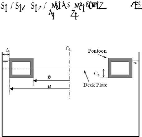
Floating roofs essentially consist of a circular deck plate and an outer circumferential pontoon as is shown in Figure 1. Applying variational principles simultaneously on the deck plate and the liquid facilitates the problem of imposing the compatibility of deformation between the floating roof and the supporting liquid. It also eliminates the need for two-phase analysis of the system as a coupled field. In the following derivations, two main assumptions are made. The first is that the supporting liquid and the floating roof are in full contact, which seems reasonable for a stationary liquid. The second is the assumption of rigid pontoon. This hypothesis is justified by the dimension of the pontoon being large in comparison with the deck plate.
Assuming that the plate and the fluid are always in contact with each other, the Lagrangian of the deck plate (Ld) and fluid (Lf) reduces to [11] the following equations:
d S
ghwdS d d
V UdV 2
d L 1 d L d
L (1a)
d S
dS 2 w 2
g f
L (1b)
Where U denotes the deck plate strain energy, Vd and Sd are deck plate volume and area (deck plate-fluid interface), ρ and ρd are fluid and deck plate density, h is deck plate thickness and w shows the plate deflection relative to the pontoon. Note that the plate Lagrangian includes the strain energy of the deck plate and its weight, and the fluid Lagrangian takes into account the buoyancy force exerted on the deck plate by fluid. Using the principle of virtual work and equating the variation of Ld and Lf to the variation of the work done by pontoon buoyancy force (Wp), we have:
p W ) f L d L
(
(2)
Variation of the strain energy component of the deck plate Lagrangian becomes:
dV ) r r
V rr rr
( 1 d
L
(3)
Considering the large deflection theory and assuming that the in plane displacements are infinitesimal and also ignoring the nonlinear terms in strain-displacement relation due to this in plane displacements (Von Karman theory), the strain-displacement relation is obtained [15]:
w . r w r 1 r u r u r u r 1 r
2 w r 1 2 1 rr u u r 1
2 ) r w ( 2 1 rr u rr
(4)
Where the displacements are as follow:
w r 1 z 0 u u
r w z 0 r u r u
(5)
Here u0
and u0r denotes the tangential and radial displacement in the neutral axes of the deck plate. Taking into account the axisymmetry of the Figure 1. Schematic diagram of a floating roof with
solution, (.)/0,u0 and the plate strain energy reduces to the following equation:
d . rdr ]} r w r w r 0 r u r 0 r u 2 ) r w ( 2 1 r w r w 2 ) r w ( 2 1 r w r w r 0 r u r 0 r u 2 ) r w ( 2 1 [ 2 1 Eh ] r 0 r u r 0 r u r 0 r u r 0 r u r 0 r u r 0 r u r 0 r u r 0 r u [ 2 1 Eh ] r w 2 r w 2 r 2 r w 2 r w r r w r w 2 r 1 2 r w 2 2 r w 2 d S [ ) 2 1 ( 12 3 Eh { 1 d L (6) Due to the large stiffness of the pontoon in
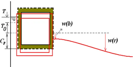
comparison with the deck plate and by ignoring any deformation in the pontoon, the assumption of rigid pontoon is used. To calculate the work done by the pontoon buoyancy, the increase in the height of the free surface should be calculated. The increase in the height of liquid free surface in a tank is different from that of open seas. The increase in the height of the liquid free surface is decomposed to the deflection due to pontoon (T0) plus the increase due to the deflection of the deck plate (T). Assuming incompressible liquid, the increase in the height of the liquid surface due to pontoon T0 (Figure 1) can be evaluated as follows:
] 2 a 2 ) a [( 0 T p C ) 2 b 2 a ( (7)
The increase in the height of the liquid free surface due to the deflection of the deck plate T regarding Figure 2 and noting that upward deflection in the plate is assumed as positive, is obtained:
Sf wdS ) b ( w ) 2 b 2 a ( ) 2 a 2 ) a ((
T (8)
For the definition of the parameters, see Figures 1 and 2. Now the buoyancy force of the pontoon Fp may be calculated as:
) 2 b 2 a ( g 0 )) b ( w p C 0 T T ( p
F (9)
Where ρ0 denotes ρ-ρp, and ρp denotes the pontoon density. Therefore, the variation of the work done by pontoon buoyancy is derived as follows:
w ) 2 b 2 a ( g 0 ) b ( w p C ) 2 a 2 ) a ( ) 2 b 2 a ( p C ) 2 a 2 ) a (( d S wdS ) b ( w ) 2 b 2 a ( w p F p W (10)
Now to apply an approximate Ritz solution, assume that w and ur are functions of known interpolation functions of fi and gi, then we have:
J 1 i ) r ( i g i c 0 r u ; I 1 i ) r ( i f i B w (11)
Where Bi and ci are the unknown coefficients. Substituting w from Equation 11 in Equation 10, the virtual work of the pontoon buoyancy force can be written as:
I 1 j ) b ( j f j B ) 2 b 2 a ( g 0 I 1
Substituting w and ur from Equation 11 in the plate strain energy and evaluating the variational equilibrium, we will have:
i Q I 1 l J 1 k k c l B lki I 1 l I 1 k I 1 m m B k B l B lkmi I 1 j I 1 l J 1 k k c l B lki j B ) ij gU ij Q ( (13a) 0 I 1 l I 1 k k B l B lki J 1 j I 1 l I 1 k k B l B lki j c ij
H
(13b) Where rdr b 0 ) r ( j f ) r ( i f 2 ij U b 0 dr ) r ( i f ) r ( k g ) r ( l f 2 1 2 Eh 2 lki b 0 rdr ) r ( i f ) r ( m f ) r ( k f ) r ( l f 2 1 Eh lkmi ) b ( i f F rdr b 0 ) r ( i f hg 2 i Q b 0 rdr ) r ( i f ) r ( k g ) r ( l f 2 1 Eh 2 lki dr ))] r ( j f ) r ( i f ) r ( j f ) r ( i f ( r ) r ( j f ) r ( i f 2 r 1 ) r ( j f ) r ( i f b 0 [ r ) 2 1 ( 12 3 Eh 2 ij Q p d (14) dr ))] r ( j g ) r ( i g ) r ( j g ) r ( i g ( r ) r ( j g ) r ( i g 2 r 1 b 0 ) r ( j g ) r ( i g [ r 2 1 Eh 2 ij H (15) b 0 rdr ) r ( i g ) r ( k f ) r ( l f 2 1 Eh
lki (16)
b 0 rdr ) r ( i g ) r ( k f ) r ( l f 1 Eh
lki (17)
With the assumed interpolation functions and by
solving the resulting set of nonlinear Equation 13, it is possible to calculate the deck plate deformation and stresses.
To satisfy the axisymmetric boundary conditions, the assumed approximation for w and ur should satisfy the following conditions:
0 0 r| ) r ( 0 r u ; 0 0 r| ) , r ( r ,
w (18)
and in terms of interpolation functions:
0 0 r| ) r ( i g ; 0 0 r| dri df
(19)
To satisfy these boundary conditions the following interpolation functions are used in this study:
b r n sin ) r ( n g ; b r n cos ) r ( n
f (20)
The resulting set of nonlinear equations are solved using the Newton-Raphson method. The convergence tolerance of an energy increment of 10-8 is used in the analyses.
3. SIMULATION RESULTS
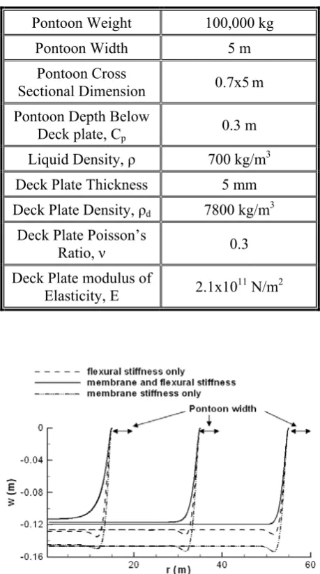
To assess the impact of different formulations on the global and local response of a typical floating roof, the deflection and stress distributions of the deck plate are calculated for formulations including membrane and flexural stiffnesses, flexural stiffness only, and finally membrane stiffness only. To obtain the results for the case of flexural stiffness only, the nonlinear terms in the strain equation (Equation 4) have been ignored and the results with membrane stiffness only is calculated by ignoring the second term on the right hand side of the displacement equation (Equation 5). Table 1 denotes the value of the parameters used in this study.
deflection, while disregarding the membrane stiffness corresponds to at most 18 % increase. Also, note that the deformation pattern near the pontoon for the deck plate in formulations ignoring flexural or membrane stiffnesses are slightly different from that of considering both stiffnesses. Figure 4 shows the stress on the bottom side of the deck plate for tanks of aforementioned diameters, calculated with different assumptions. Examining the total stress at the bottom face of the deck plate shows that in the case of flexural
stiffness, there are increases in negative and positive stresses by 6 and 83 %, nearly the same value for all tank diameters is considered in the study. In both cases, the maximum stress occurs at deck plate-pontoon connection and is mainly due to the flexural deformation, therefore, disregarding the membrane stiffness will have negligible effect on the design thickness of the deck plate. On the other hand, design of the deck plate by considering only the membrane stiffness, results in the elimination of flexural stresses at deck plate-pontoon connection and there is a significant change in the pattern of deflection and stress. In addition, there is a considerable decrease in the total stress, where the maximum stress is about 33 % of the case with both membrane and flexural stiffnesses for tank of 20 m in diameter, and this maximum stress tends to zero with increasing the tank diameter. Also, in this case, the noticeable increase of the membrane stresses for the 20 m diameter tank in comparison with the 40 and 60 m tanks is interesting.
The results show that different assumptions regarding the stiffness formulation of the deck plate give substantially different patterns of deflection and stress on the deck plate. Considering only membrane stresses in the stress analysis of the deck plate may be extremely unconservative and at the same time, it yields excessively large estimates of the actual deflection. On the other hand, reviewing Figures 3 and 4 shows that designing TABLE 1. The Data used in the Study.
Pontoon Weight 100,000 kg
Pontoon Width 5 m
Pontoon Cross
Sectional Dimension 0.7x5m Pontoon Depth Below
Deck plate, Cp 0.3 m Liquid Density, ρ 700 kg/m3 Deck Plate Thickness 5 mm Deck Plate Density, ρd 7800 kg/m3
Deck Plate Poisson’s
Ratio, ν 0.3
Deck Plate modulus of
Elasticity, E 2.1x10¹¹ N/m2
Figure 3. Comparison of the deck plate deflection using different formulations, for tanks of different diameters.
deck plate assuming only the flexural stress will be conservative for both stress and deflection evaluations. The linearity of the governing equations in this case also increases its attractiveness.
To develop an approximate solution to the problem, consider the governing equation for a floating plate ignoring the membrane stiffness:
wg g d t d w 4 ) 2 1 ( 12
3
Eh
(21)
This equation could be rewritten as follows:
g d t d wg w 4 ) 2 1 ( 12
3
Eh
(22)
This is the governing equation for plate on elastic foundation with stiffness of ρg and distributed load of ρdtdg. Considering this equation, the floating plate could be simply modeled as a plate on elastic foundation.
In this study, ABAQUS [16] is used as finite element code for analysis of the floating roof. To reduce the computational demand and at the same time to increase the accuracy of the analysis, an axisymmetric model of the structure is developed as depicted in Figure 5. To develop this axisymmetric model, at each node, local axes are considered parallel or perpendicular to the radial line connecting the node to the center of the floating plate. Then restraint in the nodes defined in such a way to synthesize the axisymmetric deformation. In the finite element model, the pontoon is modeled as natural extension of the deck plate, while to reflect its weight and stiffness, different values of the plate thickness in this area are used and the stiffness of the plate in pontoon area is increased. While the deck plate buoyancy has the value of ρgw, the pontoon buoyancy has the value of ρg(Cp+w), therefore it is not possible to model the buoyancy force for the deck plate and pontoon using the same springs. Here the buoyancy force in the deck plate area is modeled using springs with stiffness of ρg, and in the pontoon area, an upward pressure is applied as buoyancy force. The value of this upward pressure is evaluated using trail and error as is described in the following. First, a value for this pressure is considered which is slightly larger than the
distributed load corresponding to the weight of the pontoon. Then, the deflection at pontoon centerline is evaluated from the results of finite element analysis. Then, the corresponding buoyancy force for the measured deflection is evaluated. If the calculated buoyancy pressure is larger than the applied pressure, the pressure is increased, otherwise it is decreased. This process is repeated until the difference between the applied pressure and buoyancy pressure reduces to an acceptable value. In general, few iterations are required to obtain acceptable accuracy.
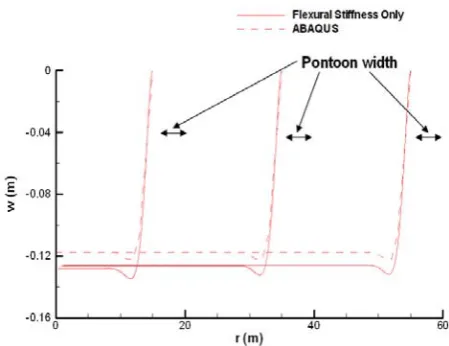
Figure 6 compares the deflection pattern calculated using variational formulation with those evaluated using ABAQUS. The deformation pattern is similar and the difference in the deflection for central part of the plate is mainly originated from the possibility of the rotation of the
Figure 5. ABAQUS axisymmetric finite element model of the floating roof.
pontoon in the ABAQUS model, while the variational formulation does not consider any rotation for pontoon. The pattern of flexural stress distribution for both cases is very similar with very small difference; therefore, it is not depicted here.
4. CONCLUSIONS
Applying the variational principle simultaneously on the deck plate and the supporting liquid, the large deflection formulation of the system composing of the floating roof and the liquid is derived. The integral equations of the system are derived employing the principle of virtual work. Simulation results show that different assumptions regarding the stiffness of the deck plate, results in significantly different patterns of stress and deflection in the floating roof. It is shown that the best possible simplification will be to use only the flexural stiffness for the deck plate, which results in a reasonable estimate of the stress and deflection in the deck plate. At the end, for analyzing the floating roof considering only flexural stiffness and employing finite element codes, a simple and efficient procedure is developed.
5. REFERENCES
1. Changa, J.I. and Linb, C.-C., “A Study of Storage Tank Accidents”, Journal of Loss Protection in the Process Industries, Vol. 19, No. 1, (2006), 51-59.
2. Mitchell, G.C., “Analysis and Stability of Floating
Roofs”, Journal of the Engineering Mechanics ASCE,
Vol. 99, No. 10, (1973), 1037-1052.
3. Epstein, H.I., “Stress and Displacements for Floating
Pan roofs”, Computers and Structures, Vol. 15, No. 4,
(1982), 433-438.
4. Yuan, S., Wang, J. and Zhong, H., “Analysis of Floating Roofs by ODE-Solver Method”, Journal of Engineering Mechanics ASCE, Vol. 124, No. 10, (1998), 1129-1134.
5. Nerantzaki, M.S., John, T. and Katsikadelis, J.T.,
“Ponding on Floating Membranes”, Engineering Analysis
with Boundary Elements, Vol. 27, (2003), 589-596.
6. Sun, X., Liu, Y., Wang, J. and Cen, Z., “Strength and
Buoyancy Analyses of Floating Roof with Continuous Beams and Dome Frames under Rainwater Loading”,
Journal of Pressure Vessel Technology ASME, Vol.
129, No. 1, (2007), 73-82.
7. Nagata, S., Yoshida, H., Fujita, T. and Isshiki, H., “The Analysis of Wave-Induced Response of an Elastic Floating Plate in a Sea with a Breakwater”, Proceedings of 8th International Offshore and Polar Engineering Conference, Montreal, Canada, Vol. I, (1998), 223–
230.
8. Ohmatsu, S., “Numerical Calculation of Hydroelastic
Behavior of Pontoon Type VLFS in Waves”, Proceedings of 17th International Conference on Offshore Mechanics and Arctic Engineering, Lisbon, Portugal, OMAE98-4333 (1998).
9. Seto, H. and Ochi, M., “A Hybrid Element Approach To
Hydroelastic Behavior of a Very Large Floating Structure in Regular Waves”, Hydroelasticity in Marine Technology, Kashiwagi, M., Koterayama, W. and
Ohkusu (Eds), RIAM, Kyushu University, Japan ,
(1998), 185–193.
10. Iijima, K., Yoshida, K., and Suzuki, H., “Hydroelastic Analysis of Semisubmersible Type VLFS Capable of
Detailed Structural Analysis”, Hydroelasticity in
Marine Technology, Kashiwagi, M., Koterayama, W.
and Ohkusu, M. (Eds), RIAM, Kyushu University, Japan , (1998), 211–218.
11. Isshiki, H. and Nagata, S., “Variational Principles Related to Motion of an Elastic Plate Floating on a WaterSurface”,
Proceeding of the Eleventh International Offshore and Polar Engineering Conference, Stavanger, Norway, (2001), 190-197.
12. Nagata, S., Yoshida H., Fujita T. and Isshiki H., “The Analysis of the Wave Induced Responses of an Elastic Floating Plate”, Proceeding of the 16th International Conference on Offshore Mechanics and Arctic Engineering, Vol. VI, (1997), 163-169.
13. Ohmatsu, S., “Numerical Calculation of Hydro-Elastic
Responses of Pontoon Type VLFS”, Journal of Society of Naval Architecture of Japan, Vol. 182, (1997),
329-340.
14. Sakai, F., Nishimura, M. and Ogawa, H., “Sloshing
Behavior of Floating-Roof Oil Storage Tanks”,
Computers and Structures, Vol. 19, No. 1-2, (1984),
183-192.
15. Amibili, M., “Nonlinear Vibration And Stability of
Shells and Plates”, Cambridge University Press, N.Y., New York, U.S.A., (2008).
16. Pawtucket, R.I., “ABAQUS/Standard user’s Manual.