143
Copyright © 2016. Vandana Publications. All Rights Reserved.
Volume-6, Issue-6, November-December 2016
International Journal of Engineering and Management Research
Page Number: 143-159
Seismic Behavior of Steel Buildings using Viscous Fluid Dampers by Non
Linear Time History Analysis
Pouya Azarsa1, Mahdi Hosseini2, Seyed Amin Ahmadi3, Prof. N.V. Ramana Rao4 1
M. Tech in Structural Engineering, Dept. of Civil Engineering, Jawaharlal Nehru Technological University Hyderabad (JNTUH), Hyderabad, Telengana, INDIA
2Ph.D. scholar student in Structural Engineering, Dept. of Civil Engineering, Jawaharlal Nehru Technological University Hyderabad (JNTUH), Hyderabad, Telengana , INDIA
3
Ph.D. scholar student in Computer Science and Engineering, Dept. of Computer Science and Engineering, Jawaharlal Nehru Technological University Hyderabad (JNTUH), Hyderabad, Telengana, INDIA
4Professor, Department of Civil Engineering, Jawaharlal Nehru Technological University Hyderabad (JNTUH), Hyderabad, Telengana, INDIA
ABSTRACT
The aim of the present work is to reduce seismic response of structures using passive vibration control system namely Fluid viscous dampers in SAP2000. The buildings with 4 floors are considered for the study and the structures are subjected to seismic excitations on steel Building with& without bracing and dampers. The reductions in seismic response were compared. The Bhuj 2001earthquake data is used as ground motion data for performing nonlinear time history analysis. The dampers are installed in the structures only in the exterior frames. In recent years considerable attention has been paid to research and development of structural control devices with particular emphasis on diminish of wind and seismic response of buildings. In order to control the vibration response of building during seismic events, energy absorbing passive damping devices are most commonly used for energy absorption. The present work deals in reducing the seismic response using fluid viscous dampers connected to Steel Bracing for 4 floors when subjected to a seismic excitation of Bhuj 2001 earthquake ground motion. It is considered a regular steel structure with 3 variants of confirmation: Normal Steel Building, Steel Building with ‘X’ Bracing and Steel Building with Dampers. Nonlinear time history analysis has been performed for structures and observed the reduction in seismic response. Parameters studied are roof displacements, storey drifts and base shears. SAP2000 software analysis engine is used as the software tool for the seismic analysis of the structure. Roof displacements decreased highly to an extent of 80% and 66% compared to normal steel building and building with X bracings respectively. The result analysis shows a reduction of 45-53% in base shear and 41-17% in storey drift for structures equipped with fluid viscous when compared to normal steel building and building with X bracings Respectively. It expresses that providing bracings with
damper in outer frame of structure is more efficient than structure with only dampers.
Keywords-- Nonlinear time history analysis, Bhuj ground motion data. Viscous fluid dampers, SAP2000 , Roof displacements, Storey drifts , Base shears ,Passive control systems.
I.
INTRODUCTION
In addition to the loads due to the effects of gravity, earthquake loading must be considered when designing structures located in seismically active areas. The philosophy in the conventional seismic design is that a structure is designed to resist the lateral loads corresponding to wind and small earthquakes by its elastic action only, and the structure is permitted to damage but not collapse while it is subjected to a lateral load associated with moderate or severe seismic events. As a consequence, plastic hinges in structures must be developed in order to dissipate the seismic energy when the structure is under strong shakings.
The design methods based on this philosophy are acceptable to account for the needs for both economic consideration and life safety. However, the development of the plastic hinges relies on the large deformation and high ductility of a structure. The more ductility a structure sustains, the more damage it suffers.
144
Copyright © 2016. Vandana Publications. All Rights Reserved.
structure. These systems may take the form of seismic isolation systems or supplemental energy dissipation devices. An examination of the behavior and effects of these systems may begin with the consideration of the distribution of energy within a structure. During a seismic event, a finite quantity of energy is input into a structure. This input energy is transformed into both kinetic and potential (strain) energy which must be either absorbed or dissipated through heat. The structural performance can be improved if a portion of the input energy can be absorbed, not by the structure itself, but by some type of supplemental device. This is made clear by considering the conservation of energy relationship (Uang and Bertero, 1988):
E = Ek+ Es+ Eh + Ed
Where E is the absolute energy input from the earthquake motion, Ek is the absolute kinetic energy, Es is the recoverable elastic strain energy, Eh is the irrecoverable energy dissipated by the structural system through inelastic or other forms of action, and Ed is the energy dissipated by supplemental damping devices. The absolute energy input E, represents the work done by the total base shear force at the foundation on the ground (foundation) displacement. It, thus, contains the effect of the inertia forces of the structure.
Modern seismic isolation systems incorporate energy dissipating mechanisms. Examples are high damping elastomeric bearings, lead plugs in elastomeric bearings, mild steel dampers, fluid viscous dampers, and friction in sliding bearings. Another approach to improving earthquake response performance and damage control is that of supplemental energy dissipation systems. In these systems, mechanical devices are incorporated into the frame of the structure and dissipate energy throughout the height of the structure.
EARTHQUAKE PROTECTION SYSTEMS
The conventional approach to earthquake resistant design of buildings depends upon providing the building with strength, stiffness and inelastic deformation capacity which are great enough to withstand a given level of earthquake - generated force. This is generally accomplished through the selection of appropriate structural configuration and the careful detailing of the structural members such as beams and columns and the connections between them.
In the last two decades, special protective systems have been developed to enhance safety and reduce damage of structures during earthquakes. These alternative approaches aim to control the structural seismic response and energy dissipation demand on the structural members by modifying the dynamic properties of the system. Structural design approach using seismic response control is now widely accepted and frequently applied in Civil Engineering. In recent years, much attention has been paid to the research and development of structural control techniques such as active control system, passive control
system, semi active and Hybrid control system giving special importance on improvement of wind and seismic responses of buildings and bridges.
ACTIVE CONTROL SYSTEM
Active control is a relatively upcoming subfield of structural engineering. It assures improved response to passive systems at the cost of energy and more complex systems.
Active control system has been as any control system in which an external power source is required to provide additional forces to the structure in a prescribed manner, by the use of actuators.
The performance of active control is quite pronounced in some cases.
Most significant advantage of active control method is diminishes by their heavy reliance on external power supplies. The placement of sensors and the design of feedback schemes are also beyond the scope of most practicing engineers, and poorly designed active system may lead to deleterious energy inputs and destabilization of the primary system.
PASSIVE CONTROL SYSTEM
The most mechanically simple set of control schemes is enclosed in the passive control category, which has been widely accepted for civil engineering application.Housner et al. have both provided brief overviews on structural control, including proper definitions for the various types of control practically implemented in structures. According to them a passive control system is one that does not require an external power source. All forces imposed by passive control devices develop as direct responses to the motion of the structure. Hence, sum of the energy of both the device and the primary system will be constant.
The main purpose of these systems is to efficiently dissipate vibrational energy, and the various methods of achieving this can be categorized in two ways. The first method includes converting kinetic energy directly to heat, such as through the yielding of metals, the deformation of visco-elastic solids and fluids, or the implementation of friction sliders. The second method works on transferring energy among two or more of the vibrational modes of the building, generally achieved by adding a supplemental oscillator that absorbs the vibrations of the primary structures. Tune mass damper, tune liquid damper, base isolation are example of passive system.
SEMI-ACTIVE CONTROL
Semi-active control relies on the reactive forces that develop due to variable stiffness or damping devices rather than application of actuator forces.
The best advantage of semi-active systems is their ability to provide improved control forces with a low demand for power.
Hybrid system
145
Copyright © 2016. Vandana Publications. All Rights Reserved.
isolated structure which is equipped with actuator which actively controls the enhancement of its performance.
DAMPERS IN STRUCTURES
Passive energy dissipation technique is one of the widely adopted concepts to absorb earthquake energy without causing significant damages to the main structural elements. Passive energy dissipation devices are generally simple; easy-to- rehabilitate, economical and do not rely on external power, which could be a major concern during an earthquake.
Passive energy dissipation systems encompass a range of materials and devices for enhancing damping, stiffness and strength and can be used both for natural hazard mitigation and for rehabilitation of aging or deficient structures. In general, such systems are characterized by a capability to enhance energy dissipation in structural systems in which they are installed. The effect may be achieved either by conversion of kinetic energy to heat energy or by transferring of energy among vibrating modes. The first method includes devices that operate on principles such as frictional sliding, yielding of metals, phase transformation in metals, deformation of visco-elastic solids or fluids and fluid orificing. The latter method includes supplemental oscillators that act as dynamic absorbers.
In the last two decades, special protective systems have been developed to enhance safety and reduce damage of structures during earthquakes. These alternative approaches aim to control the structural seismic response and energy dissipation demand on the structural members by modifying the dynamic properties of the system. Currently, the most practical and reliable method of reducing seismic structural response is the use of passive response control systems. They can be classified according to the approaches employed to manage the input earthquake energy as (1) seismic isolation systems and, (2) passive energy dissipation systems.
DAMPING FORCE
The process through which free vibration diminishes is called damping. In damping the energy of the vibrating system is dissipated by various mechanisms. The damping is an inherent property of the system. Damping essentially causes energy loss in the system. The damping in actual structures is usually represented in a highly idealized manner. The damping coefficient is selected so that the Vibration energy it dissipates is equivalent to the energy dissipated in all the damping mechanisms, combined, present in the actual structure. This damping his idealization is therefore called equivalent viscous damping. the damping force Fd is related to the velocity u‟ across the linear viscous damper by .Where, The constant „C‟ is the viscous damping coefficient. Unlike the stiffness of a structure, the damping coefficient cannot be calculated from the dimensions of the structure and sizes of the structural elements. Damping ratio is ζ actually the measure of the damping in the structure given by ζ=C/2mωWhere,ωis
the fundamental natural frequency of the system. “ζ” is a quantity which has to be determined experimentally. It can be determined with the help of free vibration tests and also forced vibration systems. For ground acceleration data the damping ratio £ can be determined from ζ= ln Where
and are the extremes of the ground acceleration data
& J=Difference in The Time Steps at the Instants of Extremes. Generally non-linearity in damping is not considered even in non-linear analysis. For all practical purposes the damping ratios of the following materials are given below
Table 1:Damping ratios of different materials
As long as building made from one material we can incorporate the damping ratio.
DAMPERS
Damping is one of many different methods that have been proposed for allowing a structure to achieve optimal performance when it is subjected to seismic, wind storm, blast or other types of transient shock and vibration disturbances. Conventional approach would dictate that the structure must inherently attenuate or dissipate the effects of transient inputs through a combination of strength, flexibility and deformability. The level of damping in a conventional elastic structure is very low. During strong motions such as earthquakes conventional structures usually deform well beyond their elastic limits and eventually fail or collapse. Therefore, most of the energy dissipated is absorbed by the structure itself through localized damage as it fails.
Dampers can be installed in the structural frame of a building to absorb some of the energy going into the building from the shaking ground during an earthquake. The dampers reduce the energy available for shaking the building. This means that the building deforms less, so the chance of damage is reduced.
The concept of supplemental dampers added to a structure assumes that major of the input energy to the structure will be absorbed not by the structure itself, but rather by supplemental damping elements. An idealized damper would of a form such that the force being produced by the damper is of such a magnitude and function that the damper forces do not increase overall stress in the structure.
146
Copyright © 2016. Vandana Publications. All Rights Reserved.
liquid dampers, both of which are primarily applicable to wind vibration control, recentering dampers, and phase transformation dampers. In addition, there is a class of dampers, known as semi active dampers, which may be regarded as controllable passive devices in the sense that they passively resist the relative motion between their ends but have controllable mechanical properties. Examples of such dampers include variable-orifice dampers, magneto rheological dampers, and electro rheological dampers.
VISCOUS FLUID DAMPERS
Fluid viscous dampers were initially used in the military and aerospace industry. They were adapted for use in structural engineering in the late 1980‟s and early 1990‟s (Makris and Constantinou, 1990, Constantinou and Symans, 1992). Fluid viscous dampers typically consist of a piston head with orifices contained in a cylinder filled with a highly viscous fluid, usually a compound of silicone or a similar type of oil. Energy is dissipated in the damper by fluid orificing when the piston head moves through the fluid (Hanson and Soong, 2001). The fluid in the cylinder is nearly incompressible, and when the damper is subjected to a compressive force, the fluid volume inside the cylinder is decreased as a result of the piston rod area movement. A decrease in volume results in a restoring force. This force is undesirable and is usually prevented by using a run-through rod that enters the damper, is connected to the piston head, and then passes out the other end of the damper. Another method for preventing the restoring force is to use an accumulator (Symans and Constantinou, 1998). An accumulator works by collecting the volume of fluid that is displaced by the piston rod and storing it in the make-up area. As the rod retreats, a vacuum that has been created will draw the fluid out. A damper with an accumulator is illustrated in .
Experimental and analytical studies of buildings and bridges with fluid dampers is done & manufactured by Taylor devices Inc. The Taylor's device which has been filled with silicone oil consists of a stainless steel piston with a bronze orifice head and an accumulator. The flow through the orifice is compensated by a passive bimetallic thermostat that allows the operation of device over a temperature range of -40 to 700c. The force in the damper is generated by a pressure difference across the piston head. The fluid volume is reduced by the product of travel distance and piston rod area. Since the fluid is compressible, the reduction in volume causes a restoring
force which is prevented by accumulator.
The dampers in the experiments were constructed so that temperature of the fluid did not influence the results. To achieve this, the dampers were designed so that the temperature inside the device remained between –40C and 70C. This relatively wide range of temperature is where the mechanicalproperties were determined to be stable. The dampers in the study were subjected to steady-state harmonic motion at frequencies of 1, 2, and 4 Hz. Procedures have been developed through years for the seismic design of buildings equipped with fluid viscous dampers. The NEHRP (National Earthquake Hazards Reduction Program) and other codes give a trial-and-error approach for identifying the mechanical characteristics of additional damping devices. A simple procedure for the determination of damping coefficient isC= 2mxw (2)Equation (2) is used to find out the damping coefficient. In (2), m is the total floor mass is to be calculated by knowing the different dead loads acting on the structure, ξ is the damping coefficient and ω is the natural frequency of the structure. Modal analysis of the finite element model is done using SAP2000. From the modal analysis the time period T, is obtained. The natural frequency, ω of the structure can be calculate using,w =2p/T (3)Knowing the value of ω and assuming a suitable value of damping ratio ξ, the damping coefficient is to be determined using (2). This value of damping coefficient C is used in the analysis of the structure in SAP2000.From the different dynamic responses values of ξ and α are fixed as 0.2 and 0.5 respectively.
ABOUT SAP2000 ADVANCE FEATURES
SAP200 offers the widest assortment of analysis and design tools available for the structural engineer working on building structures. The following list represents advance and enhanced features of SAP2000 V 16:
User interface
Default templates for quick Starting
Grid System
Structural components such as joints, frames, cables, tendons, shell, solids, links, hinges, spring, etc.
147
Copyright © 2016. Vandana Publications. All Rights Reserved.
Design of Steel, Concrete, Aluminium and coldformed frames.
Quick & advance reporting.
NEED FOR PRESENT STUDY
• All structures are subjected to vibration. Recent destructive earthquakes in Bhuj have shown how vulnerable our structures and societies remain to natural phenomena. The enormous losses inflicted by such earthquake have motivated ever more stringent requirements on the performance of structural systems, in reducing of seismic effect on structure. The cost and performance requirements for both buildings and equipment have motivated advances in the field of Structural Control, which deals with methodologies for the protection of high performance structural systems. The Fluid viscous Damper is a device that is designed to effectively isolate such structures from harmful vibrations.
• Use of fluid viscous dampers to dissipate the earthquake energy so they reduces roof displacements, story drifts and base shear.
AIMS AND OBJECTIVES OF THE STUDY
To Study the seismic behavior of structures with 4 floor buildings with and without bracings using non linear time history analysis.
To illustrate the effects of Fluid Viscous dampers with varying floor levels by using non linear time history analysis.
SCOPE OF WORK
Application of Fluid viscous dampers in the structure using SAP2000 for four story structures and discussing the varying effects as to reduce the base shear, storey drifts and roof displacements in structural compared to buildings with and without bracings and economically safe way.
II.
METHODOLOGY
TIME HISTORY ANALYSIS
Time history analysis is a step by step procedure of the dynamic response of the structure to a specified loading that may vary with time. The analysis may be linear or non linear. Time history analysis is used to determine the dynamic response to a structure subjected to arbitrary loading. The dynamic equilibrium equations to be solved are given by
+ +
Where M is the diagonal mass matrix, C is the damping matrix and K is the stiffness matrix and r(t) is the applied load, , , are the displacements, velocities and accelerations of the structure. If the load includes ground accelerations, the displacements, velocities and accelerations are relative to this ground motion.
There are several options that determine the type of time history case to be performed:
• Linear vs. Non linear.
• Modal vs. Direct-integration
• Transient vs. periodic
INITIAL CONDITIONS
The initial conditions that describe the state of structure at the beginning of time history case.
These include
• Displacements and velocities
• Internal forces and stresses
• Internal state variables for non linear elements
• Energy values for the structure
• External loads
The accelerations are not considered initial conditions, but are computed from the equilibrium equation. For linear transient analyses, zero initial conditions are always assumed. For periodic analyses, the program automatically adjusts the initial conditions at the start of the analysis to be equal to the conditions at the end of the analysis.
MODAL TIME HISTORY ANALYSIS
Modal superposition provides a highly efficient and accurate procedure for performing time-history analysis.
To determine if the Modes calculated by the program are adequate to represent the time history response to the applied load, these things should be checked.
That enough Modes have been computed
That the Modes cover an adequate frequency range
That the dynamic load (mass) participation mass ratios are adequate for the
Load Patterns and/or Acceleration Loads being applied.
That the modes shapes adequately represent all desired deformations.
MODELING OF BUILDING USING TIME HISTORY ANALYSIS IN SAP2000
Collecting of Earth Quake data (BHUJ).
Defining Time History Function
Import the data of ground accelerations.
Display graph
Defining time history case.
Following are the general sequence of steps involved in performing nonlinear time history analysis using SAP2000 in the present study:
148
Copyright © 2016. Vandana Publications. All Rights Reserved.
cross sections, reinforcement details and materials used. Columns at the end of foundation can be modeled by considering the degree of fixity provided by the foundation. All the beam column joints are considered as rigid.
UPLOAD ACCELEROGRAMS TO SAP2000
Define the accelerogram in SAP2000
An accelerogram is basically the time-history of the acceleration experienced by the ground in a given direction during a seismic event
We need to input the accelerogram as a generic function defined in SAP2000 starting from a TXT file
Once the mechanical model of the structural system under investigation has been created, SELECT from the menu bar:
DEFINE -> FUNCTIONS -> TIME HISTORIES.
Define the accelerogram in SAP2000 - The accelerogram must be uploaded to SAP2000 as FUNCTION FROM FILE an option which can be selected from the drop-down list
Define the accelerogram in SAP2000. We can select:
o Name of the function (e.g. Bhuj earthquake)
o Location of the file by using the button BROWSE.
o Number of lines to skip (0 for Bhuj database)
o Number of points per line (0 for Bhuj database)
STEP BY STEP PROCESS TO PERFORM THE NON-LINEAR MODAL TIME HISTORY ANALYSIS
1. Define the ground acceleration numerically at every
time step
2. Define the structural properties.
a. Determine the mass matrix m and lateral stiffness matrix k
b. Estimate the modal dumping ratios
Determine the natural frequencies and natural modes of vibration
3. Determine the modal components of the effective earthquake force distribution.
4. Compute the response contribution of the nth mode by the following steps, which are repeated for all modes. 5. Perform static analysis of the building subjected to lateral forces to determine , the modal static response for each desired response quantity r.
6. Determine the pseudo –acceleration response of the nth mode SDOF system using numerical step methods. 7. Determine (t) using summation rule given in equation to get the final response.
NON LINEAR MODAL TIME HISTORY ANALYSIS IN SAP 2000
Following are the general sequence of steps involved in performing NLTHA using SAP2000 in the present study:
1. A two or three dimensional model that represents the overall structural behavior created.
2. For reinforced concrete elements the appropriate reinforcement is provided for the cross sections.
3. Frame hinge properties are defined and assigned to the frame elements.
4. Gravity loads composed of dead loads and a specified proportion of live load is assigned as seismic weight to the structure.
5. Free vibration un-damped modal analysis is performed to make note of the frequencies and time periods of the structure.
6. The time history function from a file is selected and the time history function is defined.
7. Non-linear link elements are included in the structure like isolators and dampers.
8. The non-linear modal time history load cases are defined by assigning the ground acceleration time history function as loading in X and Y directions. and by assigning proportional damping
9. NLTHA is set to run.
10. After the completion of the analysis the displacement pattern of the structure is studied and inter story drifts are calculated.
11. The other responses such as base shear, member forces, and response spectrum curves are noted.
III.
RESULT AND DISCUSSION
The aim of the present work is to reduce seismic response of structures using passive vibration control system namely Fluid viscous dampers in SAP2000. The buildings with 4floor are considered for the study and the structures are subjected to seismic excitations on steel Building with& without bracing and dampers. The reductions in seismic response were compared. The Bhuj 2001earthquake data is used as ground motion data for performing nonlinear time history analysis. The dampers are installed in the structures only in the exterior frames.
STRUCTURAL SPECIFICATIONS
Analytical investigations were carried out using SAP2000.
DETAILS OF FOUR STORIED BUILDING:
MATERIAL PROPERTIES: GEOMETRY:
Foundation Depth = 1.5m Each storey height = 3 m
Plan dimensions = 4.5 mx4.5 m for each bay No. of Bays = 6
149
Copyright © 2016. Vandana Publications. All Rights Reserved.
Table 2 : Structural specifications of buildings.
150
Copyright © 2016. Vandana Publications. All Rights Reserved.
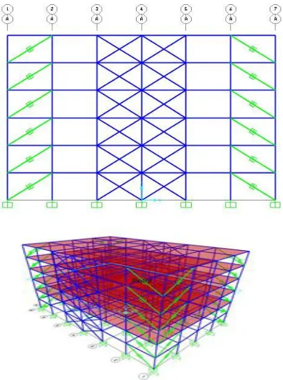
Figure 1: Plan view of the building
Figure 2: Position of bracings and dampers in the building
151
Copyright © 2016. Vandana Publications. All Rights Reserved.
Figure 5:Elevation view with damp
Figurer 4: Elevation view with X Bracings
LOADING
GRAVITY LOADING
Dead load of the structure will automatically calculated by the software itself based on the sizes and properties assigned. The slab is assumed to be of 125mm thick and exterior walls are of 230mm thick and interior walls are of 115mm thick The live load of 3kN/m2 is considered for entire floor and floor finishes of 1.5kN/m2 is applied as super imposed dead load.
NON-LINEAR MODAL TIME HISTORY ANALYSIS IN SAP 2000
Following are the general sequence of steps involved in performing NLTHA usingSAP2000 in the present study: Figure 4.1 shows acceleration time history of Bhuj Earthquake of January 26, 2001 at 08:46:42.9 I.S.T Mag: 7.0 mb, 7.6 Ms
Lat& Long: 23 02 N, 72 38 E Comp: N 12 W
Accelerogram Band pass filtered between 0.07 Hz and 27.0 Hz
Initial Velocity= -.1181E-02 m/s Initial Displacement = -1.006 mm
Peak Acceleration = -0.78236m/s/s at 34.945 sec. 26706 Acceleration data points (in m/s/s) at .005 sec
The time history loading is applied from earthquake data functions. Bhuj is a place located in the state of Gujarat which is a high intensity earthquake zone
of zone factor 0.36 which comes under the Zone-V according to the classification of seismic zones by IS 1893-2002 part-1.The records are defined for the acceleration points with respect to a time-interval of 0.005 second. The acceleration record has units of m/ and has a total number of 26,706 acceleration data.
Figure 6: Acceleration Vs Time graph for a Bhuj ground motion data
DAMPER MODELING
152
Copyright © 2016. Vandana Publications. All Rights Reserved.
Figure 7: Defining Link properties
The damper properties has draw to the structure using DRAW 2 JOINT LINK and assigning property DAMP1 to selected bracings in SAP2000.
ANALYSIS CASE
Nonlinear Time History case by using the BHUJ function applied in gravity direction by defining the
number of output steps are 26,706 and minimum step size is 0.005sec.
153
Copyright © 2016. Vandana Publications. All Rights Reserved.
ROOF DISPLACEMENTSFigure 9 : Roof displacement Vs Time for a four storied structure in X direction
Figure 10 :Roof displacement Vs Time for a four storied structure in Y direction
The maximum and minimum roof displacement for a four storied structure are 108.4mm, 99.2mm and 84.7mm, 90.08mm in X and Y directions respectively.
Figure11:Roof displacement Vs Time for a four storied structure in X direction with „X‟ bracings
Figure12 : Roof displacement Vs Time for a four storied structure in Y direction with „X‟ bracings
154
Copyright © 2016. Vandana Publications. All Rights Reserved.
Figure 13: Roof displacement Vs Time for a four storied structure in X direction with dampers
Figure 14: Roof displacement Vs Time for a four storied
structure in Y direction with dampers
The maximum and minimum of roof displacement for a four storied structure with dampers are 16.26mm, -19.65mm and 14.98mm, -13.08mm in X and Y directions respectively.
BASE SHEARS
Figure 15: Base shear Vs Time for a four storied structure in X direction
The maximum and minimum base shears of a four storied structure are 1641 kN and 1775kN @ 43.63sec and 43.05 seconds in X directions respectively.
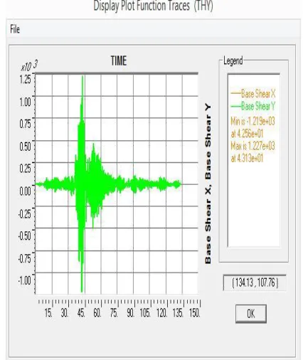
Figure 16: Base shear Vs Time for a four storied structure in Y direction
155
Copyright © 2016. Vandana Publications. All Rights Reserved.
Figure17:Base shear Vs Time for a four storied structure in X direction with „X‟ Bracings
The maximum and minimum base shears of a four storied structure are 1938KN and -1779kN @ 43.14sec and 43.5 seconds in X directions respectively.
Figureure18: Base shear Vs Time for a four storied structure in Y direction with „X‟ bracings
The maximum and minimum base shears of a four storied structure are 1110 kN and 1469kN @ 46.3sec and 43.53 seconds in Y directions respectively.
Figure 19: Base shear Vs Tim e for a four storied structure in X direction with dampers
The maximum and minimum base shears of a four storied structure are 889.4 kN and 821.8kN @ 42.5sec and 42.96 seconds in X directions respectively.
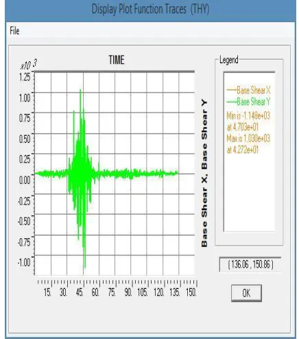
Figure 20: Base shear Vs Time for a four storied structure in Y direction with dampers
156
Copyright © 2016. Vandana Publications. All Rights Reserved.
Figure21:Base shear for four storied structures in X
direction Figure22: Base shear for four storied structures in Y direction
Figure 23:Roof Displacement for a four storied structure in X direction
157
Copyright © 2016. Vandana Publications. All Rights Reserved.
Figure25:Storey drift for a four storied structure in X direction
Figure26:Storey drift for a four storied structure in Y direction
According to results obtained, the discussions are presented as follows
DISCUSSION
PERFORMANCE ON NORMAL STEEL STRUCTURES (WITHOUT BRACING AND WITHOUT DAMPERS) UNDER NONLINEAR TIME HISTORY ANALYSIS. A) ROOF DISPLACEMENTS
The maximum and minimum roof displacements for a four storied structure are 108.4mm, 99.2mm and 84.7mm, 90.08mm in X and Y directions respectively.
B) STOREY DRIFTS
The maximum storey drift for a four storied structure in X & Y direction is 10.4mm, 10.3 mm respectively.
C) BASE SHEARS
The maximum and minimum base shears of a 4storied structure are 1641kN and 1775kN @ 43.63sec and 43.05 seconds in X directions respectively.
The maximum and minimum base shears of a four storied structure are 1219kN and 1227kN @ 42.53sec and 43.13 seconds in Y directions respectively
PERFORMANCE OF STRUCTURES WITH ‘X’ BRACINGS PROVIDED AT OUTER FRAME OF THE BUILDING
A) ROOF DISPLACEMENTS
The maximum and minimum of roof displacements for a four storied structure are 86.72mm, -86.62mm and 29.88mm, -39.63mmin X and Y directions respectively.
When the buildings are equipped with Bracing in Outer Frame of Structures, drastic reduction has taken place in roof displacements. The roof displacements decreased up to 64%, respectively for 4 storied buildings respectively.
B) STOREY DRIFTS
The maximum storey drift for a four storied structure in X & Y direction is 7.1mm, 7.7 mm respectively.
The buildings equipped with X bracings have shown a drastic reduction in storey drifts and the percentage reduction in storey drifts are found to be 32%, respectively for 4storied buildings respectively.
C) BASE SHEARS
The maximum and minimum base shears of a four storied structure are 1938kN and -1779kN @ 43.14sec and 43.5 seconds in X directions respectively.
The maximum and minimum base shears of a four storied structure are 1110 kN and 1469kN @ 46.3sec and 43.53 seconds in Y directions respectively
When the buildings are equipped with „X‟ Bracings in Outer Frame of Structure, the base shears increased by 16%, in 4storied buildings respectively.
PERFORMANCE OF STRUCTURES WITH FLUID VISCOUS
A) ROOF DISPLACEMENTS
The maximum and minimum of roof displacements for a four storied structure are 16.26mm, -19.65mm and 14.98mm, -13.08mm in X and Y directions respectively.
When the buildings are equipped with Fluid viscous damper in Outer Frame of Structures, drastic reduction has taken place in roof displacements. The roof displacements variation of 4 storied decreased up to 80%, when compare to normal steel building and 66%, when compare to buildings with X bracings respectively.
B) STOREY DRIFTS
The maximum storey drift for a four storied structure in X & Y direction is 6.1 mm, 5.9 mm respectively.
158
Copyright © 2016. Vandana Publications. All Rights Reserved.
building with and without bracings. thestorey drifts variation of 4 storied decreased up to 41%, when compare to normal steel building and 17%, when compare to buildings with X bracings respectively.
C) BASE SHEARS
The maximum and minimum base shears of a four storied structure are 889.4 kN and 821.8kN @ 42.5sec and 42.96 seconds in X directions respectively.
The maximum and minimum base shears of a four storied structure are 1148 kN and 1030kN @ 47.03sec and 42.7 seconds in Y directions respectively
When the buildings are equipped with Fluid viscous damper in Outer Frame of Structures, drastic reduction has taken place in base shears. The base shears variation of 4 storied decreased up to 45%, when compare to normal steel building and 53%, when compare to buildings with X bracings respectively.
SUMMARY
This chapter explains the results obtained in the work such as roof displacements, storey drifts and base shears and their associated graphs with parameters mentioned. Also discussions are presented explaining the parameters affecting the structure. The next chapter discusses the conclusions of the study.
IV.
CONCLUSIONS
The Fluid viscous damper were found to be excellent seismic control devices for controlling forced Responses such as base shear, roof displacements and storey drift for buildings with varying stories
o The base shears decreased up to 45% when compare to normal steel building and 53% when compare to buildings with X bracings.
o The roof displacements decreased up to 80% when compare to normal steel building and 66% when compare to buildings with X bracings.
o The storey drifts decreased up to 41% when compare to normal steel building and 17% when compare to buildings with X bracings.
Reduction in Base shear did not follow any trend with increase in number of floors when buildings are equipped with Fluid viscous damper,
For the damper building, the reduction in storey drift decreases with increase in number of floors.
Buildings with „X‟ bracings reduce roof displacement and storey drift, but there is much increase in base shear.
The buildings equipped with X bracings have shown a drastic reduction in storey drifts and the percentage reduction in storey drifts are found
to be 32%, respectively for 4 storied buildings respectively.
When the buildings are equipped with „X‟ Bracings in Outer Frame of Structure, the base shears increased by 16%, in 4storied buildings respectively.
It can also concluded that providing bracings with damper in outer frame of structure is more efficient than structure with only dampers
SCOPE FOR FURTHER WORK
The further studies can be done by changing the position of placement of dampers in the core of the building on asymmetry in elevation and plan. It can also be extent by replacing the shear wall with dampers in structure.
REFERENCES
[1] Anil K. Chopra and Rakesh K. Goel, “A modal pushover analysis procedure to estimate Seismic demands for buildings: Theory and preliminary evaluation” PEER Report 2001/03.
[2] Flavia S. Florea, "Behaviour of Seismic Resistant Eccentrically Braced Frames", Technical University of Civil Engineering, Bucharest, Romania, February 15, 2010. [3] FloreaFlavia- Simona and RosuLoredana Elena, "Enhanced Seismic Resistance of Steel Structures using Passive Energy Dissipation Devices", Technical University of Civil Engineering.
[4] G.S. Balakrishna and Jini Jacob, "Seismic Analysis of Building using Two Types of Passive Energy Dissipation Devices”, IOSR Journal of Mechanical and Civil Engineering (IOSR-JMCE), e-ISSN: 2278-1684, p-ISSN: 2320-334X, PP 13-19.
[5] Liya Mathew and C. Prabha, "Effect of Field Viscous Dampers in Multi-Storeyed Buildings”, International Journal of Research in Engineering and Technology (IMPACT: IJRET), Vol.2, Issue 9, Sep 2014.
[6] Loredana E. Rosu, Flavia S. Florea, Catalin C. Rosu "Efficiency of using viscous dampers for multi-storey steel structures subjected to seismic actions”, 11th
International Conference on Vibration problems, Technical University of Civil Engineering, Lisbon, Portugal, 9-12 September 2013. [7] M. Palermo, S. Silvestri, G. Gasparini, T. Trombetti, & L. Landi “Seismic Design of Moment Resisting Frame Structures Equipped With Viscous Dampers” Italy .
[8] Murat Diclelia and Anshu Mehta “Seismic performance of chevron braced steel frames with and without viscous fluid dampers as a function of ground motion and damper characteristics” Journal of Constructional Steel Research 63 (2007) 1102–1115.
[9] M.C. Constantinou, M.D. Symans “seismic response of structures With supplemental damping, State University of New York Department of Civil Engineering Buffalo, NY 14260.
159
Copyright © 2016. Vandana Publications. All Rights Reserved.
under seismic Loading” Fourth Asia-Pacific Conference on FRP in Structures (APFIS 2013).
[11] Nitendra G Mahajan and D B Raijiwala “seismic response control of a building Installed with passive dampers” International Journal of Advanced Engineering Technology E-ISSN 0976-3945
[12] Ras A, Boukhari B, Boumechra N and Hamdaoui K “Dissipative Capacity Analysis of Steel Buildings using Viscous Bracing Device” Civil Engineering Department, Faculty of Technology, University of Tlemcen, BP 230 Tlemcen (13000), Algeria.
[13] V. SadeghiBalkanlou, M. Reza BagerzadehKarimi, B. BagheriAzar and AlaeddinBehravesh “ Evaluating Effects of Viscous Dampers on optimizing Seismic Behavior of Structures”, Young Researches and Elite Club, Islamic Azad University, Tabriz Branch, Iran, October 2013. .[14] YuvrajBisht and SaraswatiSetia, "Seismic Behaviour of a Soft Storey Building with and without Viscous Dampers”, International Journal of Engineering Research and Applications (IJERA) ISSN: 2248-9622, Nation Conference on Advances in Engineering and Technology (AET-29th March 2014).
[15] Taylor Devices India Pvt. Ltd., Unit 533, Vipul Trade center, sector-48, Sohna road, Gurgaon, Haryana-122002. [16] IS 1893 (Part I): 2002, Indian Standard- Criteria for earthquake resistant design of structures, part 1 general provisions and buildings, Bureau of Indian Standards, New Delhi, June 2002.
[17] SAP2000 Integrated Software for Structural Analysis and Design software verification example 6 link – suny buffalo damper with linear velocity exponent.