Convective Heat Transfer Analysis in a Circular Tube with
Different Types of Internal Threads of Constant Pitch
Ronak Dipakkumar Gandhi
I. INTRODUCTION
There are numerous techniques to embellish the heat transfer, such as fins , dimples, additives, etc. A great deal of research effort has been devoted to developing apparatus and performing experiments to define the conditions under which an enhancement technique will improve heat transfer. Heat transfer enhancement technology has been widely applied to heat exchanger applications in refrigeration, automobile, process industries etc. The goal ofenhanced heat transfer is to encourage or accommodate high heat fluxes. This result in reductionofheat exchanger size, whichgenerallyleads to less capital cost. Another advantage is the reduction of temperature driving force, which reduces the entropy generation and increases the second law efficiency
[1]. The need to increase the thermal performance of heat exchangers, thereby effecting energy, material & cost savings have led to development & use of many techniques termed as Heat
transfer Augmentation. These techniques are also referred as Heat transfer Enhancement or Intensification. Augmentation techniques increase convective heat transfer by reducing the thermal resistance in a heat exchanger. Use of Heat transfer enhancement techniques lead to increase in heat transfer coefficient but at the cost of increase in pressure drop. So, while designing a heat exchanger using any of these techniques, analysis of heat transfer rate & pressure drop has tobe done.Apart fromthis, issues like long-termperformance & detailed economic analysis of heat exchanger has to be studied. To achieve high heat transfer rate in an existing or new heat exchanger while taking care of the increased pumping power, several techniques have been proposed in recent years.
Generally, heat transfer augmentation techniques are classified in three broad categories: active methods, passive method and compound method. A compound method is a hybrid method in which both active and passive methods are used in combination. The compound method involves complex design and hence has limited applications. Kumar et al.
[2] experimentally showed the investigation to augment the heat transferrate byenhancingthe heat transfer coefficient during the condensation of pure steam and R-134a over horizontal finned tubes. Spines were found to be more effective in the bottom side of the circular integral tube. Suresh Kumar at al.
[3] numerically studied the thermo hydraulic performance of twisted tape inserts in a large hydraulic diameter annulus. The thermo hydraulic performance in laminar flow with a twisted tape is better than the wire coil for the same helix angle and thickness ratio. M. Sozen and T.M. Kuzay
[4] study showed that the enhanced heat transfer in round tubes filled with rolled copper mesh at Reynolds number range of 5,000-19,000. With water as the energytransport fluid and the tube being subjected to uniform
ABSTRACT:
This work presents an experimental study on the mean Nusselt number, friction factor andthermal enhancement factor characteristics in a circular tube with different types of internal threads of 120 mm pitch under uniform wall heat flux boundary conditions. In the experiments, measured data are taken at Reynolds number in range of 7,000 to 14,000 with air as the test fluid. The experiments were conducted on circular tube with three different types of internal threads viz. acme, buttress and knuckle threads of constant pitch. The heat transfer and friction factor data obtained is compared with the data obtained from a plain circular tube under similar geometric and flow conditions. Thevariations of heat transfer and pressure loss in the form of Nusselt number (Nu) and friction factor (f) respectively is determined and depicted graphically. It is observed that at all Reynolds number, the Nusselt number and thermal performance increases for a circular tube with buttress threads as compared with a circular tube with acme and knuckle threads. These are because of increase in strength and intensity of vortices ejected from the buttress threads. Subsequently an empirical correlation is also formulated to match with experimental results with ± 8% and ± 9%, variation respectively for Nusselt number and friction factor.
heat flux, they reported up to ten fold increase in heat transfer coefficient with brazed porous inserts relative to plain tube at the expense of highly increased pressure drop. Golriz and Grace
[5] experimentally showed that the addition of an angled deflector to the fin region of circular membrane water– wall heat exchanger surfaces in circulating fluidized beds can lead to a significant increase in the local heat transfer. Wang and Sunden
[6] reported correlations for ethyl glycol and polybutene (Pr. No.10000-70000)., They also concluded by considering the overall enhancement ratio, twisted tape is effective for small Prandtl number fluids and wire coil is effective for high Prandtl number fluids. Q Liao and M.D. Xin
[7] carried out experiments to study the heat transfer and friction characteristics for water, ethylene glycol and ISOVG46 turbine oil flowing inside four tubes with three dimensional internal extended surfaces and copper continuous or segmented twisted tape inserts within Prandtl number range from 5.5 to 590 and Reynolds numbers from 80 to 50,000. They found that for laminar flow of VG46 turbine oil, the average Stanton number could be enhanced up to 5.8 times with friction factor increase of 6.5 fold compared to plain tube. Chang et al. [8] experimentally showed that, in a duct fitted with transverse ribs, the flow cells behind the 908 ribs are no longer stagnant but periodically shed when the duct reciprocates. The typical zigzag stream-wise heat transfer variation along the ribbed wall in a stationary system yields a large wavy pattern in the reciprocating duct.
D. Angirasa [9] proved through experimental study which shows augmentation of heat transfer by using metallic fibrous materials with two different porosities namely 97% and 93%. The experiments were carried out for different Reynolds numbers (17,000-29,000) and power inputs (3.7 and 9.2 W). The improvement in the average Nusselt number was about 3-6 times in comparison with the case when no porous material was used. Fu et al. [10] experimentally demonstrated that a channel filled with high conductivity porous material subjected to oscillating flow is a new and effective method of cooling electronic devices. Afanasyev et al.
[11] studied different surfaces shaped by a system of spherical cavities in a turbulent flow and found that such shaping of the heating surface has no appreciable effect on the hydrodynamics of flow but results in considerable (up to 30–40 per cent) heat transfer enhancement. The experimental investigations of Hsieh and Liu
[12] reported that Nusselt numbers were between four and two times the bare values at low Re and high Re respectively. Bogdan and Abdulmajeed et al. numerically investigated the effect of metallic porous materials, inserted in a pipe, on the rate of heat transfer. The pipe was subjected to a constant and uniform heat flux. The effects of porosity, porous material diameter and thermal conductivity as well as Reynolds number on the heat transfer rate and pressure drop were investigated. The results were compared with the clear flow case where no porous material was used. The results obtained lead to the conclusion that higher heat transfer rates can be achieved using porous inserts at the expense of a reasonable pressure drop. Smith et. al.
[13] investigated the heat transfer enhancement and pressure loss by insertion of single twisted tape, full length dual and regularly spaced dual twisted tapes as swirl generators in round tube under axially uniform wall heat flux conditions. Chinaruk Thianpong et. al.
[14] experimentally investigated the friction and compound heat transfer behavior in dimpled tube fitted with twisted tape swirl generator for a fully developed flow for Reynolds number in the range of 12000 to 44000. Whitham
[15] studied heat transfer enhancement by means of a twisted tape insert way back at the end of the nineteenth century. Date and Singham
[16] numerically investigated heat transfer enhancement in laminar, viscous liquid flows in a tube with a uniform heat flux boundary condition. They idealized the flow conditions by assuming zero tape thickness, but the twist and fin effects of the twisted tape were included in their analysis. Saha et al.
[17] have shown that, for a constant heat flux boundary condition, regularly spaced twisted tape elements do not perform better than full-length twisted tape because the swirl breaks down in-between the spacing of a regularly twisted tape. Rao and Sastri
[19, 20] studied the thermo-hydraulic characteristics of tape-generated swirl flow. Peterson et al.
[21] experimented with high-pressure (8–16 MPa) water as the test liquid in turbulent flow with low heat fluxes and low wall–fluid temperature differences typical of a liquid–liquid heat exchanger.
The present experimental study investigates the increase in the heat transfer rate between a tubes heated with a constant uniform heat flux with air flowing inside it using internal threads of varying pitch. As per the available literature, the enhancement of heat transfer using internal threads in turbulent region is limited. So, the present work has been carried out with turbulent flow (Re number range of 7,000-14,000) as most of the flow problems in industrial heat exchangers involve turbulent flow region.
II.
EXPERIMENTAL WORK
2.1Experimental Setup
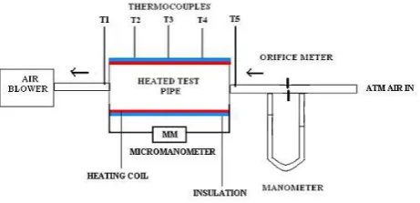
The apparatus consists of a centrifugal blower unit fitted with a circular tube, which is connected to the test section located in horizontal orientation. Nichrome bend heater encloses the test section to a length of 50 cm. Input to heater is given through dimmer stat. Three thermocouples T2, T3 and T4 at a distance of 11 cm, 22 cm, 33 cm and 44 cm from the origin of the heating zone are embedded on the walls of the tube and two thermocouples are placed in the air stream, one at the entrance (T1) and the other at the exit (T5) of the test section to measure the temperature of flowing air. The digital device is used to display the temperature measured by thermocouple at various position. The temperature measured by instrument is in 0C. The test tube of 110 mm thickness is used for experimentation. A micro- manometer measures the pressure drop across the test section, with double reservoir (range = 0.002–5 mbar) filled with benzyl alcohol and water. The pipe system consists of a valve, which controls the airflow rate through it and an orifice meter to find the volume flow rate of air through the system. The diameter of the orifice is 1.4 cm and coefficient of discharge is 0.64. The two pressure tapings of the orifice meter are connected to a water U-tube manometer to indicate the pressure difference between them. Display unit consists of voltmeter, ammeter and temperature indicator. The circuit is designed for a load voltage of 0-220 V; with a maximum current of 10 A. Difference in the levels of manometer fluid represents the variations in the flow rate of air. The velocity of airflow in the tube is measured with the help of orifice plate and the water manometer fitted on board.
2.2 Procedure
Air was made to flow though the test tube by means of blower motor. A heat input of 90 W was given to the nichrome heating wire wound on the test tube by adjusting the dimmer stat. The test tube was insulated in order to avoid the loss of heat energy to the surrounding. Thermocouples 2 to 4 were fixed on the test surface and thermocouples 1 and 5 were fixed inside the tube. The readings of the thermocouples were observed every 5 minutes until the steady state condition was achieved. Under steady state condition, the readings of all the five thermocouples were recorded. The experiments were repeated for four different test tubes with different types of internal threads viz. acme, buttress and knuckle threads of constant pitch with constant airflow rate. The fluid propertieswere calculated as the average between the inlet and the outlet bulk temperature. Experiments were carried out at constant heat input and constant mass flow rate, for all the four test tubes with different types of internal threads.
Fig.2: Photograph of Test tube with Internal Thread
2.3 Sequence of Operations
Experiments were carried out first on plain aluminum horizontal circular tube and then on aluminum horizontal circular tube with different types of internal threads viz. acme,buttress and knuckle threads of constant pitch.
2.3.1 Without internal threads: Initially, the experiment was carried out on plain circular tube without internal threads. The working fluid air flows through the tube section with least resistance.
2.3.2 With different types of Internal threads of constant pitch: The internal threads were done on tube as shown in Fig. 2. The three different test tubes with different types of internalthreads viz. acme, buttress and knuckle threads of constant pitch were used for experimentation. The presence of theinternal threads in the pipe causes resistance to flow and increases turbulence. The mass flow rates of air and the heat input were kept constant as that of plain tube experiment.
Data reduction
The data reduction of the measured results is summarized in the following procedures: Ts = ( T2 + T3 + T4)/3 - (Equation I )
Tb = ( T1 + T5 )/2 - (Equation II )
Discharge of air,
Q = Cd *A1 *A2 * (2ghair)/ (A12 – A22) - (Equation III )
Equivalent height of air column,
hair = ( w * hw ) / w
- (Equation IV )
Velocity of air flow,
V = (Q/A) - (Equation V) Where A =convective heat transfer area ( *D*L), Re = ( * V * D) / - (Equation VI) Where D = inner diameter of pipe
L= Length of pipe
Total Heat Transfer
Q = Qc + Qr - (Equation VII) Q = m Cp (T1 – T5)
- (Equation VIII) Where m= mass flow of air
Qc = Convective Heat Transfer Qr = Radiation Heat Transfer
Qr = A (Ts4 - Tb 4) - (Equation IX) h= (Q-Qr) / (A (Ts - Tb) - (Equation X)
Experimental Nusselt number
Nu = h* (D/ K) - (Equation XI)
Nusselt numbers calculated from the experimental data for plain tube were compared with the correlation
recommended by Dittus-Boelter.
Nu = 0.023 Re 0.8 Pr 0.4
In straight pipe lengths, Pressure drop ( using the Darcy Equation
f = Darcy friction factor
Friction factor correlation Correlation of Petukhov f = (0.790 ln Re – 1.64) –2 for 3000 Re 5 X 10⁶
- (Equation XIII)
The enhancement efficiency (ψ) is defined as the ratio of the heat transfer coefficient for the tube with internal threads (hc) to that for the plain tube without internal threads (hp) at a constant Reynolds number (CR) as follows (Yakut et al,2004):
h
c /h
p - (Equation XIV)III. RESULTS AND DISCUSSION
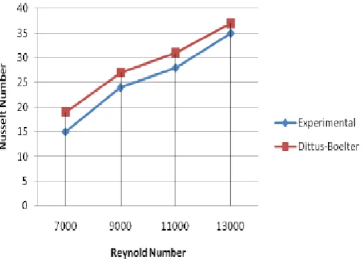
Experimentally determined Nusselt number values for plain horizontal circular tube (without internal threads) are compared with Dittus-Boelter correlation.
Fig. 3 shows the comparison between Nusselt numbers obtained experimentally and by using Dittus-Boelter
equation for plain tube. It is observed that the value of Nu (experimental) is less than Nu (Dittus-Boelter).
Actual heat carried away by air passing through the test section is the combination of convective and radiative
heat transfers. As the heat transferred by convection alone is considered while performing experimental and
numerical calculations, it can be expected that Nu (experimental) is less than Nu (Dittus-Boelter).
Fig. 3 Comparison between Nusselt numbers obtained experimentally, analytically by using Dittus-Boelter
Fig. 4 shows the variation of friction factor with Reynolds number for plain tube. The data obtained by the
experiment is compared with Petukhov equation XIII with the deviation of ± 9% for the friction factor.
Fig. 4 Validation of numerical results for friction factor of plain pipe against existing correlation
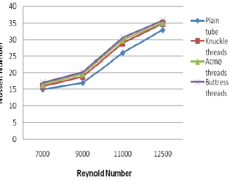
Fig.5showsthe variationofNusselt number withReynolds number in the plain tube and three different test tubes with different types of internal threads viz. acme, buttress and knuckle threads of constant pitch. It is observed that for all cases, Nusselt number increases with increasing Reynolds number. It is observed that for tube with internal threads the heat transfer rates are higher than those from the plain tube and also for a test tube with buttress threads the heat transfer rate is higher than those from test tubes with acme and knuckle threads. This is due to the fact that depth provided by the buttress threads is more as compared to acme and knuckle threads, which increases the strength and turbulent intensity of air across the range of Reynolds numbers. Mean Nusselt numbers for test tubes with internal threads such as buttress, acme and knuckle threads are respectively, 1.46, 1.30 and 1.19 times better than that for the plain tube.
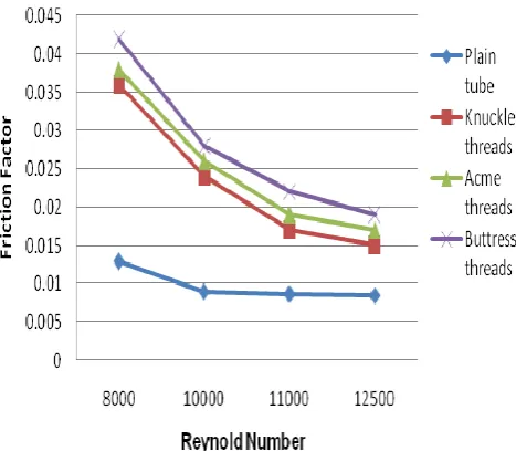
Fig.6 shows the variation of friction factor vs Reynolds number for the plain tube and three different test tubes with different types of internal threads viz. acme, buttress and knuckle threads of constant pitch. The friction factor for the test tube using internal threads is more than that for plain test tube. Also friction factor decreases with increase in Reynolds number for all the three different test tubes with different types of internal threads viz. acme, buttress and
Fig. 5 Variation of Nusselt Number Vs Reynolds Number for Plain tube and Tube with different threads type
compared to acme and knuckle threads, which increases the swirl flow of air across the range of Reynolds numbers.
Fig.6 shows thevariation offriction factor Vs Reynolds numberfor theplain tube and three different test tubes
Fig. 7 shows the variation of thermal enhancement factor with Reynolds number. At the same Reynolds number, the thermal enhancement factors for a test tube with buttress threads are found to be greater than those for the test tubes with acme and knuckle threads. The thermal enhancement factors for all the internal threads tend to decrease with increasing Reynolds number.
With the use of internal threads, the thermal enhancement factors are in a range between, 1.12 - 1.04, 1.1 -1.03 and 1.08 - 1.02 respectively for the test tubes with buttress, acme and knuckle threads.
IV. CONCLUSIONS
Experimental investigations of heat transfer, friction factor and thermal enhancement factor of a plain circular tube and a circular tube with three different types of internal threads viz. acme, buttress and knuckle threads of constant pitch are described in the present report. The conclusions can be drawn as follows:
1. The heat transfer enhancement increases for a test tube with buttress threads than those for test tubes with acme and knuckle threads. This is due to the fact that depth provided by the buttress threads is more as compared to acme and knuckle threads, which increases the turbulence of air.
2. The friction factor increases for a test tube with buttress threads than those for test tubes with acme and knuckle threads again due to more swirl flow exerted by the buttress threads.
3. The enhancement of Nusselt number is much higher than that of enhancement in friction factor for all the types of internal threads that justifies the usage of internal threads in horizontal tube.
4. The performance of circular tube can be improved by the use of internal threads. The cost involved for making internal threadsisminimal comparedtoenergyefficiency improvement provided by this technique.
REFERENCES
[1]. Kumbhar D.G. and Dr. SaneN.K, .”Heat Transfer Enhancement in a Circular Tube Twisted with Swirl Generator: A Review”, Proc. of the 3rd International Conference on Advances In Mechanical Engineering, January 4-6, 2010,S V. National Institute of Technology, Surat - 395 007, Gujarat, India [2]. Kumar, R., Varma, H. K., Mohanty, B. and Agarwal, K. N. Augmentation ofheattransferduringfilm
wisecondensation of steam and R-134a over single horizontal finned tubes. International Journal of Heat and Mass Transfer, 2002, 45, 201–211.
[3]. Suresh Kumar, P., Mahanta, P. and Dewan, "A Study of laminar flow in a large diameter annulus with twisted tape inserts." In Proceedings of 2nd International Conference on Heat Transfer, Fluid Mechanics, and Thermodynamics, Victoria Falls,Zambia, 2003, paper KP3.
[4]. M. Sozen and T M. Kuzay (1996), “Enhanced heat transfer in round tubes with porous inserts”, International Journal Heat and Fluid Flow, Vol. 17, pp.124-129
[5]. Golriz, M. R. and Grace, J. R. Augmentation of heat transfer by deflectors on circulating fluidized bed membrance walls.Int. J. Heat and Mass Transfer, 2002, 45, 1149–1154.
[6]. Wang, L. and Sunden, B. "Performance comparison of some tube inserts." International Communication. Heat Transfer, 2002, 29, 45--56
[7]. Q. Liao and M.D. Xin (2000), “Augmentation of convective heat transfer inside tubes with three-dimensional internal extended surfaces and twisted-tape inserts”, Chemical Engineering Journal, Vol. 78, pp. 95-105
[8]. Chang,S. W., Su, L. M., Hawang, C. C. and Yang, T. L. Heat transfer in a reciprocating duct fitted with transverse ribs. J. Expl. Heat Transfer, 1999, 12, 95–115.
[9]. D. Angirasa (2001), “Experimental investigation of forced convection heat transfer augmentation with metallic porous materials”, International Journal of Heat Mass Transfer, pp. 919-922
[10]. H. L. Fu, K.C. Leong, X.Y. Huang and C.Y. Liu (2001), “An experimental study of heat transfer of a porous channel subjected to oscillating flow”, ASME Journal of Heat Transfer, Vol. 123, pp.162-170. [11]. Afanasyev, V. N., Chudnovsky, Y. P., Leontiev, A. I. and Roganov, P. S. Turbulent flow friction and heat
transfer characteristics for spherical cavities on a flat plate. Expl. Thermal Fluid Sci., 1993, 7, 1.
[12]. S.S Hsieh, M.H. Liu, H.H. Tsai (2003), “Turbulent heat transfer and flow characteristic in a horizontal circular tube with strip-type inserts part-II (heat transfer)”, International Journal of Heat and Mass Transfer, Vol. 46, pp.837-849.
[13]. Smith Eiamsa-ard, Chinaruk Thianpong, Petpices Eiamsa-ard and Pongjet Promvonge (2009), “Convective heat transfer in a circular tube with short-length twisted tape insert”, International communications in heat and mass transfer (2009).
[14]. Chinaruk Thianpong, Petpices Eiamsa-ard, Khwanchit Wongcharee and Smith Eiamsaard (2009), Compound heat transfer enhancement of a dimpled tube with a twisted tape swirl generator, International Communications in Heatand Mass Heatand Mass Transfer,Vol. 36, pp. 698-704.
[15]. Whitham, J. M (1896), The effects of retarders in fire tubes of steam boilers, Street Railway, Vol. 12(6), pp. 374.
[17]. S.K.Saha, U.N.Gaitonde and A.W. Date (1989), “Heat transfer and pressure drop characteristics of laminar flow in a circular tube fitted with regularly spaced twisted-tape elements”, Journal of Exp. Thermal Fluid Sci., Vol. 2, pp.310-322.
[18]. Rao, M. M. and Sastri, V. M. K. (1995), “Experimental investigation for fluid flowand heat transfer in a rotating tubetwisted tape inserts”, International Journalof Heat and Mass Transfer, Vol.16, pp.19–28. [19]. Sivashanmugam, P. and Suresh, S. (2007), “Experimental studies on heat transfer and friction factor
characteristics of turbulent flow through a circular tube fitted with regularly spaced helical screw tape inserts”, Experimental Thermal and Fluid Science, Vol. 31, pp. 301-308.
[20]. Agarwal,S.K.and Raja Rao,M. (1996), “Heat transfer augmentation for flowof viscous liquid in circular tubes using twisted tape inserts”, International Journal of Heat Mass Transfer, Vol. 99, pp.3547–3557. [21]. Peterson, S. C., France, D. M. and Carlson, R. D. (1989), “Experiments in high-pressure turbulent swirl
flow”, Trans. ASME, Journal of Heat Transfer, Vol. 108, pp.215–218.