ONE SOLUTION OF TASK PRIORITY ORDERING
IN MICROPROCESSOR MEASURING STATION
Dragan R. Milivojevic, Visa Tasic, Vladimir Despotovic, Marijana Pavlov
Mining and metallurgy institute Bor Zeleni bulevar 35, 19210 Bor, Serbia
Abstract. Microprocessor Measuring Station (MMS) is a type of programmable logic controller fully developed and designed in Mining and metallurgy institute Bor, Serbia, for monitoring and process control, mainly in copper production plants. It is based on MC68HC11 microcontroller. The paper presents a structure of executive and control program with respect to synchronization of two most important events: measuring and communication. The results of practical implementation are also included.
Keywords: measuring, communication, data acquisition, process control, computer network.
1. Introduction
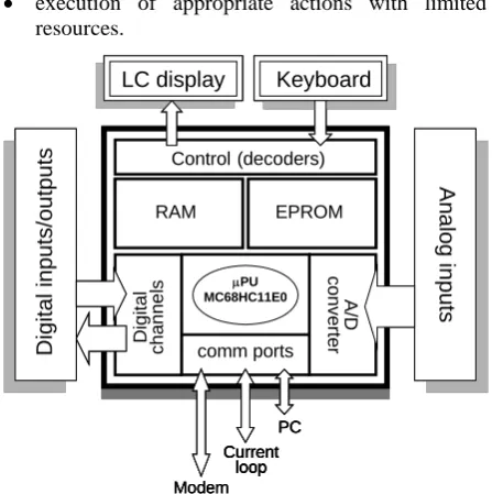
Modern manufacturing faces two main challenges: more quality at lower prices and the need to improve productivity. Those are the requirements to keep ma-nufacturing plants in developed countries, facing the competition from the low-salary regions of the world. Other very important characteristics of the manufactu-ring systems are flexibility and agility of the produc-tion process using present equipment and technology [11]. Current computer control facilities are networks of programmable logic controllers, microcomputer-based distributed control systems and real-time cont-rollers [3]. For control and monitoring of copper pro-duction process in smelting plants in Bor (Serbia), a complex distributed control system was developed. The microprocessor measuring station – MMS is an industrial programmable logic controller (PLC) and a core of a process control and monitoring system [9]. In functional point of view, it is an autonomous unit, which is used in technological process with the aim of data acquisition and command execution. The overall block diagram (Figure 1) shows hardware bases as a modular unit with CPU and I/O assemblies. The CPU module is a one-board computer (OBC) containing the MC68HC11 microcontroller [6]. Software control program is a residential executive code situated in ex-ternal EPROM. This is a complex operational program with few global functions:
• management of all hardware resources and control of those functions,
• interaction with an environment which has time-varying properties,
• execution of appropriate actions with limited resources.
Control (decoders)
Di
git
a
l
cha
nnel
s
A
/D
conve
rte
r
comm ports
μPU MC68HC11E0
RAM EPROM
An
alog
inpu
ts
Di
gital inputs/outputs
LC display Keyboard
Modem PC Current
loop
Control (decoders)
Di
git
a
l
cha
nnel
s
A
/D
conve
rte
r
comm ports
μPU MC68HC11E0
RAM
RAM EPROMEPROM
An
alog
inpu
ts
Di
gital inputs/outputs
LC display Keyboard LC display Keyboard
Modem PC Current
loop Modem
PC Current
loop PC Current
loop
Figure 1. Overall block diagram of MMS CPU
The ability of the MMS to meet demands above depends on its capacity to perform the necessary acti-vities in the given time. To achieve given goals, executive system has to solve many requirements, which are a result of different events, often unex-pected and irregular [4]. RAM on CPU board is used for storing of dynamical parameters and processing of data information.
64 + 64 digital state signals (input + output) with mutual point (or independent), RS232 communication port, 48 (56) KB for data (RAM), 16 (8) KB for software (EPROM). LC display and functional key-board give a possibility of local device control, time synchronization and start of measuring. In usual confi-guration, MMS is connected to PC, which is a remote workstation. MMS can operate independently of monitoring computer and control the process itself. It can also work as data logger, and store over 3000 data messages in local RAM, and later, when connection to a monitoring PC is established, transfer them to PC. EPROM of MMS holds residential software (firm-ware), which is often known as an executive system. It consists of executable versions of test, control, opera-tional and communication software modules. Opera-tional program module is responsible for measuring of analog channels and checking of states of digital inputs. The type of measuring, sampling rate and other parameters can be changed using local keyboard, or commanded from a monitoring PC. The message is transferred to monitoring PC, or stored in local RAM (if PC is disconnected). If any parameter exceeds given limits, it causes an alarm message, or even better, if any parameter shows trend of reaching limit value, it can firstly cause a warning message, so the operator, or the system itself can react on time.
2. The Structure of MMS Software
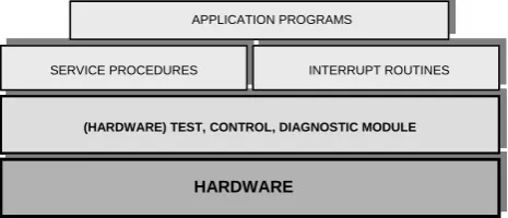
MMS software is organized as a real time execu-tive system. It is written in symbolic language – assembler for M6800 and P-assembler for Intel PC [12]. There are three basic categories of program mo-dules: test – control and diagnostic module, service and executive program modules and application prog-rams, as presented in Figure 2.
HARDWARE
(HARDWARE) TEST, CONTROL, DIAGNOSTIC MODULE SERVICE PROCEDURES
INTERRUPT ROUTINES
INTERRUPT ROUTINES APPLICATION PROGRAMS
HARDWARE
(HARDWARE) TEST, CONTROL, DIAGNOSTIC MODULE SERVICE PROCEDURES
INTERRUPT ROUTINES
INTERRUPT ROUTINES APPLICATION PROGRAMS
Figure 2. Structure of MMS software
Test – control programs check whether device hardware work properly testing CPU by checking correctness of performing of instruction set. After suc-cessful processor and voltage supply testing, a me-mory test is carried out by using logic EXOR function to check a control character of an executive code included in EPROM. RAM is tested by writing and reading of the appropriate content in each location. Timer operation order and interrupt routines are also checked. Those tests are named POST – power on
self-test [2]. Control and diagnostic software module contains procedures for tests of on-line function cor-rectness. Those tests are known as built-in self tests (BIST) [2]. The typical one is a test of A/D conver-sion. The hardware A/D converter adjustment provides digital output between 01 and FE (hex). While MMS is measuring, the control procedure examines every ADC result and, if it is out of range (01 – FE hex), error flag is set and result is ignored.
The main part of executive system is a complex program module, which contains the service proce-dures and interrupt routines. It has to solve the fol-lowing three key functions: task or process schedu-ling, resources dispatching and interaction between different tasks (intertask communication). Kernel is the smallest part of executive system, which is plan-ning execution of tasks as a consequence of events. Two principles are in use: polling and interrupt mechanism. Polling method examines semaphores determining a characteristic states or status. If it is necessary, the appropriate procedure executes tasks dedicated to that event, otherwise the polling loop is executing again. Polling is in use to maintain local peripherals (micro switches, functional keyboard and LCD). Polling mechanism is also used for transfer of message to PC and sampling (measuring).
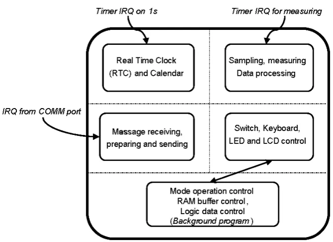
The coordination and synchronization of different tasks execution is possible to achieve using an interrupt mechanism. Interrupt requests (IRQ) can occur in synchronous time intervals, periodically (cyclic), asynchronous, stochastically, or combinatio-nal, as in MMS case. There are different sources of IRQ: from timer (for local real time clock – RTC and for measuring, to initiate inputs sampling), and from serial communication port. Timer IRQ is periodical, while communication IRQ is stochastic from MMS point of view [7], (Figure 3). The MC68HC11 can support different interrupt requests, but not at the same time (concurrently). This means that there is a priority order for interrupt servicing. There are two groups of interrupts: nonmaskable and maskable. Some of them may be permanent or temporary disabled, using a mask in CCR register [6]. Nonmaskable interrupts (total 6) have a higher priority, but for remaining (20) maskable interrupts it is possible to arrange the priorities using the HPRIO register. For any of the interrupt sources, there is an unique entry in interrupt vector table [6].
The application program (working module) is run-ning as a complex endless loop. It checks the contents of a set of control registers and activates appropriate procedures and routines accordingly [9] (see Figure 3).
the occurring of many interrupt requests at the same time. The timer IRQ for measuring occur at regular time intervals depending on desired sampling rate. But the communication IRQ may happen at arbitrary
mo-ment. This means that it is possible to miss some of demands for measuring or communications. To de-crease this possibility, it is necessary to make good synchronization of those events, as much as possible.
Figure 3. The relations between SW modules (State Chart)
3. One Way of Task Scheduling
During power on or reset sequence, some of memory zones are filled with appropriate contents. When the resident executable module in EPROM is used, the adequate addresses of beginning of interrupt service routines (ISR) for different requests are written into interrupt vector table (IVT) on the highest memory addresses. Using declaration shown in Figure 4, a symbolic language compiler calculates starting addresses of every routine, and they are written together with the other executable program modules in RAM or EPROM [9].
CommInterr = $ffd6; {communications IRQ} (#InterrComm);
InterrTimer1 = $ffe8; {Timer 1 IRQ} (#TimerInterr1);
InterrTimer2 = $ffe6; {Timer 2 IRQ} (#TimerInterr2);
InterrTimer3 = $ffe4; {Timer 3 IRQ} (#TimerInterr3)
InterrTimer4 = $ffe2; {Timer 4 IRQ} (#TimerInterr4);
Reset = $fffe; {Power On or Reset} (#ProgrammStart);
END.
Figure 4. Definition of interrupt vector table
The MMS is connected to PC in an elementary network via asynchronous serial communications port
(direct cable is usually used). If transfer rate is 19200 bps, the duration of one character transmission is about 0.5 ms (Tch = 0.5ms). For the shortest message of 11 characters (Nch = 11), transmission time is:
Tm = Nch ∗ Tch ≈ 5.5 ms (1)
and for the longest one (Nch = 153) [10], Tm ≈ 76.5 ms. The message is not transmited in parts, rather as an entity. This means that the communication session is not interruptible. In fact, not for a long time! But for a couple of μs it is possible to stop the transfer control and service a timer interrupt request, in order to set the appropriate flag in desired register. After this operation, the communication session may continue.
The measuring procedure (sampling) has two parts: preparation and execution. Preparation is a small program sequence of preparing control registers, timely optimized. Measuring execution contains read-ing of inputs, A/D conversion and result orderread-ing. The 8-channel sampling requires less than 0.2 ms of time.
serial port on MMS is quite stochastic comparing to regular periodic timer requests for sampling. Because the communication session has to be completed at once, its interruption is not allowed. The timer IRQ is
masked at the start of communication interrupt hand-ling routine (IHR), and enabled after the end of transfer.
Figure 5. Time diagram of measuring and communication synchronization
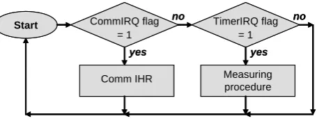
It could be seen that the communication is more significant task than measuring, and hence it has a higher priority. To achieve this goal, the position priority principle is used [1]. It means that after every communication session, or measuring procedure, the flag CommIRQ in communication status register (CSR) [8] is checked first. If it is set, communication session starts again (Figure 6).
yes
Start CommIRQ flag
= 1
Comm IHR
TimerIRQ flag = 1
Measuring procedure
yes
no no
yes
Start CommIRQ flag
= 1
Comm IHR
TimerIRQ flag = 1
Measuring procedure
yes
no no
Figure 6. The position priority ordering
Some applications demand very often and uniform measuring, hence it is not possible to delay the start of measuring (or not to long). There are many solutions for this case. Three of them are practically implemen-ted: a) using the shorter messages, b) more frequent communications requests, and c) data acquisition and uploading.
a) If it is really necessary to measure exactly at time (or nearly), then duration of uninterruptible data transfer must be shorter. Because the transfer rate is limited (19200 bps), the number of characters to be transferred must be decreased. It is achieved by selection of the most important process parameters to be measured. For 8 parameters, the communica-tion session takes about 13 ms. In the worse case, the measuring can start with that time interval delay.
b) The PC initiates every communication session [5]. Successful transfer requires correct addressing, start, data transfer and end of session. If any of those phases are missing, or faulty, the session
starts again [10]. Because measuring has now higher priority, while it runs, the CommIRQ is masked. Unsuccessful data transfer may happen sometimes. It is shown in practice that, if frequency of communication is tripled, this problem is solved.
c) If there is no need for immediate data on PC, the MMS can run off-line, as a data logger [9]. Mea-suring is the main MMS function, and must be done without disturbance of other events like com-munication. After measuring and collection, data are transferred to subordinated PC (uploading). Which of these three methods will be used de-pends on concrete requests and possibilities.
4. Conclusion
The MMS is developed and designed basically for monitoring and control of technological processes in metallurgy, especially for copper production plants. The process parameters changes are not so dynamic, and the response time varies from few seconds up to a couple of minutes. Used in such conditions, the MMS works very stable and reliable. The most demanded practical usage (electrical power monitoring) with one-second sampling rate, operates with 100 ms communication interval. The average loss of data is less than two data messages per day, which is less than 2 / (60 x 60 x 24) = 0.0025 % [5]. The data message shortage sometimes is a consequence of bad transmission. Hence, the appropriate mechanism on dedicated PC software generates the missing message using the interpolation method.
associated PC. Those two make an unique entity – elementary node. The described solutions of MMS event priority sheduling give satisfactory results when applied in real industrial environment.
References
[1] G.C. Barney. Intelligent Instrumentation: Micropro-cessor Applications in Measurement and Control. Prentice Hall, Hertfordshire, 1988.
[2] B. Djordjevic, M. Jevtic, M. Damnjanovic. Digital Real-Time Systems Testing. In: Charisma, Evidenz und Caritas, Ruhr-Universität Bochum, Germany, A31-A40, 1997.
[3] G. Hassapis. Implementation of model predictive control using real-time multiprocessing computing. Microprocessors and Microsystems, Vol.27, Issue 7, 2003, 327-340.
[4] M. Joseph. Real-Time Systems – Specifications, Veri-fications and Analysis. Prentice Hall International, UK, 1996.
[5] D. Karabasevic, V. Tasic, D. Milivojevic. Universal measuring program. Proceedings of the Conference YUINFO 2004, Kopaonik, Serbia, 61, 2004, (in Serbian).
[6] M68HC11 Reference Manual. Motorola Inc, 1990.
[7] D.R. Milivojevic, V. Tasic. Some Software Elements of the Microprocessor Measuring Station. Acta electro-technica et informatica, Vol.7, No.2, 2007.
[8] D.R. Milivojevic, V. Tasic. MMS in Real Industrial Network. Information Technology and Control, Vol.36, No.3, 2007, 318 – 322.
[9] D.R. Milivojevic, B. Lazic, V. Tasic. Mobile measu-ring station. Proceedings of the Conference ETRAN 2000, Soko Banja, Serbia, ML 3, 2000, 255-257, (in Serbian).
[10] D.R. Milivojevic, V. Tasic, D. Karabasevic. Com-munication in realized RTS systems. Proceedings of the Conference ETRAN 2003, Herceg Novi, Monte-negro, 2003, (in Serbian).
[11] J.N. Pires. Semi-autonomous manufacturing systems: The role of the human–machine interface software and of the manufacturing tracking software. Mechatronics, Vol.15, Issue 10, 2005, 1191-1205.
[12] Z. Radonjic. ∏-assembler user guide. Nis, Serbia, 1996, (in Serbian).