Gray Level of FIC using Zero-Mean Method
Eman A. Al-Hilo
Kufa University/College of Education for Girls Kufa/Iraq Email: [email protected]
Hawraa H. Al-Laythawe
Kufa University/College of Education for Girls Kufa/Iraq Email: [email protected]
Abstract – In this work, a fractal image compression (FIC) based on zero-mean block matching method is adopted. In this method the mean of the range blocks is used instead of traditional offset parameter. The parameter (r ) has a smaller dynamic range [0,255] than the (o) parameter [-255,511] which using in traditional method. This may cause large errors in some image regions (or points) especially those which belong to high contrast area. Replace this factors also reduces and simplifies the computations of the affine parameters during the encoding process. The test results conducted on 24 bits/pixel gray Cat image indicated that the encoding time (7.47) sec, compression ratio (5.63) ,PSNR (35.16) .
Keywords – Image Compression, Fractal Image Compression, Zero-Mean.
I.
I
NTRODUCTIONThe idea of fractal image compression (FIC) was originally introduced by Barnsley [1] and the first practical FIC scheme was realized by Jacquin in 1992 [2] .The underlying premise is based on the partitioned iteration function system (PIFS) which utilized the self-similarity property in the image to achieve the purpose of compression .Using fractal transform, higher image compression ratio can be achieved but the encoding time also increases. The encoding process of the fractal image compression is time-consuming. The reason is that most of the encoding time is spent on a large amount of computations of similarity measure. [3]
The focus of major research in fractal image compression is on improving the speed of compression while keeping the quality of decompressed image comparable to the existing schemes. Here it described a review of new techniques of fractal image compression to improve the speed of compression as well as the quality of an encoded image.[4]
In FIC the image to be encoded is partitioned into blocks called (ranges). Each range is coded by reference to some other part of the image called (domain). The number of ranges plays an important role in the compression ratio, encoding time and reconstructed image quality. After generating the range and domain pools, the matching process implies for each range block, with all domain blocks (D) are listed in domain pool, by performing a set of affine transformations.[5]
Recently some improvements and modifications have been studied which made the fractal technique a challenging candidate its encoding time needs to be reduced. One of the introduced improvements is based on zero-mean block matching method, which utilizes unconventional affine mapping.. In this work, an enhanced zero-mean fractal coding scheme for gray images is introduced.[8]
II.
IFS
C
ODING OFZ
ERO-M
EANB
LOCKAfter the generation of the range and domain pools; the following obtained: Partitioned rang (range blocks) partitioned domain (domain blocks), and of course the size of each block which is same in the two cases as mentioned before. Now, one takes each range block listed in the range pool and map it with all the domain blocks listed in the domain pool. At each mapping instance one determines the mapping coefficients, i.e., scale (s) and offset (o), which are called the IFS coefficient. The offset factor is determined using traditional affain mapping, described by equation
r
i
sd
i
o
,……… (1)has wide dynamic range (i.e., [-255,510]), this may cause large errors in some image regions (or points) especially those which belong to high contrast area. The results of the analysis conducted in this research work indicate that the traditional offset factors require an additional bit (sign-bit). Also, the analysis results indicate that the correlation between the offset coefficients of the adjacent blocks is week and not similar to that found between the average brightness of the adjacent blocks. Normally, the offset values of the block should be correlated with average brightness values of blocks. So, to handle this disadvantage a change in IFS mapping equation was performed. By applying averaging on both the range and domain blocks in equation (1) the following equation is obtained [8]
, ... (2) here,
, …...……… (3)
, …..………... (4)
The subtraction of equation (2) from equation (1) leads to:
, ………..… (5)
So, this contractive affine transform could be rewritten to become in the form:
, ....……….… (6)
From equation (6), the fractal parameters become (s) and ( ) instead of the of the conventional (s) and (o) coefficients in traditional IFS mapping equation.
The scale (s) parameter could be determined by applying the least mean square difference ( ) between
the approximated ( ) and actual ( ) values [6]:
, ……….. (7)
, .…………..……. (8)
o
d
s
r
1
0 1 m
i i
r m
r
1
0
1 m
i i
d m d
d
s
sd
r
r
i
i
d d
rs
ri i
r
2
i
r
r
i
1
0
2
2 1 m
i i i
r r m
0
2
s
The straight forward manipulation for equations (7), (8) leads to:
, …….… (9)
.……… (10)
where,
, ………… (11)
and,
, …………... (12)
III.
Q
UANTIZATIONQuantization is simply the process of reducing the number of bits needed to store coefficient values by reducing its precision (i.e, rounding from float type to
integer). Before the determination of the values of ( ),
the values of the scale (s) and offset ( ) coefficients should be limited and quantized as follows:
1. The value of the offset should be bounded within the
interval , where and are
the lower and upper boundaries of the permissible values of offset; they should always be within the range [0,255].
2. Also, the values of scale (s) parameters should be
bounded within the interval , where
and are the lower and upper boundaries of the permissible values of the scale. that the value of the
minimum scale ( ) must be not less than (-1), while the maximum scale value ( ) must be not more than (1).
3. The coefficient should be quantized by using the following equations [6]:
…(13) …………. (14)
, ……… (15)
where, is the number of allocated bits to represent the
quantization index of the average brightness ( ) coefficient.
is the quantization step of the brightness ( ) coefficients.
is the quantization index of the brightness ( ) coefficient.
is the quantized value of the brightness ( ) coefficient.
4. The scale value should be quantized by using the following equations [6]:
, …….. (16)
, ... (17)
…….. (18)
where, is the greatest permissible value of scale coefficient.
is the lowest permissible value of scale coefficient.
is the number of allocated bits to represent the quantization index of the scale coefficient.
is the quantization step of the scale coefficient.
is the quantization index of the scale coefficient.
is the quantized value of the scale coefficient.
IV.
I
SOMETRICP
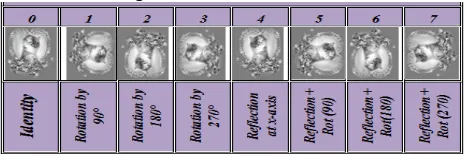
ROCESSIn order to increase the size of domain pool and, consequently, to increase the probability of finding the best (near optimal) approximations for the range blocks, each domain block is transformed by using a set of isometric transforms (i.e., rotation and flipping), such that eight versions (blocks) are produced for each domain block [9]. (see table (1)).
The main disadvantage of using the isometric mappings in the encoding process is that more computational time will be required to perform the extra matching processes.
Table 1: The eight isometric transformations
V.
G
ENERATINGI
FSC
ODINGEncoding method could be summarized by the following steps:[7]
1. Loading BMP image.
a. Establishing the range image (array).
b. Down sampling the range image to produce the domain array.
c. Partitioning:
(1) The range array must be partitioned into non-overlapping fixed blocks, to generate the range blocks (r1,….,rn).
(2) The domain must be partitioned into overlapping blocks, using specific step size, to generate the domain blocks (d1,…,dn), they should have the same size of range blocks.
d. Searching: 0 0 0 1 2 2 2 1 0 d d d m
i i i
if if d r r d m s
1 0 2 2 2 2 2 m i i i dr dr
m r d s s
1 0 2 2 2 1 mi i
d d d
m
1 0 2 2 1 mi i r r m
2 r
r
maxmin
r
r
r
r
minr
maxmax min s s
s
max
s
sminmin s max s
r
1 2 255 o b o Q o o Q o round i o oq
i
Q
o
o br
o Qr
oi
r
qo
r
min max min max 1 1 2 1 2 s s if s s s s if s Q S S b Min Max b Max s s S Q s round i s s q i Q(1) Calculating the average rang which is the average of each range block.
(2) Quantizing average rang according to equations (13, 15).
(3) Picking up a domain block from the domain pool. (4) Performing one of the isometric mappings.
(5) Calculating the scale (s) coefficient by using equation (9).
(6) Applying the following condition to bound the value of (s) coefficient:
If s< smin then s=smin
Else if s >smax then s=smax
End if
(7) Quantizing the value (s) using equations (16,18).
(8) Computing the approximate error ( ) using equation (10).
(9) After the computation of the IFS code and the sum of
errors ( ) of the matching between the range and the tested domain block that listed in the domain pool,
the ( ) is compared with registered minimum error
( ); such that:
If
2<
min2 then sopt=is;
min2 =
2PosI=domain block index Sym=symmetry index End if
(10)If < then the search across the domain blocks is stopped, and the registered domain block is considered as the best matched block.
(11) Repeating steps (4) to (10) for all symmetry states of the tested domain block.
(12)Repeating steps (3) to (11) for all the domain blocks listed in the domain pool.
(13) The output is the set of IFS parameters
which should be registered as a set of fractal coding parameters for the tested range block.
(14)Repeating steps (1) to (12) for all range blocks listed in the range pool
(15)Storing all IFS mapping parameters as an array of record. The length of this array is equal to the number of range blocks in the range pool.
VI.
D
ECODINGZ
ERO–M
EANM
ETHODThe decoding process can be summarized in the following steps:[7]
1. Generating the first reconstructed domain pool, as a blank image or as a piece of any available image. 2. The values of the indices of (io) for the range blocks
should be mapped (dequantized) to reconstruct the values of
r
by using the dequantization equations (13, 14).3. The values of the indices of (is) for the range blocks
should be mapped to reconstruct the values of (s) by using the dequantization equations (16, 18).
4. Choosing the value of the maximum possible iteration (m), and the value of the threshold of mean square error (TMSE), in our program used (m=20, TMSE=0.04). At each iteration do the following steps:
a. For each range block determine from its corresponding IFS parameter (PosI) the coordinates (xd,yd) of the best
matched domain block in order to extract the domain block (d) from the arbitrary domain image.
b. Calculating
d
for the corresponding domain block. c. For each range block, its approximationr
i
is obtainedaccording to equation (4).
d. The generated
r
i
block is transformed (rotated or reflected or both) according to its corresponding IFS symmetry parameter value (Sym).e. Putting the generated
r
i
block in its position in the decoded image plane (range image).f. Checking whether there are other range blocks need to be reconstructed, if yes then repeat steps (c, d, e). g. Down sampling the reconstructed image (range array)
in order to produce a new domain array by using the averaging (or integer) sampling.
5. Calculating the mean square error (MSE) between the newly reconstructed range and the previous reconstructed range image. If the MSE is greater than the (TMSE) value then the iteration continues, and the steps (a-g) should repeat; till reaching the attractor state (i.e., the reconstructed range image is very similar to the previous reconstructed image). Sometimes, the iteration continues till reaching the predefined maximum number of iterations, without the fulfilment of MSE stopping condition.
6. The above steps (4a-4h) should be applied to produce the attractor of each component separately by using different number of iterations.
7. Calculating the fidelity criteria as mentioned in section (1.8.2), then determines the overall value of the fidelity criteria for the reconstructed image.
VII.
E
XPERIMENTALR
ESULTSThe proposed system was implemented using Visual Basic (Ver. 6.0). It is tested on laptop Hp with (2.40GHZ, RMA 600GB) Windows 7.
The proposed system had been tested using Cat image (256x256 pixel, 24bits) as test image. The value of the parameters MaxAvg ( ) and MinAvg ( ) were fixed in all these tests at (0) and (256) respectively. We take some tests.
1.
Block Size Tests:
Table (2) illustrates the effect of BlockSize on PSNR and CR. Figures (1-7) show the effect of the Block Size parameter on MAD, MSD, RMSE, MaxDiff, PSNR, CR, BitRate and ET.r
r
2
2
2
2 min
2 min
i.e.,is,io, posI,Sym
max
Table 2: Effects of BlockSize on the compression performance parameters
Fig.1. The effect of BlockSize on MAD
Fig.2. The effect of BlockSize on MSD
Fig.3. The effect of BlockSize on PSNR
Fig.4. The effect of BlockSize on MaxDiff
Fig.5. The effect of BlockSize on CR
Fig.6. The effect of BlockSize on BitRate
Fig.7. The effect of BlockSize on encoding time
2.
Jump Step Tests
:
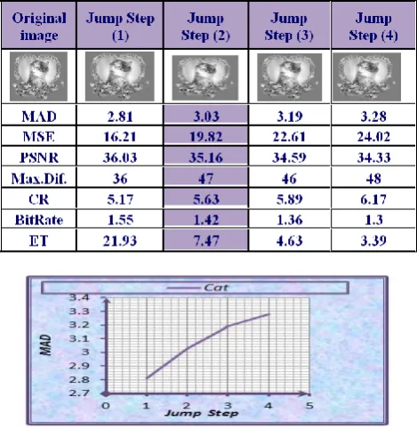
Table (3) shows the effects of JumpStep on the compression performance parameters. Figures (8-14) present the effect of JumpStep on MAD, MSD. RMSE, Max.Dif., PSNR, CR, BitRate and ET respectively.Table 3: Effect of StepSize on the compression performance parameters
Fig.9. The effect of JumpStep on MSD
Fig.10. The effect of JumpStep on MaxDiff
Fig.11. The effect of JumpStep on PSNR
Fig.12. The effect of JumpStep on CR
Fig.13. The effect of JumpStep on BitRate
Fig.14. The effect of JumpStep on encoding time
The figure (15) shown original image and its reconstructed images, where we note that the image quality is not affected by compression where encoding time (7.47) sec, compression ratio (5.63), PSNR (35.16) .
Fig.15. The original image and its reconstructed images
VIII.
C
ONCLUSIONFractal gray image compression using zero-mean block matching method is more effective than the classical IFS mapping method in compressing gray images, The following remarks summarize the noticed behaviour in the above listed results:-
1. BlockSize=(4x4) leads to appropriate PSNR and CR than other sizes.
2. MAD, MSD, MaxDiff , ET and CR increase with the increase of BlockSize.
3. PSNR and BitRate are inversely proportional to BlockSize.
4. The JumpStep value=(2) leads to appropriate CR and PSNR than other JumpStep values.
5. The increase in JumpStep leads to an increase in MAD, MSD, CR and MaxDiff. .
6. PSNR, Bit Rate and ET are inversely proportional to JumpStep.
R
EFERENCES[1] Barnsley MF. “Fractals everywhere”, San Diego: Academic; 1993.
[2] E. Jacquin, “Image coding based on a fractal theory of iterated contractive image transformations,” IEEE Transactions on Image Processing, Vol. 1, 1992
[3] YIH-LON LIN AND WEN-LIN “Fast Search Strategies for Fractal Image Compression” CHEN, Department of Information Engineering, I-Shou University, Kaohsiung, 840 Taiwan, Journal Of Information Science And Engineering 28, 17-30 (2012) [4] R. E. Chaudhari , S. B. Dhok “ Review of Fractal Transform
based Image and Video Compression “St. Francis Institute of Technology Mumbai, Maharashtra India ,, International Journal of Computer Applications (0975 – 8887) Volume 57– No.19, November 2012
[5] Eman Abdul-Jabar Saad “Speeding Up Fractal Image Compression by Reducing Image Size” Electronic Computer Center, Mustansiriyah University, Baghdad, Iraq, Diyala Journal for pure sciences , Vol: 6 No: 4, October 2010 ISSN: 1992-0784 [6] George, L., "IFS Coding for Zero-Mean Image Blocks", Iraqi
Journal of Science, Vol.47, No.1, 2006.
[7] Al-Hilo, E.A., “Speeding-up Fractal Colored Image Compression using Moments Features”, PhD Thesis, College of Science, AL-Mustansiriyah University, Baghdad, 2007. [8] George, L.E., Al-Hilo, E. A.,” Color FIC by Adaptive
Zero-Mean Method” International Symposium on Computing, Communication, and Control (ISCCC 2009) Proc .of CSIT vol.1 ,pp190-196, IACSIT Press, Singapore,2011.
List of Abbreviations Abbreviations Original
CR Compression Ratio
ET Encoding Time
FIC Fractal Image Compression
MAD Mean Absolute Difference
MaxDif. Maximum Difference
MSE Mean Square Error
PSNR Peak Signal to Noise Ratio
A
UTHOR’
SP
ROFILEDr. Eman Al-Hilo
She is born in 1967 at Najaf city, Iraq. She has B.Sc. in Physics, M.Sc. In Molecular Physics, Ph.D in Digital Image Processing.
Now, she is Assistant professor in the College of Education for girls/Physics Department/Kufa University/Iraq. She is interesting in image processing and fractal image compression researes.
Hawraa H. Al-Laythawe
She is born in 1990 at Diwanyia city, Iraq. She has B.Sc. in Physics.