Copyright © 2015 IJECCE, All right reserved
32 Channels Slicing with AM Modulator using LED
Source
Muthana. Y. Aldouri
Department of Computer Technical Engineering, Al-Nisour University College, Baghdad-Iraq
E-mail: [email protected]
Luma. W. Jameel
Department of Computer Technical Engineering, Al-Nisour University College, Baghdad-Iraq
E-mail: [email protected]
Abstract – This paper propose 32 channels to be slicing which is considers one of the most effective solutions to the optical communication system design. The main objective of this paper is to modulate the transmitted signal by using AM modulation technique signal. LED laser input source used with wavelength at 1550 nm, power 1.190mw (0782dBm).Two optical fibers cable were used with reference wavelength =(1550)nm connected two optical amplifiers, gain (20dB), noise figure (4dB) with a media transmission line produces more effect in transmit the signal for long distance which we need. The implementation of this system requiring anew design of OCDMA technique to avoid the suffering system from the problem of multiple access interference (MAI).Slicing technique is used to achieve more channels to the input (32 channel),therefore can obtained many users what we need. And then we can achieve an Optical Code Division Multiplexer (OCDMA) system asynchronous transmission, secure communication, of capacity on demand, and high degree of scalability depending on the stability of this system.
Keyword's – LED Leaser, AM Modulation, 2 Amplifiers, Loop Control, 2 Optical Fiber Cable.
I.
I
NTRODUCTIONThe significant of broadband and multimedia telecommunications is still increasing and the use of fiber –optic technology in the access network is growing very fast in order to meet customers demand. Along with the higher bandwidth demand, increasing number of subscribers.And advances in the Wavelength Division Multiplexing (WDM) device technology.WDM system offers many advantages such as, asynchronous , ability to support variable bit rate, and sociability of the network. This is done in order to obtained using one or more passive and fixed optical splitters in the fiber path [1].
1-Wavelength Division Multiplexer:
The main principle of WDM is thatcontain of two parts multiplexer and DE multiplexer ,the function of multiplexer is to combine a number of standard SONET data channels and generate a series data output.The operation and functional characteristics of the following multiplexer for example are based on the Philips OQ2535HP.this multiplexer combines 32x 78 Mb/s data channels into a single 2.5 Gb/s data stream in compliance with OC48/STM-16 format. Some of the most important operating characteristics of the multiplexer are:1) High input sensitivity. 2) 5v TTL clock output. 3) Low power dispersion. 4) CML data and clock outputs. 5) 3.3v TTL compatible data inputs.
For example if we have five users with different wavelength (U1=1550nm, U2=1550.1nm, U3=1550.2nm, U4=1550.3n, and U 5=1550.4nm), at chip spacing equal to 0.1nm, and these five users data will be collected in the multiplexer device and then send them in one cable to the receiver side , in the receiver there were a second part called DE multiplexer device which is used to submit the cable with data of five users and divide them into five wires towards the detector channelthat mean U1 to the detector 1,U2 to detector 2,U3 to detector 3, U4 to detector 4 and U5 to detector 5. In the past there were a compiler working as a multiplexer, and splitter working as a divider, but the difference is that they modified the techniques of splitter and compiler and using instead of them a multiplexer and DE multiplexer just setting a high quality filters built in them. So by using the DWM technique we can decreases the noise and attenuation in the data .Figure 1.below shoes the WDM technique which clearly appear the working of multiplexer and De multiplexer, depending on the number of users (λ).
Figure1.block diagram of WDM long –haul.
Benefit of WDM: WDM technology allows multiple connections over one fiber thus reducing fiber plant requirement. This is mainly beneficial for long-haul application, campus application requires cost benefit analysis .while the WDM technology can also provide fiber redundancy ,and provides a managed fiber service. The main principles of the WDM techniques of the transmitter and receiver transmitted signal will be illustrated clearly in figure 2.abearing two signal visa versa direction for every single pair fibers.
limit of WDM is close to one thousand channels per fibre [4] and today’s systems use 160 channels.
Fig.2. WDM fiber optic transponder.
Many WDM devices and networks are commercially available today. WDM can be used in circuit switching, and the WDM networks commercially available are of this type. However, especially in MAN and LAN networks, using circuit switching is inefficient, because the bit streams are relatively short [5]. Therefore there is a need for optical packet or optical burst switching.
II.
C
HIPS
PACINGChip spacing is the spacing between two weights or non-zero spectrum that is being transmitted in an OCDMA system [2]. Until now, there is no standard spacing for OCDMA systems [3]. In this research, the spacing has been varied to study the effect of it on system’s performance. Usually, with the closer channel spacing, nonlinear effects such as four wave mixing (FWM). Figure 3 shows the example of chip spacing in OCDMA system. The spacing is measured between two adjacent peaks. However in the theoretical development, ideal rectangular shaped weights as in Figure 4 are used.
Chips spacing
1549 .2
1548 .4 1550 .8 1551.6
1550 nm Center Frequency Chips Spacing
.
. 1549 2 1550 8. 1551. 6 1548 4
Fig.4. Ideal Rectangular Shaped Weights.
III.
P
ERFORMANCEA
NALYSISThe performance of OCDMA systems have been investigated for about two decades and received a lot of attention [6-9]. This is due to its excellent performance, such as asynchronous access to the networks [10], high security operation [11], and high capacity in burst networks [12]. In the recent years, optical-spectral-amplitude-coding CDMA (OSCDMA) system attracts more attention because its ability to reduce multiple access interference (MAI) by suing subtraction detection techniques with fixed in-phase cross correlation [13-14].
Optical code-division multiple access (CDMA) systems are in receipt of more and more attractive in the field of all optical communications as multiple users can access the network asynchronously and simultaneously with high level of security. Optical spectrum code-division multiple -access (OSCDMA) is a multiplexing technique tailored from the successful implementation in wireless network [15, 16].
IV.
S
IMULATIONS
ETUPCopyright © 2015 IJECCE, All right reserved divided into two parts, one to the decoder that has an
identical filter with the encoder and the other to the decoder that has the complementary filter .An electrical
subtracted is used to subtract the overlapping data from the wanted one. The performance of the system referring to the bit error rate (BER) at BER analyzer.
RECEIVER 2
DECODER 1 RECEIVER 1
PIN
SUBTRACTOR
ENCODER 2 EXTERNAL MODULATOR
M U L T I P L E X E R DATA 1
ENCODER 1
DATA 2
S P L I T T E R
PIN
PIN
SUBTRACTOR PIN
2
3
3
4
2
3
3
3
4
DECODER 2
0110
X
1100
Y
3
Fig.5. Simulation Setup for AND Subtraction Detection Technique.
V.
P
RESENTATIONA
NALYSISReferring to fig 4 we can see that we can transmit the data for more than 100 km, at very stable system depending on the system designed . The transmitter uses a LED source with a maximum optics power of 6 dBm and a wavelength of 1550 nm. To ensure the linearity of the system, the LED is properly biased and the peak-to-peak voltage of the input signal cannot exceed the specified values. So it’s illustrated that at 110km maximum distance we can reached in this system data can transfer clearly as BER equal to the value of 4.8xe-4while in the 10 km the BER will be at value of 7.53x10⁻¹⁷ at fiber cable No1constant at 10 Km, while at cable No 2 constant at maximum length equal to 50Km the BER referring to the value of 5.2 x10⁻⁵ at 60 Km maximum, and BER equal to 1.9x10⁻¹³ minimum length we can declare that this is a good result for this system. For these results the following parameters were used: line width thermal noise=
1012 Hz; electrical bandwidth = 80 MHz at the operating wavelength of 1550 nm. The performance of the system referring to the bit error rate (BER) at BER analyzer. With the same setup, we place the EDFA with 20 dB gain, immediately after the transmitter to launch power signals into the fiber to see the difference of performance on FTTH system by using OSCDMA multiplexing scheme [17].
Fig.6. Relation between two fiber length and BER.
Fig.7. Relation between fiber length and BER both two fibers
This figure referring to the relation when combined the two fibers and the bit error rate (BER) at constant bit rate at 622MHz. As we see from this graph the minimum length equal to 20 Km the eye diagram referring to the value of BER =5.94x 10 -17 , and in the same graph at the maximum distance fiber length equal to 120Km the BER equal to 4.3x10⁻⁴, this values is more relabel for this system.
Fig.8. Power spectrum at 100Km (-38dBm)
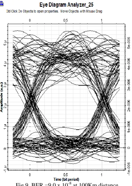
Fig 9. BER =9.0 x 10⁻⁸ at 100Km distance
Copyright © 2015 IJECCE, All right reserved Fig.11. power spectrum at (-24dBm)
Figures (10 &11) referring to the eye diagram and power spectrum which is giving a quick examination of the quality optical output signal, its clearlyfoundthe measuring values at low distance equals to 20 Km , and the BER will be at value 5.9x10⁻¹⁷ besides the power spectrum reaching the value of -24 dBm.
VI.
C
ONCLUSIONThe unlicensed, higher speed, broader and unlimited bandwidth, low cost solution, and shortest deployment time frame are some of this system which is built or designed to get 32 channels output ,is make use of many users collected in this system besides the distance reaches to approximately 100 Km is very good distance comparing with the other systems, besides using LED in the source make the system very low cost.
R
EFERENCES[1] Josepprat: Next-Generation FTTH passive Optical Networks. Springer science Business Media B.V.2008.
[2] Prucnal, P., Santoro, M. & Ting, F. (1986). Spread spectrum fiber optic local area network using optical processing. J. Lightwave Technol., LT-4, 547-554.
[3] Scott, R.P., Cong, W., Li, K., Hernandez, V.J., Kolner, B.H., Heritage, J.P., and Yoo, S.J.B, 2004
[4] R. Mollard, “COSC460 Report: Medium Access Control Protocols for WDM Optical Networks”, Honours Report, University of Canterbury, 2001.
[5] K. Seppänen, “Distributed optical frame synchronised ring, an efficient multi-service packet network”, In SSRGG 2001 - International Conference on Advances in Infrastructure for Electronic Business, Science, and Education on the Internet, 2001.
[6] S. V. Maric, O. Moreno, and C. J. Corrada, “Multimedia Transmission in Fiber-Optic,” Journal of Lightwave Technology
vol. 14, no. 10, pp. 2149-2153, October. 1996
[7] S. V. Maric, Z. I. Kostie, and E. I. Titlebaum, “A New Family of Optical Code Sequence for Use in Spread-Spectrum Fiber Optic Local Area Networks,” IEEE Transactions on Communications vol. 41, pp. 1217-1221, August, 1993. [8] S. A. Aljunid, M. Ismail, B. M. Ali, A. R. Ramli, and M. K.
Abdullah, “A New Family of Optical Code Sequences For Spectral-Amplitude-Coding Optical CDMA Systems,”IEEE Photonics Technology Letters vol. 16, no.10, 2383-2385, October, 2004.
[9] Z. Wei, H. M. H. Shalaby, and H. Ghafouri-Shiraz, “Modified Quadratic Congruence Codes For Fiber Bragg-Grating-Based Spectral-Amplitude- Coding Optical CDMA Systems,” Journal of Ligthwave Technology vol. 19, 1274–1281, 2001.
[10] M. Y. Liu, and H. W. Taso, “Multirate Asynchronous Optical CDMA System with Product Code,”IEE Proceedings of Communications vol. 149, no. 56, pp. 299-304, 2002
[11] T. H. Shake, “Security Performance of Optical CDMA Against Eaves dropping,” Journal of Lightwave Technology vol. 23, pp.655-670, 2005.
[12] J. A. Salehi, “Code Division Multiple Access Technique in Optical Fiber Network-Part I: Fundamental Principles,”IEEE Transactions on Communications vol. 37, pp.824-833, 1989. [13] L. Xu, I. Glesk, V. Baby, and P. R. Prucnal, “Multiple Access
Interference (MAI) Noise Reduction in A 2D Optical CDMA System Using Ultra fast Optical Thersholding,”Lasers and Electro-Optical Society. The Annual Meeting of the IEEE, vol. 2, pp.591-592, November, 2004.
[14] J-F. Huang, and C-C Yang, “Reductions of Multiple- Access Interference in Fiber-Grating-Based Optical CDMA Netowork,”IEEE Transactions on Communications vol. 50, no. 10, pp. 1680-1687, October, 2002.
[15] X. Zhang, Y. Ji, and X. Chen, Code Routing Technique in Optical Network. Beijing, China: Beijing Univ. Posts & Telecommunications, pp. 416–419.
[16] F.N. Hasoon' S.A. Aljunid “Spectral Amplitude Coding Ocdma Systems Using Enhanced Double Weight Code” Journal of Engineering Science and Technology.Vol. 1, No. 2 (2006) 192- 202