ISSN : 2455-9679
[Ravindra al., 4(12), Dec 2019] Impact Factor : 3.340
IJRTSM
INTERNATIONAL JOURNAL OF RECENT TECHNOLOGY SCIENCE & MANAGEMENT
“THERMAL ANALYSIS OF CAR BRAKE ROTOR BY USING FEA METHOD”
Ravindra Mohan
Associate Professor, Department of Mechanical Engineering, IES College, Bhopal, MP, India
ABSTRACT
The disc brake rotor is a rotating device. Braking is a process which converts the kinetic energy of the vehicle into mechanical energy which must be dissipated in the form of heat. This paper presents the analysis of the thermal stress ,deformation and heat flux at the disc interfaces using a detailed 3-dimensional finite element model of a real car disc brake rotor . Finite element (FE) models of the brake-disc rotor are created using CATIAV5R20 and simulated using ANSYS 19.2 which is based on the finite element method (FEM). It is also investigates different levels in modeling a disc brake rotor system and simulating contact pressure distributions . It covers Finite Element Method approaches in the automotive industry the contact analysis and thermal analysis. The effect of the angular velocity and the contact pressure distribution on disc brake rotor are investigated. In our project we take different materials like Gray Cast Iron Alloy, ALSI 398, and Al6060 and Composite materials Carbon fibre. Finally comparison between these materials and carried out stresses and deformations level maximum and minimum then we have find out Carbon fiber is best materials other than materials because its light weight and durable.
Key Words: Gray Cast Iron , Al6060, AlSi398, Carbon fiber, Thermal Stresses, Thermal Deformation, Heat flux, Tempreture, Pressure , Disc brake rotor, CATIA, ANSYS.
I.
I
NTRODUCTIONThe brakes designed for the purpose of racing need to have very high braking efficiency. The wear and tear of the pads or the cost is not of great concern to the manufacturer of the racing car brakes. Initially the automobiles employed drum brakes in the cars. The main focus of this thesis is not for the passenger
car technology but it concentrates on the automotive racing industry, NASCAR, the Nation Association of Stock Car Racing. NASCAR is a racing league similar to other racing leagues like Formula 1. The words “Stock Car” are complete purpose built race cars whose only similarity to the production vehicles replicate in exterior side profile. Major vehicle systems are designed for their specific racing purposes [2]. The chassis used by the racing car is full tube frame while that used on commercial vehicles is made of single body frame.
Another difference is the drive train; race versions have eight cylinder engines with rear wheel drive whereas commercial vehicles are four or six cylinder engines with front wheel drive.
ISSN : 2455-9679
[Ravindra al., 4(12), Dec 2019] Impact Factor : 3.340
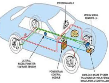
1.1 How Do disk brakes work? How do disk brakes work?
Disk brakes convert kinetic energy from the car into thermal energy by friction
Figure 1.2 Disc brake systems
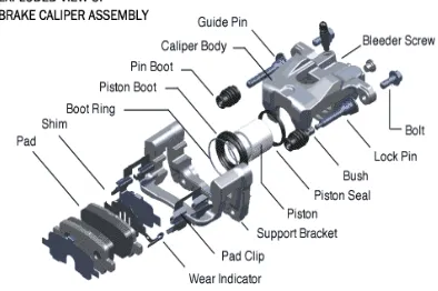
1.2 Brake Caliper Brake Caliper
The brake fluid compresses the piston inside the brake caliper applying pressure to the brake pads.
Figure 1.3 Brake Caliper Assembly Systems
1.3 Brake Rotors Brake Rotors
Connected to the axel – rotating at the same speed as the wheel
Generally made out of steel
Commonly slotted or drilled for extra heat dissipation
ISSN : 2455-9679
[Ravindra al., 4(12), Dec 2019] Impact Factor : 3.340
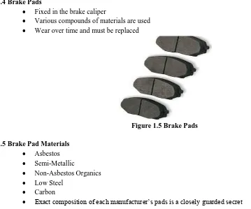
1.4 Brake Pads Brake Pads
Fixed in the brake caliper
Various compounds of materials are used
Wear over time and must be replaced
Figure 1.5 Brake Pads
1.5 Brake Pad Materials Brake Pad Materials
Asbestos
Semi-Metallic
Non-Asbestos Organics
Low Steel
Carbon
Exact composition of each manufacturer’s pads is a closely guarded secret
II. PROBLEM
IN
BRAKE
ROTORS
On studying the background of brakes the main purpose of conducting this research work was finalized. The main objective was to propose a conceptual design for a disc brake rotor using exiting material Aluminium Alloy, Titanium, Gray Cast iron Alloy and New materials Carbon fiber, called a modular brake caliper. The efficient working of brake system depends on how the brake behaves at high temperatures. Thus the aim of the research work will be to reduce the thermal deformation in the modular brake rotor. Since Gray Cast iron hard to machine, modular caliper will be developed as an assembly instead of single block design.
III.
OBJECTIVES
Disc brake noise and vibration generation during braking has been one of the most important issues and definitely worrying problem to automotive manufacturers. Despite brake noise is not a safety issue and has little impact on braking performance, it gives customers the impression of underlying quality problems of the vehicle. In addition, the customers view that the noise emitted from the brake system is indicator of malfunctioning condition and consequently lose confidence on the quality of the vehicles.
IV.
MATERIALS
4.1 Material Selection
ISSN : 2455-9679
[Ravindra al., 4(12), Dec 2019] Impact Factor : 3.340
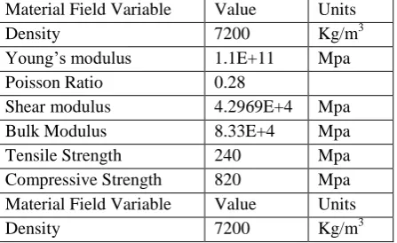
Table- 1 Gray Cast Iron Alloy Mechanical properties Material Field Variable Value Units
Density 7200 Kg/m3
Young’s modulus 1.1E+11 Mpa
Poisson Ratio 0.28
Shear modulus 4.2969E+4 Mpa
Bulk Modulus 8.33E+4 Mpa
Tensile Strength 240 Mpa
Compressive Strength 820 Mpa
Material Field Variable Value Units
Density 7200 Kg/m3
Table- 2 Aluminium Alloy-6060 materials Mechanical properties
Density 2700 Kg/cm³
Melting Point 655 °C
Thermal Expansion 23.4 x10^-6 /K Thermal Conductivity 209 W/m.K
Specific heat 910 J/kg K
Tensile Strength: Ultimate 160 MPa Tensile Strength: Yield 110 MPa Elastic (Young's, Tensile)
Modulus
68 GPa
Poisson ratio 0.33
Table- 3 Carbon Fiber materials Mechanical properties
Material Field Variable Value Units
Density 1950 Kg/m³
Young’s Modulus 300000 MPa
Poisson Ratio 0.30
Tensile Strength 5090 MPa
Compressive strength 1793 MPa
Table 4 Al-Si Alloy (MSFC 398) Mechanical properties (MSFC 398)-
Material Field Variable Value Units
Density 2760 Kg/m3
Young’s modulus 5.54E+10 MPa
Poisson Ratio 0.3
Shear modulus 4.6167E+10 MPa
Bulk Modulus 2.1308E+10 MPa
Tensile Yield Strength 97 MPa
Tensile ultimate Strength 200 MPa
ISSN : 2455-9679
[Ravindra al., 4(12), Dec 2019] Impact Factor : 3.340
V.
MODELING
&
SIMULATION
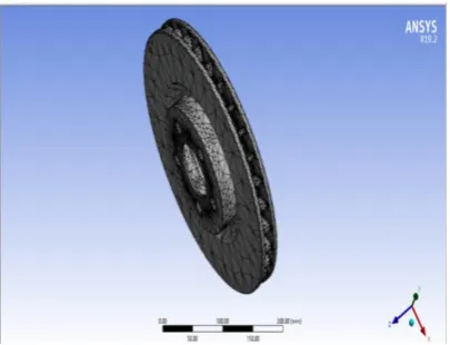
Figure 5.1 CAD Model generate in CATIA Figure 5.2 CAD Model import in ANSYS
and generate meshing
Figure 5.3 Applied boundary conditions on Cast Iron fiber materials
Figure 5.4 Thermal stresses in Cast iron Brake Rotor
Figure 5.5 Deformation in Cast iron Brake Rotor
ISSN : 2455-9679
[Ravindra al., 4(12), Dec 2019] Impact Factor : 3.340
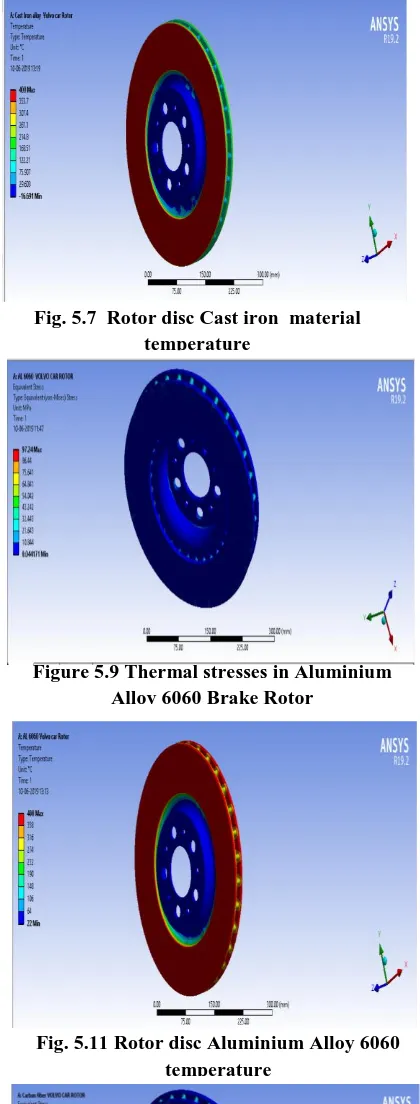
Fig. 5.7 Rotor disc Cast iron material
temperature
Fig. 5.8 Rotor disc Cast iron material heat flux
Figure 5.9 Thermal stresses in Aluminium Alloy 6060 Brake Rotor
Figure 5.10 Deformation in Aluminium Alloy 6060 Brake Rotor
Fig. 5.11 Rotor disc Aluminium Alloy 6060 temperature
Fig. 5.12 Rotor disc Aluminium Alloy 6060 heat flux
ISSN : 2455-9679
[Ravindra al., 4(12), Dec 2019] Impact Factor : 3.340
Fig. 5.15 Rotor disc Carbon Fiber
temperature
Fig. 5.16 Rotor disc Carbon Fiber heat flux
Fig. 5.17 Rotor disc AL SI 398 Alloy thermal stresses
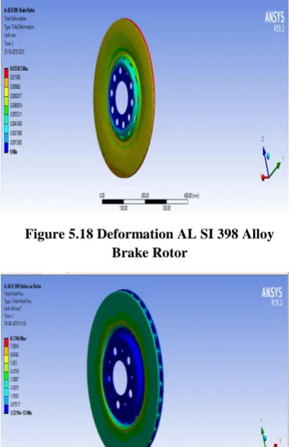
Figure 5.18 Deformation AL SI 398 Alloy Brake Rotor
Fig. 5.19 Rotor disc AL SI 398 Alloy Brake Rotor temperature
ISSN : 2455-9679
[Ravindra al., 4(12), Dec 2019] Impact Factor : 3.340
VI.
ANALYTICAL
CALCULATION
CAR
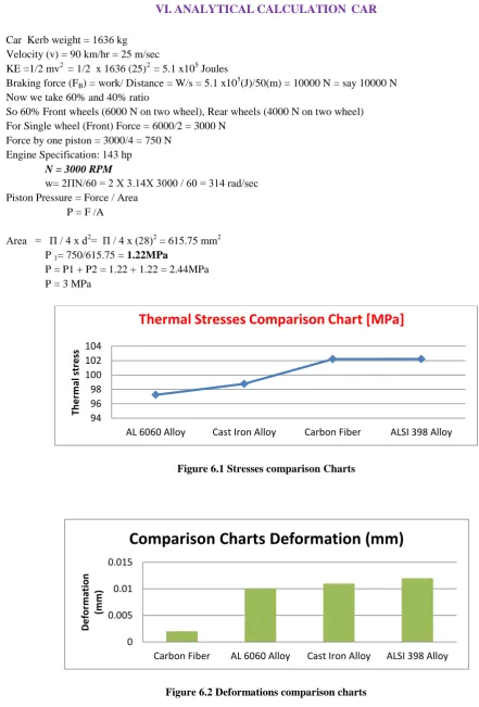
Car Kerb weight = 1636 kg Velocity (v) = 90 km/hr = 25 m/sec
KE =1/2 mv2 = 1/2 x 1636 (25)2 = 5.1 x10⁵ Joules
Braking force (FB) = work/ Distance = W/s = 5.1 x10⁵(J)/50(m) = 10000 N = say 10000 N Now we take 60% and 40% ratio
So 60% Front wheels (6000 N on two wheel), Rear wheels (4000 N on two wheel) For Single wheel (Front) Force = 6000/2 = 3000 N
Force by one piston = 3000/4 = 750 N Engine Specification: 143 hp
N = 3000 RPM
w= 2ПN/60 = 2 X 3.14X 3000 / 60 = 314 rad/sec Piston Pressure = Force / Area
P = F /A
Area = П / 4 x d2= П / 4 x (28)2 = 615.75 mm2 P 1= 750/615.75 = 1.22MPa
P = P1 + P2 = 1.22 + 1.22 = 2.44MPa P = 3 MPa
Figure 6.1 Stresses comparison Charts
Figure 6.2 Deformations comparison charts 94 96 98 100 102 104
AL 6060 Alloy Cast Iron Alloy Carbon Fiber ALSI 398 Alloy
Th e rm al st re ss
Thermal Stresses Comparison Chart [MPa]
0 0.005 0.01 0.015
Carbon Fiber AL 6060 Alloy Cast Iron Alloy ALSI 398 Alloy
D e for m ation (m m )
ISSN : 2455-9679
[Ravindra al., 4(12), Dec 2019] Impact Factor : 3.340
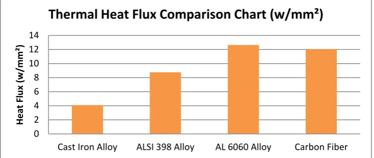
Table 6.3 Thermal Heat Flux Comparison Chart
VII.
RESULT
&
DISCUSSION
We take different four materials and seen that the maximum von misses stress value for All material like Cast Iron Alloy , AL SI 398 , AL-6060 and Carbon Fiber respectively are 98.77 MPa ,102.22 MPa , 97.24 MPa and 102.21 MPa . Here we can cleared observed that AL 6060 materials has considerable value of stresses compare to other materials.
We take different four materials and seen that the maximum deformations value for All material like Cast Iron Alloy , AL SI 398 , AL-6060 and Carbon Fiber respectively respectively are like are 0.011mm , 0.012 mm, 0.01mm and 0.002 mm. Here we can clearly observed that AL6060 materials has very less value of deformation compare to other materials. So it is safe for future design. We take different four materials and seen that the maximum temperature value for All material like Cast Iron Alloy , AL SI 398 , AL-6060 and Carbon Fiber respectively like are 353.7 ⁰C, 357.5 ⁰C, 358⁰C and 357.36 ⁰C . Here we can clearly observed that AL 6060 materials has very less value of temperature compare to other materials. So it is safe for future design.
We take different four materials and seen that the heat flux value for All material like Cast Iron Alloy , AL SI 398 , AL-6060 and Carbon Fiber respectively like are 4.09 w/mm2 , 8.77 w/mm2, 12.64 w/mm2 and 12.04w/mm2. Here we can clearly observed that AL6060 materials has very high value of heat flux temperature compare to other materials. So it is safe for future design.
So we can suggest AL 6060 materials for Low budget car’s brake rotor in future, whereas Carbon fiber best material specially for Luxury and sports car’s. Because it is light weight and durable materials.
VIII.
CONCLUSION
&
FUTURE
SCOPE
8.1 CONCLUSION
The disk brake is a gadget for decelerating or stopping the revolution of a wheel. Braking is a procedure which changes over the kinetic vitality of the vehicle into mechanical vitality which must be disseminated as heat. This paper shows the analysis of the contact pressure conveyances at the disk interfaces utilizing an itemized 3-dimensional model of a genuine car disk brake. Assurance of the braking force is the most urgent viewpoint to be considered while planning any slowing mechanism. The created braking force ought to consistently be more noteworthy than the required braking force.
The figuring of required clasping force encourages us to choose the parameters of the disk brake rotor. Displaying and analysis of disk brake rotor is done to choose the best material which is increasingly tough. Space and get together constraints are additionally a significant factor while planning the rotor body. Discover the estimation of deformations and stresses because of reason for pressure. We take four distinct materials Cast Iron Alloy, AL-Si 398, AL-6060 and Carbon fiber . Analysis is done on these materials and presume that Carbon Fiber shows the minimum stress and
0 2 4 6 8 10 12 14
Cast Iron Alloy ALSI 398 Alloy AL 6060 Alloy Carbon Fiber
H e at Fl u x (w /m m ²)
ISSN : 2455-9679
[Ravindra al., 4(12), Dec 2019] Impact Factor : 3.340
deformation esteems in limit conditions.
So we can propose while Carbon fiber best material uncommonly for Luxury and sports car's.
8.2 FUTURE SCOPE
In future this work can be extended by using different composite materials and we can do thermal CFD analysis and Vibrational analysis in dick brake calliper with different boundary condition like fluid pressure temperature etc.
REFERENCES
1. Ting-Long Ho., “Effect of frictional heating on brake materials”, Wear, 30(1974) 73-91
2. Masahiro Kubota. “Development of lightweight brake disc rotor: A design approach for achieving an optimum thermal, vibration and weight balance.” JASE review 21 (2000) 349-355.
3. JIANG Lan, , “Thermal analysis for brake disk of Sci/6061 Al. Alloy co-continuous composite for CRH3 during emergency braking considering air flow cooling” ,Trans. Nonferrous Met. Soc. China 22(2012) 2783-2791.
4. PiotrGrzes and Adam Adamowicz,“Analysis of disc brake temperature distribution during single braking under non-axisymmetric load”, Apllied thermal engineering 31(2011) 1003-1012.
5. Zhang Jian, “Research of the transient temperature field and friction properties on disc brakes”, Preceeding of the 2012 2nd International conference on computer and information application (ICCIA 2012).
6. K. Sowjanya,“Structural analysis of disk brake rotor”, International Journal of computer trends and technology ( IJCTT)- volume 4 , Issue 7- July 2013
7. K. M. Muniswamy, “Heat transfer enhancement on ventilated brake disk with blade inclination angle variation”, international journal of automotive technology, vol. 14, No. 4, PP.569-575, 2013
8. Yugesh Anil Kharche and Prof. DheerajVerma” Design And Fem Based Analysis Of Disc Brake For Four Wheeler” International Journal of Mechanical Engineering Research & Technology, vol.1 July 2015