Wireless Intrusion Detection System Using
Wireless Sensor Network: A Conceptual
Framework
Prashant Kharat
Walchand College of Engineering, Sangli, India Email: [email protected]
Jayashree Kharat
DKTE’s, TEI, Ichalkaranji, India Email: [email protected]Abstract—Intrusion Detection System, as the name suggests is such an arrangement whereby any unauthorised access to private premises can be monitored closely. This paper suggests the development of a system which ameliorates the traditional way of fencing to avoid in filtration. The system comprises of Infra Red (IR) transceiver for continuous surveillance of the enclosure. An intrusion subsequently disturbs the IR beams and generates a signal which triggers the camera and associated entities like hooter and spotlight. The camera captures still sand records a video as soon as the intrusion occurs. These images and video along with the location of the intrusion are sent to the central control station through the dual-radio board for the authorities to take actions efficiently. Area of application mainly include large storage premises or agricultural land where safety of the goods is a major concern and this system can be deployed as the primary hurdle for intruders besides the traditional way of fencing with bar bed wires.
Index Terms—intrusion detection, infra-red, transreceiver, central control unit
I. INTRODUCTION
This is the era of information technology and everyone has access to information. Lives of human beings are all deviated and they can access the benefits of cutting edge technologies. Wireless Intrusion Detection System is used as a second level protection for protecting the perimeter of a sensitive area already guarded by an existing boundary wall. It can generate immediate alert on detection of unwanted intrusion through jumping over the wall [1], [2].
The proposed wireless intrusion detection system will detect intrusion automatically, through multi-level detection mechanism (IR sensor & camera) and will generate multi-level alert (buzzer, images, segment illumination, SMS) to notify security officers, owners and also illuminate the particular segment where the intrusion
Manuscript received November 1, 2013; revised January 11, 2014.
happened. This system will enable the authority to quickly handle the emergency through identification of the area of incident at once and to take action quickly.
II.LONG RANGE PASSIVE IRSENSORS
Passive IR sensors are used in object detection due to their specific properties. Passive IR sensor can operate both during the day and night. These sensors operating within visible and infrared radiation they can operate properly in the conditions of limited visibility (e.g.in a fog or smoke area). Passive sensors are undetectable devices different from active systems. They are safe for service personnel, for eyes and environment.
A. Operating Principle
The collecting optics of passive sensor is decisive for quality of device operation as well as effects quantity and spectral composition of the radiation focused on a detector. The detector integrates optical signal over its surface and time and next converts it into electrical signal. However it is simultaneously a source of noise. Electrical systems for signal conversion amplify and filter the signal that is next analysed by automated decisive system. Frequency and noise characteristics of electronics system influence on correctness of final analysis of the signal, the result of which is decision about object detection. For the objects smaller than the field of the view of the optical sensor system, signal to noise ratio decreases with square of the distance between object and sensor.
differential system. Application of optical filters cutting of radiation of wavelength shorter than 8 micro-meters significantly decreases the level of false alarms.
Figure 1. Deploying procedure
Fig. 1 shows Infrared sensors are available invarious forms it can be an emitter and detector by itself operating at the same wavelength, a emitter and detector housed in the same unit or a like a photoelectric sensor which works with reflective surfaces. The major categories of infrared sensor are retro-reflective sensors, diffuse reflection sensor and through beam sensors. Each of these sensors has its own advantage based on the application it is being used for. A through beam works great in assembly lines and in close ranges. A retro-reflective is really durable and works well where there are harsh environment. A diffuse reflective is useful where only partial light is reflected back. [3]
B. Applications
Possible uses of the ABE-250 infrared access control/security system are many, ranging from notifying store operators that a customer has entered the store, home or commercial security system detector, to manufacturing process control.
For detection of objects, count people passing through an entry gate, or objects moving over a conveyor etc. [4]
C. Features
Infra red system AES-250 is pre-assembled and easy to install.
Provision for external power supply with battery backup.
Multiple mounting options.
High cover detecting distance outdoor 250m and indoor 750m.
Three photoelectric beam transmitter & receiver units.
Beams blocked detection mode.
Very high response time approx 50-70msec.
Power and voltage DC12~24V, AC11~18V.
D. Specifications
Detection type: through beam (long–range)
Power supply: 10Vto30VDC
Beam sensing range: 800ft (250m) outdoors 2300ft (750m) indoors
Detection method: simultaneous breaking of three IR beams.
Response time: 50ms to 700ms
Alarm out put relay: NC/NO 1A, 120Vac
Tamper relay: NC1A, 120Vac
Power transmit indicator.
Level: Indicators turns on when the beam align presents. Specific alignment accuracy refers to signal strength receiving indicator.
Alarm: The indicator turns on when the alarm presents.
Good: the green indicator turns on when the beam aligns with the receiver.
If fails to align, the indicator will be off.
Alignment laser wavelength: visible 650nm.
Laser output power: 5mw max.
IP rating: IP55
Photoelectric beam alignment range: Horizontal:±90°
Vertical:±15°
Operating temperature:- 13°F to +131°F (-25°Cto+55°C)
Duration audio signal: about 1sec. For chime, 30sec. For alarm.
Timer adjustable: 3-30sec. Before alarm activation.
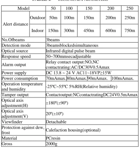
E. Technical Parameters
Following Table I shows technical parameters of infrared sensor required in proposed application.
TABLE I. TECHNICAL PARAMETERS
Model 50 100 150 200 250
Alert distance
Outdoor 50m 100m 150m 200m 250m
Indoor 150m 300m 450m 600m 750m
No.Ofbeams 3beams
Detection mode 3beamsblockedsimultaneous Optical source Infrared digital pulse beam Response speed 50~700mmsecadjustable
Alarm output Relay contact output:NO,NC contactrating:AC/DC30V0.5Amax Power supply DC 13.8 ~ 24 V AC11~18VP≥15W
Power consumption 70mAmax. 80mAmax. 90mAmax. 100mAmax. Operation temperature
and humidity -25ºC~55ºC 5%RH(Relative humidity) Tamper output Contactoutput:NCcontactratingDC24V0.5mAmax Optical axis
adjustment(H) ±180º(±90º) Optical axis
adjustment(V) 20º(±10º) Viewfinder Detachable Protection against dew,
frost Calefaction housing(optional) Material PCresin
Gross 2000g
F. Beam Alignment
Voltage test method:
Remove the cover and connect power.
Adjust the beam frequency of transmitter and receiver to the same channel.
Adjust the vertical adjusting wheel, the signal strength indicator will light up step by step, adjust until level 5 or higher indicator lights up if not adjust it again.
Insert the test pen in to the test hole (please note the+,-polarity).
First adjust the horizontal angle until the test hole voltage output maximize. Then adjust the until the test hole voltage output maximize. Then adjust the vertical angle by the same way.
G. Wiring Connections
Table II, III, IV, V & VI show detail connections required for transmitters and receivers used in application development.
TABLE II. TRANSMITTER WIRING CONNECTIONS.
Transmitter
Terminalnos. Connectiondetails
1. 12VSupply
2. Gnd
3 & 4 Noconnection
TABLE III. RECEIVER I FOR ALARM GENERATING HOOTER
CONNECTIONS
Receiver I(For alarm generating by hooter)
Terminalnos. Connectiondetails
1. 12Vsupply
2,3 Gnd
5. Trigger of Timercircuit
4,6 & 7 No.connection
TABLE IV. RECEIVER II FOR ALARM GENERATING HOOTER
CONNECTIONS
Receiver II(For alarm generating by hooter)
Terminalnos. Connectiondetails
1. 12Vsupply
2&3 Gnd
4,6&7 Noconnection
5. Connectedto5thterminalofReceiverI
Receiver I (RFID) A tag will be connected in place of hooter and timer circuit.
TABLE V. RECEIVER I FOR RFIDCONNECTION.
Terminalnos. Connectiondetails
1. 12VSupply
2,3&4 Gnd
5,6 & 7 Noconnection
Receiver II (RFID) A tag will be connected in place of hooter and timer circuit.
TABLE VI. RECEIVER II FOR RFID CONNECTION.
Terminalnos. Connectiondetails
1. 12VSupply
2. Gnd
3. ToTag
4. Connectedto4thterminalofReceiverI
5,6 & 7 Noconnection
H. Connectors Used for RFID:
Figure 2. Fivepin, three pin&two pin round connector.
TABLE VII.CONNECTORS USED FOR RFID
Pinno. Fortag ForDCoutput ForACinput
1 Gnd Gnd Neutral
2 Supply No connection Phase
3 No connection Supply
4 Receiver terminal
5 Receiver terminal
1) For alarm sound emitter by hooter:
Figure 3. Fourpin, three pin &two pin connector.
TABLE VIII. TIMER CIRCUIT CONNECTIONS
For timer circuit
Pinno
. Fortimercircuit
ForDCpowersuppl y
ForACinpu t
1 Gnd Gnd Phase
2 Supplyfortimer Noconnection Neutral
3 Noconnection Supplyforrelay
4 Connectedto5
thterminalofI R
III. WIRELESS CAMERA
This is a great Wireless and Wired IP monitoring system and it works with both PC by simply connecting with LAN cable or through network router. The camera also process span (270°) and tilt (120°) remote rotation through browser. The web interface has 9 squares (3x3screen), 4squares (2x2screen) and single system so that you can connect up to 9 IP cameras for system monitoring.
This IP camera has motion detection, alarm function. Moreover, the camera has built-in infra-red LED with night vision function at night. You can view and record the video or picture into PC and the file can be viewed by standard window media player. You can even do remote monitoring on Internet or Mobile Phone (can connect Internet) with provided software.
A. Some of the Camera Features
Day/night vision mode.
480Kpixels colour digital CMOS sensor, 0.3Lux low lux illumination.
installation and operation Remote control pan & tilt camera–PAN:270° and Tilt:120°.
Two way audio monitoring.
Nine squares system/Quadra system/single system screen monitor-Connecting up to 9 IP cameras for system monitoring.
Motion detection–Automatically captures moving objects, and send captured video or snapshot file to your assigned email address or FTP.
Alarmfunction–
Motiondetectionalarm,andexternalinput/outputalarm ssuchasPIRmotiondetector,smokedetector,gasdetect oretc.
Viewing/Recording-Clear user interface to view real-time pictures. Even when you leave for a while, IP camera will record the pictures and transfer files to your PC. Files will be saved in the form of standard windows media, suitable for extensive application program.
Easy installation-IP CAMERA is an independent system, with built-in CPU and picture decoder. Just one power adapter and LAN connection can make it work.
Multi form protocols-TCP/IP network protocol, SMTP protocol, HTTP protocol and other protocols related to internet.
Simple configuration-With standard web browser in administrator interface.
Administrator can control and manage IP Camera by LAN or Internet.
Dynamic Monitoring–Capturing any tiny pictures and sends to your mailbox. IP camera will automatically compare the two continuous pictures and find out the changes caused by moving. Following Fig. 4 shows camera can also take part in a multi camera network application.
Figure 4. Multi camera network application.
IV. FUNCTIONING OF SOFTWARE INVOLVED
Let us look at the proto type of the software that has to be developed for integration of the components and efficient working of the system. The central server is always highly secured and the administrator can access it with a user-id and password which has to be entered in
the login page. After logging in a map of the entire premises guarded with the IR sensors is displayed in a console and the beacons indicate the intrusion. Each beacon represents a unique position, which is equipped with the entire arrangement. Red indicates intrusion and Green indicates no intrusion. The current or real time view of the position scan be monitored by clicking on the irrespective positions in the interactive map. [5]
In case of intrusion, the beacon turns red and on clicking on the position, the exact details like date and time of intrusion, the related videos and snapshots of the intrusion can be obtained. After the intrusion, the dual radio sends the SMS and MMS to the central server. Upon receiving the information, a separate window pops-up with the provision of sending the MMS to the user/owner of the premises manually. A SMS is also sent to the owner besides the central server.
In case of malfunctioning or failure of any of the components, a pop up is automatically generated from the respective positions with the details of the faults and a reminder is set until their repair or replacement is accomplished. [6]
V.PROPOSED SYSTEM WORKING PRINCIPLE
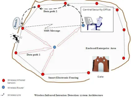
The perimeter of the boundary wall is segmented into multiple straight-line segments of length <=200 meters. The following Fig. 5 illustrates ten-segment intrusion detection system. Then, each segment is protected against intrusion using a pair of Wireless Intrusion Detection units. There is no limit to the number of segments that can be used to protect a long boundary wall.
Suppose there is a ten-segment intrusion detection system as shown in Fig. 1 it includes ten Wireless Intrusion Detection units, wireless routers for data communication to a remote computer (central security office) and software at central security office for visualization, report generation and data analysis.[7]
Figure 5. Wireless infrared intrusion detection systemschematic
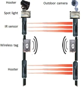
for alert generation. Additionally, an outdoor camera may be used for each segment to capture snapshots of the event as soon as any intrusion is detected. Each segment can realize a straight-line fencing of length <=200 meters. Each mounting unit (Tx and Rx for IR) will also include a wireless tag to send the intrusion signal wirelessly to control station and hooter, spot light and (an optional) camera for alert generation. [8]
Figure 6. Proposed wireless intrusion detection system.
Central security office is nothing but remote control station with wireless receiver for getting intrusion location information from wireless tag attached to the intrusion detection unit. GSM/GPRS modem is used to send automatic SMS to preset mobile numbers and software to capture snap-shots of affected area. [9]
VI. CONCLUSION AND FUTURE WORK
This proposal has resulted in the development of an effective, low-cost wireless intrusion detection system. The device and the RFID tags used to instrument the environment are inconspicuous and low cost. As soon as the routing and the communication between control station and user works, new opportunities may arise to make the system viable for people with special requirements. Future work will be solving problem of false alarm. [10]
REFERENCES
[1] S. Roy, Anurag D, and S. Bandyopadhyay, "Testbed implementation of a pollution monitoring system using wireless sensor network for the protection of public spaces," International Journal of Business Data Communications and Networking, vol. 5, no. 4, Oct-Dec, 2009.
[2] S. Bandyopadhyay, S. Roy, and M. Pal, “Ubiquitous computing for improving industrial safety and security management,” in Proc. Ubicomp-India 2010, C-DAC, Chenai, 29th & 30th January 2010. [3] S. Roy, S. Bandyopadhyay, M. Das, S. Batabyal, and S. Pal, "Real
time traffic congestion detection and management using active RFID and GSM technology," presented at the 2010 International Conference on Intelligent Transport Systems Telecommunications, Kyoto, Japan, 9-11 November 2010.
[4] K. Rajawat, A. Cano, and G. B. Giannakis, “Network-compressive coding for wireless sensors with correlated data,” IEEE Transactions on Wireless Communications, vol. 11, no. 12, December 2012.
[5] G. J. Chen, V. Dwyer, I. Krikidis, J. S. Thompson, S. McLaughlin, and J. Chambers, “Relay selection for secure cooperative networks with jamming,” IEEE Transactions on Wireless Communications, vol. 11, no. 6, June 2012.
[6] G. Middleton, B. Aazhang, and J. Lilleberg, “A flexible framework for polynomial-time resource allocation in streaming multiflow
wireless networks,” IEEE Transactions on Wireless
Communications, vol. 11, no. 3, March 2012.
[7] J. M. Chung,S. Moon, and M. Kim, “Broadcast scheduling for wireless mesh networks based on transmission demand,” IEEE Transactions on Wireless Communications, vol. 12, no. 2, February 2013.
[8] Wireless Network Security, NIST, Technology Administration US Department of Commerce.
[9] H. Madura, Z. Sikorski, H. Polakowski, and M. Kastek, Institute of Optoelectronics, Military University of Technology, 2 Kaliskiego Str., 00-908 Warsaw.
[10] K. Mandal1, A. Sen, A. Chakraborty, S. Roy, S. Batabyal, and S. Bandyopadhyay, “Road traffic congestion monitoring and measurement using active RFID and GSM technology,”
JayashreeKharat, Assistant Professor in
Department of Electronics Engineering, DKTE’s TEI, Ichalkaranji. Research interest is inVLSIdesign.
PrashantKharat, Assistant Professor in