Wind Mill Shaft Design and Optimization
Using Composite Materials
Saket S.Patil1, Ajitabh Pateriya2, U. M.Mohod3
P.G. Student, Department of Mechanical Engineering, VBKCOE MALKAPUR, Maharashtra, India 1
Assistant Professor, Department of Mechanical Engineering, VBKCOE MALKAPUR, Maharashtra, India 2
Associate Professor, Department of Mechanical Engineering, A.E.C., CHIKHALI, Maharashtra, India3
ABSTRACT:This contribution deals with the possibility of simulation of complex parts made from
polymer-composites with CAD/CAM/CAE software. First part of contribution is aimed on describing the basis of fiber composites and its behavior under load. Main reason of choosing carbon fibersas material for innovative parts depends on low density and high tensile strength. Thus carbon fiber composites are frequently used at automotive and sporting goods production, parts from these industries were selected. Along with this work design of Shaft is done for said application. Second part of work will lead to different studies performed in Simulations and describes the stress and weight comparisons made from Steel, Carbon fiber/Glass Fiber composites. The optimization for weight and strength of the shaft based on Fiber orientations and thickness of fiber’s will be done.
KEYWORDS:FEA,MODAL FEA,NATURAL FREQUENCY,FORCE COMING ON SHAFT ETC.
I. INTRODUCTION
A windmill is a mill that converts the energy of wind into rotational energy by means of vanes called sails or blades. Centuries ago, windmills usually were used to mill grain, pump water, or both. Thus they often were gristmills, wind pumps, or both. The majority of modern windmills take the form of wind turbines used to generate electricity, or wind pumps used to pump water, either for land drainage or to extract groundwater.
II. ESIGNOFSHAFTVALUES
Power = 2000 kW Rotor Speed: 16 rpm Wind speed = 12 m/s
Rotor assembly Weight = 215746.30 N Shaft Material as: 25 CrMo4
Syt= 450 N/mm2 Sut= 700 N/mm2 Tower Height = 80 m (260 feet)
Blade & Hub weight = 22000 kg Nacelle & generator weight = 52000 kg Tower Weight = 125 to 150 tonnes
Rotor Diameter = 88 m (288 feet) Di =250 mmDo=418 mm Torque = 1193.66 x 106 N-mm
Shaft Material as,
Sr.No. Material Syt Sut
1 Steel (25CrMo4)
450 N/mm2
700 N/mm2 2 Carbon epoxy 670
N/mm2
825 N/mm2
III.FINITE ELEMENT ANALYSIS OF SHAFT
3.1 Analysis of existing Shaft
Structural steel/Alloy steel is used as existing materials. By using the existing material the analysis is performed in ANSYS.
3.1.1 Static Structural Analysis
A static analysis calculates the effect of steady loading condition on a structure, while ignoring inertia and damping effects, such as those caused by time varying loads. A static analysis can, however, include steady inertia load (such as gravity and rotational).
Static analysis determines the displacements, stresses, strains, and forces in structures or components caused by loads that do not induce significant inertia and damping effects. Steady loading and response conditions are assumed; that is, the loads and the structure’s response are assumed to vary slowly with respect to time.
3.1.2 Modal Analysis of shaft for finding Natural Frequencies
Modal analysis is used to determine the vibration characteristics (natural frequencies and mode shapes) of a structure or a machine component while it is being designed. It also serves as a starting point for another, more detailed analysis, such as a transient dynamic analysis a harmonic response analysis, or a spectrum analysis. Modal analysis also used to determine the natural frequencies and mode shapes of a structure. The natural frequencies and mode shapes are important parameter in the design of a structure for dynamic loading condition.
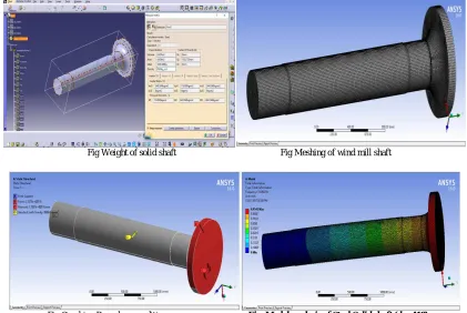
Fig Weight of solid shaft Fig Meshing of wind mill shaft
3.2 Optimization Analysis for Shaft at Different Thicknesses (Hollow) with Carbon Epoxy fiber
Solid shaft is over safe and further can be considering for Hollow shape (for weight reduction). For the same, dimension of hollow shaft is to be determined. Considering various thicknesses and further Analysis of the sameStarting from di/do = 0.6 ,So do = 418 mm, hence di = 250 mm
3.2.1 Property of materials
Material 25CRMO4 Steel carbon
Fiber/Epoxy fibers
Young's Modulus 'E' 210 x 103MPa 70 Gpa
Poisson's ratio 0.3 0.3
Density 7860 kg/m3 1600 kg/m3
yield tensile strength, 450 MPa 670 MPa Ultimate tensile
strength 700 MPa 825 MPa
Fig Weight of shaft (ID 250 mm) Fig Combined boundary condition
3.2.2 Modal analysis of Epoxy hollow shaft
After finalising the suitable thickness modal analysis are done and frequency tabulated in following table
From the static structural analysis of hollow shaft with the carbon fiber/epoxy fiber as a material, it is found out that the ID = 250 mm shows better result, because stress are within limit as compared to allowable stress for the carbon fiber/Epoxy fiber. Carbon fiber/Epoxy fiber has low density and high strength. Selected diameter shows good result as compared to other diameter also the deformation is considerable limit i.e. 13.66 %
Weight of the shaft is to be reducing up to 31.20 % so overall cost is to be minimized.
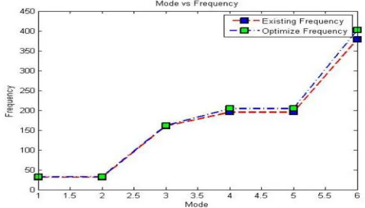
Table Result for Modal Analysis (Existing and Optimized) Table Result Frequency (Existing and Optimized
From results of normal mode analysis, it is seen that the natural frequency of existing design is 31.056 Hz and proposed design is 32.50 Hz. So there is rise in natural frequency of proposed design. Further the second and onwards the frequencies of proposed design are increased compared to existing design. So overall the dynamic performance of the Shaft is being improved.
Trial ID,
mm
Thickness, mm
Stress, MPa
Deformation, mm
Weight, kg
0 Solid -- 244.17 11.139 3338.048
1 230 94 374.75 12.363 2456.32
2 240 89 385.56 12.611 2377.988
3 250 84 409.95 12.903 2296.316
4 260 79 425.49 13.251 2211.31
5 270 74 470.45 13.662 2122.97
Mode Frequency [Hz]
Existing Shaft
Frequency [Hz] Optimized Shaft
1. 31.056 32.50
2. 31.057 32.51
3. 160.49 161.60
4. 195.12 204.16
5. 195.13 204.17
3.2.3 Result Comparison For Existing And Optimized Shaft
Parameters Existing Optimized
Material Steel- 25CrMo4
(Solid)
CarbenFiber/Epoxy fiber (Hollow- ID – 250mm)
Weight 3338.048 kg 2296.316 kg
% Change in Weight Hollow Shaft is 31.20 % lighter than Steel
Stress 244.17 MPa 409.95 MPa
% Change in Stress Hollow Shaft has 40.44 % more Stress than Steel but its within allowable limit
Deformation 11.14 mm 12.903 mm
% Change in Deformation Hollow shaft has 13.66 % More deformation than Steel but it’s not big issue
Table:- Result comparison for existing and optimized shaft
IV.CONCLUSION
4.1 Conclusion
It has been observed that all the stresses were within the allowable limit. Shaft with hollow ID- 250 mm shows safe results.
Hollow shaft at 250 mm ID shows very less weight (31.20 %) compare to solid and hence finally suggested for shaft improvement for weight reduction application.
Hollow shaft at 250 mm ID shows high Stress (40.44 %) and deformation (13.66 %) values compare to steel-25CrMo4 but those are within limit while considering.
REFERENCES
1) Chris J. Burgoyne, Cambridge, UK “Advanced Composites in Civil Engineering in Europe” at Structural Engineering International report 4/99.
2) Branislav Duleba, Frantisek Greskovic“Simulation of Loading the Polymer/Carbon Fiber Composites and Prediction of Safety Factors” at International Journal of Engineering and Innovative Technology (IJEIT) ISSN: 2277-3754, Volume 2, Issue 8, February 2013.
3) Darren A. Baker, Timothy G. Rials“Recent Advances in Low-Cost Carbon Fiber Manufacture from Lignin” at Journal of Applied Polymer
Science DOI: 10.1002/APP.39273, 2013.
5) Patil Deogonda, Vijaykumar N Chalwa “Mechanical Property of Glass Fiber Reinforcement Epoxy Composites” at International Journal of Scientific Engineering and Research (IJSER) ISSN (Online): 2347‐3878 Volume 1 Issue 4, December 2013.
6) H. Kim, H. T. Hahn, E. Bekyarova, E. Oh, G. Lee “Carbon Fiber Composites Reinforced With Carbon Nano materials” at 18th International Conference On Composite Materials.
7) Mark Broderick, Douglas Denton and Michael Shinedling, 0f Daimler Chrysler Corporation and Michael Kiesel, Quantum Composites “Applications of Carbon FiberSmc for the Dodge Viper” Case Study.
8) “Optimum Design and Analysis of a Composite Drive Shaft for an Automobile” Gummadi Sanjay, AkulaJagadeesh Kumar Department of Mechanical Engineering Blekinge Institute of Technology Karlskrona, Sweden 2007.
9) Design And Analysis Of Composite Drive Shaft V. S. Bhajantri, S. C. Bajantri, A. M. Shindolkar, S. S. Amarapure.
10) Wind Turbine - Materials and Manufacturing Fact Sheet Prepared for the Office of Industrial Technologies, US Department of Energy By Princeton Energy Resources International, LLC. Dan Ancona and Jim McVeigh, August 29, 2001.
11) “Testing of highly loaded horizontal axis wind turbines designed for optimum performance” N.A. Ahmed *, R.D. Archer Aerospace Engineering, University of New South Wales, Sydney, NSW 2052, Australia Received 30 November 2000; accepted 6 February 2001. 12) Naresh K, Shankar K, Rao BS, Velmurugan R, “Effect of high strain rate on glass/ carbon/hybrid fiber reinforced epoxy laminated composites”,
Composites Part B (2016), doi:10.1016/j.compositesb.2016.06.007.
13) “Design and Analysis of Composite Drive Shaft” Pankaj K. Hatwar, Dr. R.S. Dalu Government College of Engineering, Mechanical Engineering Department, Amravati, India.
14) Design and Analysis of Horizontal Axis Windmill Turbine Blade, Sowdager Moin Ahmed Assistant Professor, Santhiram Engineering College Andhra Pradesh, India.
15) “Design And Material Optimization Of Wind Turbine Blade” D.L.V. Subrahmanyam, Kuppili Mohan Krishna, Sammala Rajasekhar, Y.DhanaSekhar.
16) “Design & optimization of automotive composite drive shaft” Sumit Dhanwate, Shailesh Pimpale, Swapnil Kulkarni, Rajarsh iShahu College of Engineering, Tathawade, Pune, India.