NON
LINEAR
SEISMIC
ANALYSIS
OF
RIGGING
FRAME
UNDER
HEAVY
TRANSIENT
LOAD
Sohrab Esfandiari1), William Horstman2), Scott Maze2)
1) ENOVA Engineering Services, Walnut Creek, California, USA 2) Pacific Gas & Electric Company, Avila Beach, California, USA
ABSTRACT
Many commercial nuclear plants are currently undertaking major capital improvement projects such as Steam Generator Replacement (SGR), Reactor Head Replacement (RHR), Pressurizer Replacement (PR), or Turbine Rotor Replacement (TRR). Replacement of such heavy equipment typically requires transportation on heavy-duty industrial grade transporter, specially designed for the cargo and the limited purpose. Whilst en-route, the transporter and cargo may have to cross over temporary rigging frames designed and erected to accommodate the desired path. Rigging frames are often temporary structures, and if subject to full seismic load of the heavy transporter and cargo, often require massive design, if conservatively evaluated.
In support of a recent project for Diablo Canyon nuclear power plant undertaking steam generator replacement, this issue had to be considered. A rigging frame was designed and erected to accommodate lifting and movement of the steam generator and the transporter en-route to the containment equipment hatch. Even though the nature of the loading was transient, and probability of seismic event during transient movement of steam generator is very low, but because of high magnitude of the foot-print load, the plant conservatively decided to design the frame for possible seismic loads associated with movement of steam generator.
Simplified and conservative design of the frame imposing large lateral load associated with the inertia of the steam generator and the transporter would produce a large overturning moment at the base of the frame, in turn resulting in large tensile forces on one set of columns counter-resisted by large compressive forces on the opposite set of columns. This in turn would require a massive foundation to be able to resist the large tensile forces. In reality, under seismic inertia, the transporter would tend to slide and/or uplift (due to rocking), thus separate from the surface of the rigging frame. As such, these artificial tensile forces are never exerted on the frame columns, and instead the induced seismic energy is dissipated through sliding and rocking. This also would tend to result in higher compressive forces than what a linear solution would predict for the frame columns, but would make the design of the column footings much simpler and substantially reduced in size. The overall system is analyzed accounting for these geometric non-linearities, in order to ensure seismic stability of the transporter and the cargo, as well as extraction of proper seismic reaction forces, for both evaluations of the structural elements of the rigging frame, as well as the internal design of the attachments of the steam generator to the transporter.
INTRODUCTION
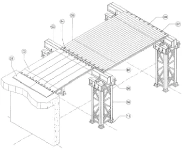
As part of the Steam Generator Replacement Project (SGRP) at DCPP, the transporter carrying the steam generator was lifted from the ground and placed on a steel platform which was erected adjacent to the Auxiliary Building in order for the transporter to move inside the Aux. Building at El. 140’. This frame is referred to as the Rigging platform and comprises of 4 steel towers which were founded at Ground and have a steel deck at El. 140’ which will sit on top of the floor deck at this elevation of the Aux. Building (see Figure 1 for schematic view).
Traditional linear seismic analysis of the frame with the very large mass of the Transporter/SG attached to the frame platform resulted in large uplift force at the tower bases. These large uplift forces in turn dictated a large concrete foundation at the base of the towers. In reality, since the transporter is not attached to the platform, under seismic excitation, it will slide and rock. Under rocking scenario, the transporter may separate from the platform top which means it will not pull the frame with it under tension, but as it slams down, it may exert a higher compressive downwards load onto the platform which in turn has to be carried down by the support towers into the tower foundations. By performing a non-linear seismic analysis of the combined frame supporting the transporter/SG, and by modeling the contact interface between the transporter tires and the frame platform, it became possible to arrive at proper frame reaction forces. This means that the expected reactions at the tower foundations were much less in tension and somewhat higher in compression when compared to results of a linear seismic analysis.
This paper presents the modeling approach, analysis cases, and results for the non-linear seismic analysis of the SGT rigging frame supporting the DCPP Steam Generator mounted on a Transporter.
TECHNICAL APPROACH
The SG/transporter is free to slide and rock along its travel load path as it is being hauled around on top of the frame steel platform, in the event that the friction resistance between the transporter tires and the supporting surface is overcome by the inertia forces imposed by the earthquake. Sliding will take place along both the transverse and the longitudinal directions. Longitudinally, the transporter will roll when the breaks are not engaged. However for stationary scenarios when the transporter breaks are on, longitudinally potential sliding will also take place once friction resistance is overcome.
The sliding and rocking seismic response of the transporter was predicted using a non-linear simplified rigid body representation of the transporter subject to both horizontal and vertical time histories of input motion. The effects of dynamic coupling between the supporting frame and the Transporter/SG were explicitly accounted for by modeling the frame as a supporting structure. This correctly allowed for changes in the input motion at the Transporter/SG level which may happen because of dynamic characteristics of the supporting frame.
The non-linear model simulates the geometric non-linearity inherent in this problem. At the base surface contact of the transporter (tires to supporting steel platform surface) two distinct geometric non-linearities exist:
• Horizontally (both lateral and longitudinal), friction is the only means of resisting lateral motion. Once friction is overcome the transporter begins to slide relative to top of the supporting surface. This non-linear behavior is modeled using friction elements at the base of the transporter.
• Vertically, the transporter is free to separate from the supporting surface in the “up” direction due to potential rocking and free-flight modes of response. However in the “down” direction, the supporting surface will act as a restraint to the transporter. This geometric non-linear behavior was modeled using gap/contact elements at the base. In addition, vertical dashpots were placed under the gap element to absorb the energy dissipated due to contact of the transporter on the supporting surface. Also vertical springs were placed under the gap element to represent the vertical stiffness of the transporter support mechanism, once contact with the supporting frame was made.
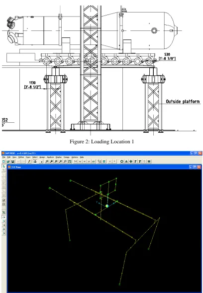
In addition the model exhibits 2 additional geometric non-linear which are the contact between the SG and the transporter (modeled by gap/friction elements) as well as the grommet wires (modeled by tension-only elements) which hold the SG on top of the transporter saddles. The supporting frame and platform are essentially linear structural elements. The towers were modeled using beam elements of equivalent stiffness as provided by the manufacturer. All analyses were performed using the SAP2000 Non-linear computer program (Ref. 1), using the Fast Nonlinear Analysis (FNA) approach.
Figure 2: Loading Location 1
RESULTS
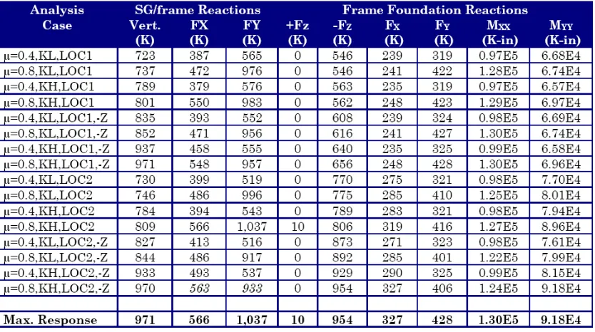
Table 1 shows the sliding and uplift response as well as resulting maximum accelerations at the CG of the transporter/SG for various analyses cases. Table 2 summarizes peak reactions forces at the interface of transporter and SG used for design of attachments of SG on the transporter. This Table also shows the peak reactions at the base of the rigging frame.
Table 1: Summary of Sliding and Uplift Diaplacements
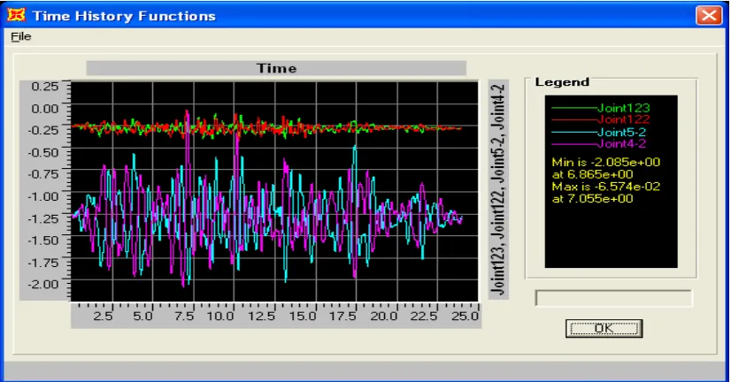
Figure 4 shows the uplift displacement TH for the transpoter/SG and with respect to top of the rigging frame. For uplift displacement, an uplift is noted when the vertical displacements of nodes 4 & 5 cross-over those of nodes 122 & 123 (corresponding nodes at top of RoRoRamp frame location). This is demonstrated in Figure 4. For majority of cases where no uplift is reported, this cross-over does not happen.
Figure 4: Peak Uplift Displacement, COF = 0.8, KH, LOC2
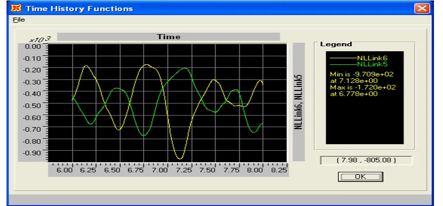
Figure 5 shows the peak reaction force time history, which is for analysis case 8. Figure 6 shows a close up of the reaction force time history between t = 6.0 and t = 8.0 seconds into TH, demonstrating that the peak reaction force does not occur at both transverse sides of transporter simultaneously, and that it alternates between one side and the other, thus showing that peak force is as a result of rocking of the transporter.
Figure 6: Close-up of Peak Vertical Reaction Force at RoRoRamp between T=6.0 and 8.0 Sec. into TH, COF = 0.8, KH, LOC1, -Z
CONCLUSIONS
The following conclusions were reached regarding seismic stability of the transporter carrying the SG on top of the rigging frame subject to design basis seismic event at DCPP. The estimates of sliding displacements were based on a dynamic COF of 0.4 between the transporter tires and the RoRoRamp surface. The rocking analysis was done using a dynamic COF of 0.8 to maximize potential for rocking. These conclusions were based on two bounding values of tire stiffness (KL and KH), and 2 transporter locations on top of the frame (Location 1 and Location 2). The conclusions were:
• The transporter is not susceptible to excessive rigid body rocking. Max. predicted uplift displacement associated with rocking of the SG is 0.36” corresponding to the upper bound vertical stiffness KH. This corresponds to a rocking angle of 0.67 degrees, which is considered negligible.
• The upper bound estimation of max. sliding displacement was conservatively estimated as 7.5” laterally and 13.2” longitudinally which was the highest individual case response multiplied by a safety factor of 3. This conservative factor of 3 was applied in lieu of not performing 4 sets of statistically independent TH analyses as required by SRP (Ref. 2).
• The peak acceleration response at CG of SG was calculated as 0.76g (lateral or X), 1.40g (longitudinal or Y), and 0.63g (vertical).
• The foundations at the 4 towers hardly see any vertical uplift load as expected. This is because of the rocking response of transporter/SG and potential for separation from the platform top. Peak uplift foundation load is calculated as 10 Kips. Peak compressive foundation load is reported as 954 Kips (which includes gravity).
PRACTICAL APPLICATIONS
By performing non-linear seismic analysis of a heavy object (such as a transporter carrying a heavy load) which is physically not attached to the supporting structure, one can predict proper reactions on the supporting structure, which often means eliminating the tension reaction forces (as the unanchored object is free to separate from the supporting structure), but somewhat higher compressive force associated with slam-down of the object during the rocking phenomenon. In addition, these kinds of analyses can properly predict the sliding and uplift displacement of the unanchored object, whereas traditional energy balance approach, may predict instability.
REFERENCES
1. Computers & Structures, Inc., SAP2000 Analysis Reference Manual.