Smart Food Ordering System in Restaurants
Komal Patil1 , Rohini Shinde2 , Jyoti Sargar3, Prof. Raut D.M4
U.G. Student, Department of Electronics and Telecommunication Engineering, FTC COER,
Sangola, Maharashtra, India1,2,3
Asst. Professor, Department of Electronics and Telecommunication Engineering, FTC, COER
Sangola, Maharashtra, India4
ABSTRACT: Now a days , we have automation in every field .The food industries has good prospects ,especially the
restaurants plays the important role , thus we have designed the system for simplicity. Now a days in restaurants , the waiter takes the order from customer then places the order to the kitchen and then billing is done. This whole process is very time consuming. So we can use here “Digital menu ordering system.” Here we are using PIC microcontroller, RF module for data transmission and LCD display for the displaying the menu. Advanced menu ordering system allows the user or customer to select any item by their choice and that order will be transferred to the chef side for further processing and that ordered item will be given to that customer. We shall provide each table with a microcontroller based order placement unit. The menu items, their cost and information will be display on the LCD display.
KEYWORDS:PIC microcontroller, LCD display, Keypad, RF module.
I. INTRODUCTION
In the food industry, the development is getting strong day by day where the people mostly prefer the food in the restaurants because of their fast and running life. The hotel management is also improving the quality of service in the form of hospitality in receiving the customers as well as hygienic maintenance in food supply.
The older methods of ordering the menu in the hotel industry includes more human efforts for getting the order from customer by giving them the printed menu cards on their table. The menu card and ordering system using LCD display for menu and display will get a great response from hotels. The RF module will provide accurate data transmission. This system can be used by all range of hotels and restaurants as its cost of installation is cheaper due to the use of RF module which is used as a wireless interface and LCD and keypad as customer interface.
II.RELATEDWORK
1. BLOCK DIAGRAM:
a) TRANSMITTER SECTION:
A transmitter section consist of PIC microcontroller, LCD display , keypad along with RF module.
The transmitter section will be placed on each table .The RF module makes the communication between the system at the table and the system at the kitchen section.
The RF module covers up to 500 feet distance. According to user’s requirement, they will select the menu item which is displayed on the LCD display by using the keypad.
Fig 1: Transmitter section
b) RECEIVER SECTION:
At the receiver side (kitchen side), we can use a PC and the RF module. The order which is placed from the customer will be display on the PC. The RF module at the receiver side is used for the serial data transmission.
We can use here the ‘Flash Magic’ software for displaying the customer’s order on the PC. The result will be display according to the table number, price of each food item and quantity of food item.
Fig 2: Receiver section
III.HARDWAREDESCRIPTION
1. MICROCONTROLLER:
FEATURES:
1. 256 bytes EEPROM memory. Data can be written more than 1,000,000 times. 2. 368 bytes RAM memory.
3. A/D converter.14 channels 4. 3 independent timers/counters. 5. Watchdog timer.
6. Analogue comparator module with two analogue comparators. 7. PWM output steering control.
8. Enhanced USART module support RS-485, RS-232 and LIN2.0.
Fig 3 : PIC Microcontroller
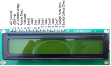
2. LCD DISPLAY:
A 16x2 LCD display is used which consist of 8 bit data lines (D0 – D7) used to send commands and data. It is used in 4 bit mode (D4 – D7).
The roll of LCD is to just display the order of food item which is placed by the customer. For this we use RS =1 and R/W =0 to send data and send high to low pulse to Enable pin
Fig 4: LCD Display
3. KEYPAD:
Scanning a Matrix Keypad:
There are many methods depending on how you connect your keypad to your controller but the basic logic is same. We make the columns as I/P and we drive the rows making then 0/P this whole procedure of reading the keyboard is called scanning. In order to detect which key is pressed from the matrixw we make row lines low one and read he columns. Let’s say we first make row one, then column give low and then read the columns. If any of the key in row one is passed will make the corresponding column as low i.e. if second key is pressed in row one, then column two give low. So we come to know that key two of row one is pressed. This is how scanning is done. So to scan the keypad completely, we need to make rows low one by one and read the columns. If any of the button is pressed in a row, it will take a corresponding column to a low state which tells us that a key is pressed in that row. If button 1 of a row is pressed then column 1 will become low, if button 2 then column 2.
Fig 5: Matrix Keypad
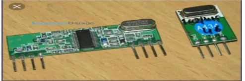
4. RF MODULE:
The RF module operates at the Radio Frequency. The corresponding frequency range varies between 30 KHZ and 300 GHZ. The RF module employs Amplitude Shift Keying (ASK) with transmitter/receiver (Tx/Rx) pair operating at 433 MHZ. The transmitter module takes serial input and transmits these signals through RF. The transmitted signals are received by the receiver module placed away from the source of transmission. The RF signals are transmitted at a particular frequency and a baud rate. A receiver can receive these signals only if it is configured for that frequency. The RF transmitter works at a voltage of 3V-12V and RF receiver works at 5V DC. The working current for RF transmitter is max 40 mA and current for RF receiver is 5.5 mA max.
IV.EXPERIMENTALRESULT
Figures shows the results of Smart food ordering system in restaurants. As shown in fig.(a), customer have to enter their respective table number. The menu will be displayed on the LCD as shown in fig.(b). After completing the customer’s order, the total bill will be displayed on the LCD as shown in fig.(c).
The receiver side is shown in fig.(d). The information like table number, ordered food item, its quantity and total bill will be displayed on the PC. Fig.(e) shows the transmitter side which is placed on each table in the restaurant.
Fig. (a) Fig.(b)
Fig.(c) Fig.(d)
V. CONCLUSION
The implemented system of restaurant menu ordering system is a modern and smart solution for menu ordering methods in any kind of restaurant. The system will reduce the manual efforts and also give more accuracy. It is also a low cost alternative to be used by middle and low level restaurants also. The ordering terminal has the advantages of simple structure, stable operation, low power consumption and friendly interface.
REFERENCES
[1] Prema.G, Vijitha.S, “Smart Food Ordering System in Restaurants”, SSRG International Journal of Electronics and Communication Engineering, special Issue, pp.59-62, 2017
[2] Mr.Devidas Chikle ,”Zigbee based hotel menu card and Ordering System”, International Journal of Technical Research and Applications, Special Issue 39 (KCCEMSR) ,pp.12-15, 2016.
[3] Prof. Anisha Cotta, “Smart Restaurant Menu Ordering System”, International Journal of Science Technology and Engineering ( IJSTE ) , Vol No.2, Issue No.9, pp.176-180, 2016.
[4] B. Shabari, B. Ashok Nayak, “Zigbee Based E-menu Ordering System.”, International Journal of Advanced Technology in Engineering and Science , Vol No.3, Issue No.8, pp. 50-54, 2015.
[5] Prof. Sagar Soitkar, Prof. Ashish harbe, Prof. Vivek Landge, “Touch Screen Based Digital Menu Ordering System Using AVR”, International Journal Of Advanced Research in Science and Engineering –Vol No.3,Issue No.4 ,pp.14-20, 2014