658
MODELING AND SIMULATION OF A MICROGRID TESTBED USING
PHOTOVOLTAIC AND BATTERY BASED POWER GENERATION
Alias Khamis
1Mohamed
2H. Shareef
3A. Ayob
4ABSTRACT
Microgrid is a part of the power distribution system which uses renewable energy based of power
generation connected to the grid system. Multi energy power generation is composed of renewable
energy systems including photovoltaic, wind turbine, energy storage and local loads. Testbed of a
microgrid system is the technique to ensure stable operation during faults and various network
disturbances in grid and islanding connected mode. In this paper the microgrid using renewable
energy consist of a 3 kW photovoltaic, with 30 pieces of 12V for 100Ah battery bank, DC/DC
converter, charge controller for battery, single phase DC/AC inverter and various loads (resistor,
capacitor, inductor) are develop. The AC buses 240V voltage include with isolation transformer to
simulate the grid voltage level by Matlab/Simulink software.
Key Words:
Battery Storage, Inverter, Microgrid, Photovoltaic, Matlab/Simulink.INTRODUCTION
Nowadays, microgid technology using renewable energy based on distributed power generation
system combined with power electronic system will produce the concept of future network
technologies [A.A. Salam, 2008]. The integration of renewable energy sources and energy storage
systems has been one of the new trends in power electronic technologies [seul-ki kim, 2008]. The
main advantages of microgrid development are providing good solution to supply power in case of
an emergency and power outage during power interruption in the main grid. Microgrids comprise
1 Department of Electrical, Electronics and System Engineering National University of Malaysia, Malaysia 2 Department of Electrical, Electronics and System Engineering National University of Malaysia, Malaysia 3 Department of Electrical, Electronics and System Engineering National University of Malaysia, Malaysia 4 Department of Electrical, Electronics and System Engineering National University of Malaysia, Malaysia
Journal of Asian Scientific Research
659
low voltage distribution system with distributed energy resources, such as photovoltaic power
system and wind turbines, together with storage device [F. D Kanellos, 2005].
Currently, Photovoltaic generators are designed in order to generate a maximum power to the grid.
Because of the stochastic nature of the PV power output, large developments of grid connected PV
systems involve large fluctuations of the frequency, power and voltage in the grid [Hicham
Fakham, 2011]. However, the disadvantage is that PV generation is intermittent, depending upon
weather condition. Thus, the MPPT makes the PV system providing its maximum power and that
energy storage element is necessary to help get stable and reliable power from PV system for both
loads and utility grid, and thus improve both steady and dynamic behaviours of the whole
generation system [M. Makhlouf, 2012]. Because of its low cost and high efficiency, the battery
can be integrate into PV generation system which can more stable and reliable.
In this paper, microgrid testbed using renewable energy based power generation system which is
composed of PV array, battery, power electronic converters, filter, controllers, local loads and
utility grid as shown in Figure 1. The paper discusses the detailed modelling of grid connected
PV/Battery generation system. PV array is connected to the utility grid by a boost converter to
optimize the PV output and DC/AC inverter to convert the DC output voltage of the solar modules
into the AC system. Meanwhile, the battery is connected to the common DC bus via a charge
controller to support a stable voltage from PV. The proposed model of the entire components and
control system are all simulated under Matlab/Simulink software. All simulation results have
verified the validity of the models and effectiveness of control method.
Figure-1. Configuration of the microgrid tesbed using PV and battery based power generation.
MICROGRID SYSTEM MODELING
Photovoltaic (Pv) Model
In this project the PV system is modeling based on the equivalent circuit model which has already
state in theory section. The photocurrent generated when the sunlight hits the solar cell can be
represented with a current source and the P-N transition area of the solar cell can be represented
with a diode. The shunt and series resistances represent the losses due to the body of the
660
The electrical model of the PV system was simulated in Matlab/Simulink with an equivalent circuit
model based on the PV model of Figure 2 and Figure 3. The circuit model is using one current
source and two resistors Rs and Rp. The value of the model current Im is calculated by the
computational block that has V, I, and Ipv as inputs. All the input parameters were developed by
using mathematical function that will supplying the information to the PV model circuit based on
the mathematical calculation.
Figure-2. PV system model circuit with a controlled current source, equivalent resistors, and the
equation of the model current .
Figure-3. Equivalent model of PV system in Matlab Simulink with input and output port that
connect to outside of subsystem.
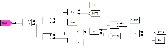
In order to create the input supply or model current , to the equivalent circuit of PV, firstly the
saturation current of was developed. This is done by using the following equation of 1, 2 and
also with the selected parameters. Then the mathematical model of Io was developed in
Matlab/Simulink as shown in Figure 4.
(1)
661 Figure-4. Mathematical model of Io
Then the light generated current was developed by using equation 3 with the selected
parameters. Then the mathematical model of was developed in Matlab simulink as shown in
Figure 5.
(3)
Figure-5. Mathematical model of .
Finally both parameters of and , also with the selected parameter were inserted in equation of
4 in order to obtain the input supply of Im. Then the mathematical model of was developed in
Matlab/Simulink as shown in Figure 6.
(4)
Figure-6. Mathematical model of Buck converter model
In this type of dc converter, the circuit modeling was firstly developed. The buck converter circuit
is shown in Figure 7. Then the main parameter such as input and output voltage, inductance value,
662 Figure-7. Buck converter topology
Duty ratio D, with desired output voltage and voltage input
(5)
Inductance value, L:
(6)
Let the inductor to be 25% larger than the minimum to ensure the inductor current is continuous.
(7)
Then the capacitor was selected by using this equation and the output voltage ripple is not
exceeding 5 percent,
(8)
Battery Model
The battery block implements a generic dynamic model parameterized to represent most popular
types of rechargeable batteries.
The equivalent circuit of the battery is shown below:
663
Lead acid model for discharge model with selected parameter was inserted in equation 9. While for
charge model with selected parameter was inserted in equation 10.
Discharge model (i* > 0)
(9)
Charge Model (i* < 0)
(10)
Inverter Model
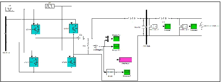
Figure 9 shows outputs from PV and battery connect to inverter, filter and grid system.
Figure- 9. Inverter connects to filter and grid system.
Single phase inverters are used the DC output voltage of the PV array into AC voltage to be
connected to the electric utility grid. The single phase full bridge voltage source inverter circuit
configuration shown in Figure 9. It is composed of a DC voltage source (PV array) an input
decoupling capacitor and four power switching blocks. C is used to filter the noise on the DC bus.
After the inverter an LC harmonics filter is used to eliminate the high frequencies in the output
inverter voltage. Each block of the switching blocks consists of a semiconductor switch (IGBT)
and anti parallel diode. To create proper gating signals for switches, pulse with modulation is used.
The functions of PWM are the control output voltage amplitude and fundamental frequency.
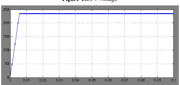
RESULT AND DISCUSSION
Figure 10 shows the output voltage from PV as a 240V DC voltage. Each solar panel with 9.6V
664 Figure-10. PV voltage
For maintaining supply from PV, battery storage support by charge and discharge the system.
Figure 11 shows output from battery 12V for 30 pieces connected in series and the state of charge.
Figure-11. Battery voltage and state of charge
Figure 12 shows output voltage buck converter in DC volts. Here the voltage from PV 240V are
fluctuated and buck converter are used to get pure DC voltage.
665
Figure 13 shows output voltage from inverter before filter in square curve. Here the voltage from
DC converter 240V connected to inverter change to AC voltage.
Figure-13. Outputs from inverter voltage before filters
Figure 14 shows output from inverter after filter in sine wave. The inverter works with a pulse
width modulation technique. The output voltage of filter is shown as pure sine wave with almost no
harmonic content.
Figure-14. Outputs from inverter voltage after filters
CONCLUSION
In this paper the mathematical model of al system components was introduced in order to
investigate the dynamic behavior of each system. Also the proposed control technique of the
system was presented. This includes On/Off switch control of the system modes of operation and
inverter control. The proposed system components implemented in Matlab/Simulink environment
and interface with SimPowerSystem toolbox. The dynamic behavior of each subsystem is
investigated showing the interaction between different components of grid connected PV system.
Renewable energy based power generation as a photovoltaic (PV) with battery storage for
666
consider the outputs and effectiveness of inverter. Most of the results can be used for develop a
small scale microgrid system for practical applications.
REFERENCES
A.A.Salam, A.Mohamed, M.A.Hannan (2008) "Technical Challenges on Microgrid" ARPN
Journal of Engineering and Applied Sciences, Vol. 3, No. 6, pp. 64-69.
Seul-Ki, Kim, Jin-Hong Jeon, Chang-Hee Cho, Jong-Bo Ahn, Sae-Hyuk Kwon (2008)
"Dynamic Modeling and Control of a Grid-Connected Hybrid Generation System with Versatile
Power Transfer" IEEE Transaction on Indsutrial Electronics, Vol. 55, No. 4, pp.1677-1688.
F. D. Kanellos, A. I. Tsouchnikas and N. D. Hatziargyriou (2005) "Micro-Grid Simulation
during Grid-Connected and Islanded Modes of Operation" International Conference on Power
Systems Transients (PPST05) in Motreal Canada.
Hicham Fackham, Di Lu, Bruno Francois (2011) "Power Control Design of a Battery Charger in
a Hybrid Active PV Generator for Load-Folowing Applications" IEEE Transaction on Industrial
Electronics, Vol. 58, No. 1, pp.85-94.
M.Makhlouf, F.Messai, H.Benalla (2012) "Modeling and Simulation of Grid-Connected Hybrid
Photovoltaic/Battery Distributed Generation System" Canadian Journal on Electrical and