R E S E A R C H
Open Access
Beacon routing algorithm in wireless sensor
networks with mobile gateway
Jun Xia
1,2*, Fei Yin
3, Yun Rui
4,2,1, Kai Yu
1, Zhenhong Li
3, Haifeng Wang
3and Zhiyong Bu
1Abstract
In this article, we first propose a reverse sector mechanism and an optimization division mechanism, which can provide enormous energy conservation benefits. Based on these mechanisms, an efficient sensory data collection mechanism over a cellular-WSN integrated network, named beacon routing algorithm, is proposed to
spontaneously renew the local WSN topology according to the position of the UE relative to the location of the beacon cluster under an optimized network division pre-set. Different from the previous studies, beacon routing algorithm achieves the adaptive topology renewal without additional re-clustering overhead. Through performance evaluation, we can implement WSN by making a trade-off between network scale and sector division. Moreover, optimal energy efficiency can be obtained in each divided sub-network; therefore, the WSN lifetime can be increased significantly and the data collection efficiency will be enhanced. Simulation results are presented to show the performance of the proposed algorithm.
Keywords:wireless sensor network (WSN), user equipment (UE), gateway, beacon, routing
1. Introduction
Information sharing between different types of network entities drives the aggregation of heterogeneous net-works. This kind of aggregation provides for example the possibility to exchange information between entities of a local network and a heterogeneous network. A spe-cific scenario for a combination of capabilities of differ-ent networks for information sharing is to use a cellular network element such as a user equipment (UE) or entity as a gateway for local wireless sensor networks (WSNs). That is, elements of a cellular network and a WSN are mixed in order to easily expand the function of each network. With the natural mobility characteris-tic, this new type of multimode UE equipped with WSN module is similar to an enhanced type of mobile sensor node with more energy and flexibility. Since WSN can be deployed easily as less infrastructure and attention are required, the integration of cellular network and WSN seems attractive by combining the sensing part and the connection part in a flexible way, which
expands both networks’ scalability and ubiquitous ser-vice applications.
In this article, we assume a type of isolated sensor net-work and a special sink, eNB, which solve the contradic-tion between the UE and the sink in terms of functionality in convergent scenario. Each UE can play a role of information collector. Since the quantity of UE is huge, it is possible to fully utilize this advantage to col-lect overall sensory data, enhance network transmission efficiency, and increase lifetime of sensor networks. However, as the positions of UEs are random; it is hard for a single UE to collect full information of local WSN with high efficiency. Hence, the traditional topology and routing algorithm used in WSN are hard to meet the collecting efficiency as UEs appear in different positions. For example, it has been suggested to optimize the selection of cluster heads under specific constraints. However, there are still open issues on how to solve problems related to the computation and communica-tion overheads incurred by re-clustering caused by the stochastic nature of UEs.
WSN is subject to a unique set of resource con-straints, such as finite on-board battery power and lim-ited network communication bandwidth. It is well known that communicating 1 bit over the wireless * Correspondence: [email protected]
1
Shanghai Institute of Micro-system and Information Technology (SIMIT), Chinese Academy of Sciences (CAS), Shanghai, China
Full list of author information is available at the end of the article
medium at short ranges consumes far more energy than processing that bit. In conventional routing protocols, sensor nodes make the routing decision via collecting routing information in delivery package and following the rule of specific routing algorithm. Additional routing data exchange between sensor nodes will obviously lead to the network inefficiency and unnecessary energy waste. Thus, we endeavour on turning routing commu-nication procedure into calculation of local sensor node and propose beacon routing algorithm to eliminate communication consumption in routing exchanging process. Sensor nodes in local network can autono-mously make routing decision in an efficient way according to the polling signal containing beacon cluster identification from mobile gateway. Therefore, additional cost of routing message exchange can be saved to increase the network lifetime.
The rest of this article is organized as follows. Section 2 introduces some related studies and discusses the pro-blem. Section 3 presents the beacon routing algorithm in more details, including reverse sector topology method, divided sector optimization, and an implemen-tation example by adopting proposed beacon routing algorithm over a cellular-WSN integrated network. In Section 4, we present our simulation results on the pro-posed algorithm. Finally, we conclude this article in Sec-tion 5.
2. Related studies
In a conventional WSN, sink is a local device for col-lecting data of the whole network. But the data collect-ing efficiency is low for a fixed sink unless a number of sinks are deployed, which actually divides the local net-work into several parts. One sink can communicate with other sinks via internet for the purpose of sharing infor-mation. Perhaps the most profound difference between sensor networks and other types of networks, wired or wireless, comes from the fact that the classical separa-tion of address and content in a packet is no longer viable in the sensor net setting [1,2].
In WSNs, dense networks of distributed communicat-ing sensors can improve signal-to-noise ratio by redu-cing average distances from sensors to the source of signal, or target. Increased energy efficiency in commu-nications is enabled by the multi-hop topology of the network [3]. A solution to the localization problem can specify a set of sensor nodes on a path that gather and combine data as they route the result back to the query-ing node. Conventional protocols, for example floodquery-ing or gossiping-based routing [4], waste energy and band-width to transfer extra and unnecessary copies of data in overlapping areas. In some hierarchical topology based sensor networks, each cluster elects a cluster-head node, and routing is done only among the cluster-heads
(the remaining nodes always route packets through their cluster-heads) [5]. This is advantageous for a variety of reasons, including the possibility of using simpler com-munication protocols within a cluster, recycling of resources (such as frequency assignments) among dis-joint clusters, and saving power. The focus of the exist-ing literature has mostly concentrated on optimizexist-ing the choices of cluster heads to meet some constraints. How-ever, fewer studies have been devoted on how to allevi-ate the computation and communication overheads caused by re-clustering that spurs the development of a gateway node for a WSN.
Mobile sink WSN (MSWSN) is similar to the scenario described in Section 1, since UEs actually serve as mobile sink with random mobility in local WSN. No network information is required as the decision of a sink to decide next sojourn position is random. The movement pattern of a sink does not depend upon work conditions, which may not lead to optimal net-work lifetimes. Random mobility requires continuous sink position updates and route reconstruction, which will increase the transceiver burden of each sensor nodes.
Flooding is an easy routing protocol [6,7], in which each node only needs to broadcast the newly received message to its neighbouring nodes, not requiring topol-ogy records or large amount of analyses. This routing protocol is reliable. Regardless of any changes in the network, data can be transmitted to the sink node in the way of flooding as long as the path between the source node and the sink node exists. But flooding con-sumes much energy, because for each data packet, all nodes in the broadcast domain will receive the packet and forward it to its neighbours. The large amount of power required by flooding causes a prohibitively short network lifetime, which makes it difficult to apply basic flooding protocol to real WSNs.
forward data back to that neighbour if it randomly selects that neighbour. In addition, the gossiping approach does not solve the sink mobility problem.
Data centric routing mechanisms such as directed dif-fusion [8] conduct routing is similar to AODV in ad hoc network, routing request and reply are necessary during the period of path establishment. Path discovery depends on the exchange of inquiring packet among dif-ferent nodes in network. This kind of routing mechan-ism performs better than simple flooding algorithms, but it still relies on basic flooding mechanism during the period of path discovery. Some protocols consider the classical flooding as the basic approach in MSWSN for initializing network and packet delivery. ART Proto-col [9] proposed an adaptive reversal tree-based algo-rithm. A tree directed towards sink assigned temporary root node is created. This is achieved through initial flooding. Source nodes use this tree to direct data reports towards root node which then delivers data to the sink. ART efficient path repair mechanism reduces
sink’s communication overhead but may result in
sub-optimal source to sink path. ALURP and LURP are pro-posed in [10] that include a geographic data dissemination approach. In LURP, sink initially floods its location information plus a virtual circular area (VC) centred on its current position. Then, as long as sink mobility is confined in VC, local broadcast is performed. Exit from VC requires global flooding. Nodes outside VC use geographic routing to route data towards sink. Once packet arrives inside VC, shortest path routing is used on sink updated paths. In ALURP, radius of VC is adapted according to the mobility of the sink. This reduces local broadcast cost. In addition, numbers of global flooding requirements are also reduced as VC size can be dynamically changed.
Complete Graph-based Clustering Algorithm (CGCA) [11] is proposed in a densely deployed sensor network. CGCA divides the network into a few complete graphs; each complete graph independently becomes a cluster. CGCA introduces mobile nodes as gateways and verifies its efficiency in lengthening lifetime of WSN. However, the algorithm imposes some restriction on the behaviour of the mobile gateway, such as roaming around the deployment region, which is unnecessary as more effi-cient and flexible schemes can be proposed.
The discussion about integration of heterogeneous network is very prevalent, but the content about WSN and cellular is scarce. The routing algorithms and topol-ogy control methods described above may be used to solve the problems in each specific scenario, but they cannot be applied in the scenario we suggested in Sec-tion 1 straightforwardly. The tradiSec-tional sink as well as mobile sink are different from UE in terms of
distribution density, transmission capability, mobility randomness, etc.
3. Beacon cluster routing algorithm
Sensor networks extend the existing internet deep into the physical environment. A WSN for a local sensor network may consist of spatially distributed autonomous sensors which are configured to monitor different para-meters, such as physical or environmental conditions like temperature, sound, pressure, movements, concen-trations of specific elements in the air, etc. Each node equipped with one or more sensing devices such as acoustic microphone arrays, video or still cameras, infra-red, seismic, or magnetic sensors. The sensor nodes are further configured to cooperatively pass data through a network to a main location which is also referred to as sink. Also bi-directional communication between the sensor nodes and the sink is possible in order to enable a control of the sensors. WSNs are used, for example, in many industrial and consumer applications, such as industrial process monitoring and control, machine health monitoring, environment and habitat monitoring, healthcare applications, traffic control, etc. The nodes of the WSN may comprise sensor nodes (SNs) and one or more cluster head (CH) nodes. Cluster-head nodes are used as managing nodes when a WSN is divided into one or more clusters containing plural sensor nodes and one cluster head node. The sensor nodes are connected to one (or sometimes several) other sensor nodes, wherein their data are forwarded to a respective cluster head which transmit the aggregated information to the sink. A sensor node has typically several parts: a trans-ceiver with an antenna or connection to an antenna, a microcontroller, an electronic circuit for interfacing with the sensors and an energy source, e.g. a battery or an embedded form of energy harvesting. The topology of a WSN can vary from a simple star shape to a multi-hop mesh network.
The largest design constraint, however, is the limited energy budget of a sensor node together with the requirement of long network runtimes. For instance, having a node continuously powered on drains an AA battery of 3000 mAh in about 4 days [12], which is well below the typically required decade of operation. On the other extreme, even if a node is switched off all the time, inherent current leakages in the battery limits the battery lifetime to 10-15 years in dependency of the operating temperature. This renders network lifetime maximization with battery-powered nodes useless if the lifespan goes beyond this number [13]. In typical sensor applications, the energy consumption is dominated by
the node’s radio consumption. A prominent example of
start-up alone costs the network a third of its battery power [13,14]. Based on these constraints for WSN, high efficient network implementation scheme and data collection under power saving mode is essential for practical applications.
3.1. Assumptions
Generally, the coverage of WSN can be approximately considered as a circular region. For energy efficiency consideration, local sink is inclined to be implemented in the middle of the coverage region. Thus, we can divide the circular region into sectors by slicing the region from the centre of the circle. The following ana-lysis is based on this basic geometry. In this model, we ignore all radio propagation effects such as obstacle or multipath interference, anisotropy or asymmetry of transmission, etc. We assume all nodes have the same
transmission range which is set to be equal to r or
rescaled if necessary. To make it easy for analysis, we further assume the following:
•Each sensor node is homogeneous. Local sensor
net-work is implemented as flat with a unique sink node.
• Index numberi denotes the layer sequence of the
divided sector layer; similarly, index number jdenotes the block sequence of the divided mini sector which represents the divided piece of each layer in the sector.
•The radius of the sector is R, and the transmission range of each sensor node isr.
•The primary energy consumption of each
transmis-sion or reception is approximate to the same basic energy unitEb.
•The vertex angle of sector is set as b; and density of sensor node distributed in the sector is represented byr.
•Energy consumption of the primary mini sector is
specified asEij.
•Chain type network is considered as the basic
net-work model in the following analysis, in which energy
consumption can be represented as Echain, each sensor
node in the chain consumesEsentenergy units to trans-mit data andEreactiveenergy units to receive data.
•Energy consumption of the whole sector is specified asEsec, and for the reverse topology sector case is Ersec.
•Energy consumption of network flow inside the sector
layer is denoted asEintra, which represents the whole
energy consumption of total mini sectors in the same layer.
• Energy consumption of network flow between the
sector layers is denoted as Einter, which represents the energy consumption between each divided layers.
3.2. Reverse sector topology
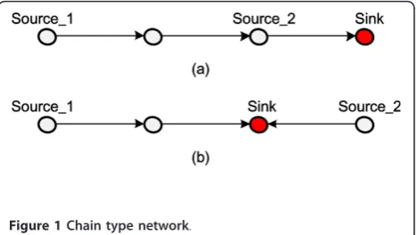
First, we consider a basic chain type network. As illu-strated in Figure 1a, there are two source nodes, one
relay node and one sink on the chain link. Each source node has its own sensory data for dissemination, and the relay node only forwards the data packet originated from source nodes. In terms of source node #2, it also plays the role of relay node. But it can combine the relaying packet with its own packet, and send them together. Thus, the energy consumption during the whole transmission process can be represented as below:
Echain= 3Esent+ 3Ereceive (1)
To make the analysis easier, we assume the transmis-sion power is equal to the receiving power (denoted as Eb) at each node. Then the total energy consumption is 6Eb. If we switch the position of source node #2 and the sink, then recalculate the energy consumption, it is straightforward to find that the total energy consump-tion is the same as above.
Through this simple process, we can find that simply switching the position of sink and source as illustrated in Figure 1b, does not impact the network energy con-servation. But if the energy consumption at sink node side is ignored, which means the sink node is an energy sufficient device, the result will be totally different.
Under this assumption, Echain in Equation (1) can be
modified to 3Esent+ 2Ereceive. Similarly,Echainin switch-ing situation can be modified to 3Esent +Ereceive. Thus, we can find that under the assumption of energy free sink device, simply changing the location and the net-work flow without modify the topology can enhance the network energy efficiency. This also illustrates that the powerful sink node shall be placed closer to the middle position of the network for energy efficiency consideration.
Obviously, decreasing the number of relay hops in the network can efficiently lower the network transmission consumption, which is a well-known principle in net-work optimization. For general analysis, the total energy
consumption ofNnodes in a chain type network can be
concluded as a transmission withN- 1 hops and recep-tion energy consumprecep-tion is
Echain=(N−1) (Esent+Ereceive) (2)
As described in [15], transmit power consumption of sensor node is similar to the receive power consump-tion. Thus, we can still use the prior assumption that
the basic energy consumption unit is Eb. According to
this assumption, the total energy consumption of the chain topology can be calculated as
Echain= 2Eb(N−1) (3)
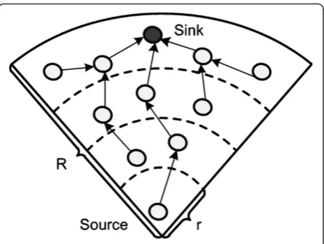
Based on this, each sector in the sector topology is part of the round region and covered by a sink. As shown in Figures 2 and 3, a sector is divided into ⌈R/r⌉ layers according to one-hop transmission range. Layer closer to the sink possesses the higher forwarding bur-den, which is called high layer. The layer far from the sink can be defined as lower layer as its forwarding fre-quency is lower.
As illustrated in Figure 2, the sink node is closer to the vertex of sector. There is a high probability of inter-mediate sensor nodes to keep active status for forward-ing data packets from its child nodes. Intermediate nodes that are closer to the sink consume more energy for forwarding even itself has no sensory data needs to report. In other words, if fewer hops exist in one path from lower layer node to sink or less number of lower layer nodes in the path, forwarding frequency of inter-mediate nodes can be significant lower, as illustrated in Figure 3. In this case, the positions of the sink and source are reversed. The maximum hop in reverse sec-tor can be estimated as max {⌈bR/2r⌉-1, ⌈R/r⌉-1}. Even
b/2≤1, the maximum number of hops in reverse sector
topology is still lower than in the normal case, thus the energy burden of the whole sector in reverse sector topology is also lower than in the normal case.
Below we try to analyse the sector topology energy model. Assume the sensor networks located in the sec-tor are referred as the complete binary tree topology, it is easy to find there are 2i-1chain links flowing to the sink in layer i. Each chain flow possesses (i-1) hops to the sink. Substitute the parameter in Equation (3); we can get the total energy consumption of sector shown in Figure 2 as
Similarly, for the reverse sector topology, we can also represent the network energy consumption with basic chain flow energy model. Then the flow of each layer to the sink may consist of two types of chain flows, which are the inter layer flows and intra layer flows. The inter layer flows include all the vertical chains in Figure 3. To make it easy for calculation, we can stochastically pick a single sensor in each layer to consist the inter layer flow. Thus, the intra layer flows consist of all the chain flows that exist in each single layer and each node prefer transmit data to the node nearby in the same layer. Here the total energy consumption can be estimated as
Ersec=Einter+Eintra
Figure 2sector topology.
The energy consumption in normal case and reverse case can be compared as follows:
Egain=Esec−Ersec network scale here. Thus, inequality (6) can be rewrite as
From inequality (7), it is easy to see that the inequality is consisted by an exponential part and a parabola part. The exponential part actually determines theEgain, with
the increasing of parameter M. Egain tends to be a
monotonic increase function with the growth ofM. As a conclusion, through simple network flow reverse opera-tion, energy cost reservation can be achieved especially in large scale network.
3.3. Divided sector optimization
A well-known wireless network capacity obtained by Gupta and Kumar states that the per node throughput scales as 1√n. In other words, it goes to zeros as the
number of nodes N in a wireless ad hoc network
increases [16]. As the number of nodes increases, every node spends almost all of its time forwarding packets of the other nodes. On the basis of this theory, the scale of local sensor network needs to be maintained in small size in order to guarantee the throughput. On the other hand, if we divide the local sensor network into several parts, the scale of the network is reduced while the throughput of each part is enhanced accordingly. This idea drives us to optimize the division process.
In binary tree topology analysis, we find that it is pos-sible to optimize the local sensor network energy
effi-ciency by making a trade-off between parametersMand
b. Similar to the ordinary sector performance, node den-sity is ignored which may deteriorate network perfor-mance gradually in the reverse sector topology. For this reason, we analyse the general tree topology situation without specific topology. Assuming the sensor node is scattered in the sector region uniformly distributed. The density of the sensor nodes within each square meter is
r. Hence, number of nodes in each layer is
N= (2i−1)
2 βρr
2 (8)
Similar to the above case in binary tree topology, net-work flows in the general sector topology can still be considered as the combination of chain flow originated from each node to the sink. Total energy consumption
of the sector can be calculated as
Esec=
In Equation (9), sector energy consumptionEsecvaries with vertex angleband the nodes densityr. Comparing with Equation (4), the energy consumption of the sector type network is degraded from the exponential growth to the power function growth, which is reasonable in practical scenario. As in the hierarchical network, depth of the network should not be set too large for sensor node lifetime consideration. With the increase of net-work depth, possibility of intermediate nodes out of order rises accordingly. Especially in large scale sensor network, exponential model of energy consumption is obviously unacceptable in practical implementation.
After obtaining the energy consumption in the normal case, we need to estimate the expenditure in reverse case. Similarly, network flows can be categorized as inter sector and intra sector parts, which possess the same meaning as in the binary tree topology analysis, i.e.
Ersec=Einter+Eintra
In Equation (10), if we consider⌈R/r⌉as an
indepen-dent variable of function Ersec, the core part of the
above function can be approximated as a quadratic function. Comparing the energy consumption of normal case and reverse case, the energy saved after the reverse process can be obtained as
Egain=Esec−Ersec
Rewritten the inequality (11) into inequality (12) based on parameterb, we get
In order to find the maximum value of Egain, we take
dEgain
Obviously, we getbwhenEmax_gain achieves the maxi-mum
According to the optimized parameter b, we can get
the max energy gain as
Emax gain=Ebρr2Rr 1
From the above results, the maximum energy gain can be achieved depending on the vertex angle of the divided sector in the circular region. But in practical applications, implementation complexity and expendi-ture cannot be ignored, which may constraint the num-ber of divisions. In these practical cases, we may have to give up the optimal scheme, choose the sub-optimal division number. By dividing Equation (12) with Equa-tion (9), we can get the energy gain efficient funcEqua-tion as follows. we can get the limitation ofEefficient:
lim
R/r→+∞Eefficient= 1−
β
2 (18)
Equation (18) shows that Eefficient increases when b
decreases. In reality, when the scale of the network
grows, smallerb keeps the network more efficient in
terms of energy. In the case that the value ofb is low, which means the reverse section operation will bring more energy conservation for small sector network, the maximum gain of the reverse section cannot be achieved. The trade-off between energy efficiency and energy gain needs to be carefully considered during the practical implementation.
3.4. Beacon routing algorithm implementation
Since we can pre-implement local sensor network according to the optimal division described above, bea-con routing algorithm based on these divided sectors
can be achieved. The beacon routing algorithm is a method of pre-computation based on divided sector model to aid the routing.
We assume the pre-deployed WSN network is seg-mented into multiple sectors without sink and each group has one cluster head to minimize the power con-sumption and increase the WSN lifetime, i.e., most of nodes are in sleep mode and only the cluster heads bea-cons regularly for the purpose of providing basic WSN information. Each cluster with its cluster head is identi-fied by the unique id (namely the beacon cluster id) and each cluster is named as beacon cluster.
We make some important assumptions as follows: •The topology of sensor network is semi-static. •UE as mobile gateway for collecting local sensor net-work data is also semi-static during the data collecting period.
• UE possess the capability to directly notify every
sensor node its up-to-date information via broadcasting. •Cluster division and cluster-head selection are pre-defined during the network implementation period.
Once a UE starts to collect WSN information and access the WSN beacon cluster head, it senses the bea-con transmission by beabea-con cluster head in WSN, col-lects the synchronization information, signal strength as well as local beacon cluster information. Then the UEs report the accessing request to the eNB who selects the UE gateway among UEs nearby the beacon cluster and allocate broadcasting sequence of each UE. The selected UEs trigger the cluster head and awake all WSN nodes in the network, broadcast topology update notification to inform sensor nodes to change their network flow direction. Before a UE updates the location information stored in sensor nodes, it should activate sensor nodes via preamble sample technique [17-19]. Each sensor node with pre-defined routing table changes the net-work flow direction correspondingly. This ensures that the whole WSN information can be collected by the mobile gateway in an efficient way.
Initialization configuration of beacon cluster is essen-tial for the local sensor network. Once an eNB or UE needs to collect WSN information, some UEs will be selected to serve as mobile gateways. Figure 4 shows a WSN segmented into six groups with six cluster heads as an example.
number and the responding relay node towards the spe-cified beacon cluster. Routing table of node #0 in Figure 4 is illustrated in Table 1.
Table 1 is a common routing table with the same function as traditional routing methods. In practical sce-narios, several UEs can appear near different cluster head of beacon cluster simultaneously. Obviously, this simple routing table cannot deal with the situation any-more. Some modification is necessary for the initializa-tion routing table. Thus, we present a conversion algorithm for converting the rough routing table to a routing table based on beacon cluster combination.
After the convert process, each node in the sensor network can get its own routing table according to the beacon cluster. Thus, each sensor nodes have its pre-defined routing table with different network flow direc-tions for different destination. Sensor nodes maintain in the idle mode, and only the cluster head beacons regu-larly for the purpose of minimizing power consumption. Using the conversion algorithm, routing table of node
#0 is calculated and shown in Figure 4. From the new routing table, each sensor node can decide the dissemi-nation direction according to the priority and set of bea-con cluster activated by the UE. This means each sensor nodes can make the routing decision independently.
In order to explain the beacon routing algorithm explicitly, we illustrate three basic scenarios according to the scenario shown in Figure 4. Here, we call the UE as a mobile gateway in local WSN. In Figure 5a, only one mobile gateway accesses beacon cluster #2 for data collection. After the gateway obtains the permission from eNB to collect local network information, it broad-casts a signal to awake the sleeping sensor nodes. The awakened sensor nodes keep listening for the following broadcasting message about beacon cluster ID from the gateway. As illustrated in Figure 5a, node #0 receives notification about beacon cluster #2, and then it checks its local routing table as shown in Table 2. According to the local routing table of node #0, with the highest priority, node #0 selects node #1 as its next hop and starts the data dissemination.
After data collection, mobile gateway depicted in Fig-ure 5a leaves the sensor fields. Meanwhile, four new mobile gateways appear to collect data. In Figure 5b, there are four gateways in network; node #0 receives ID notification about beacon cluster #1, beacon cluster #3, beacon cluster #5 and beacon cluster #6 from mobile gateway. It then checks the routing table in Table 2. As the beacon notification of cluster #2 has expired, the second priority in Table 2 (i.e. priority 4) guides node #0 to change its traffic flow direction to node #2. In this
Figure 4Optimal segmented beacon cluster.
Table 1 Routing table initialization at node #0 after flooding procedure
Beacon cluster ID Last hop Hop count
Cluster #1 NN #3 6
Cluster #2 NN #1 2
Cluster #3 NN #2 4
Cluster #4 NN #2 8
Cluster #5 NN #3 11
routing switching process, routing information interac-tion among sensor nodes is unnecessary since each sen-sor node can choose the efficient dissemination direction independently according to the beacon signal from mobile gateway. In Figure 5c, each beacon cluster head has a corresponding gateway, node #0 selects node #1 as its next hop according the cluster set with highest priority in Table 2. Furthermore, data collection effi-ciency is enhanced with more mobile gateways.
Based on the implementation procedure described above, information collection process in the convergent network combined with cellular and WSN can be described as follows: Once an eNB wants to collect specific WSN information, it broadcasts its request with the related WSN identity to the UEs nearby. The UEs equipped with WSN module will overhear the periodic beacon signals from cluster heads in WSN. Then the UEs extract cluster ID from beacon signal and report to the eNB. The eNB selects and notifies proper UEs as mobile gateways for data collection. Those selected UEs awake all the sensor nodes in local network via broadcasting. During the broadcasting per-iod, the selected UEs as mobile gateways broadcast the beacon cluster number to all the sensor nodes. The sensor nodes automatically start data dissemination process in an efficient network flow direction accord-ing to the pre-defined routaccord-ing table as depicted in Table 2. Beacon routing algorithm guides each sensor
nodes to select the most efficient path to the current mobile gateways.
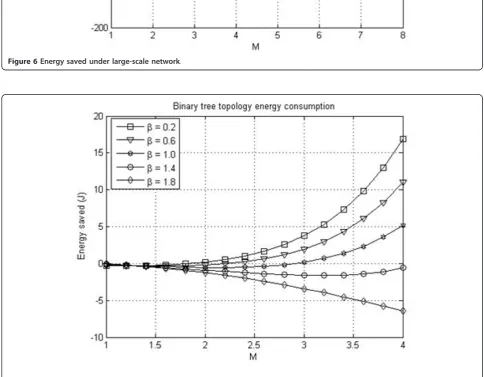
4. Performance evaluation
In this section, we present the simulation results of reverse sector theory, optimization division theory and beacon cluster routing algorithm. First, we set some basic parameters as follows:Ebis 0.36 J, density of sen-sor nodes in mini-sector ris 0.3 per square meters, and the transmission range of each sensor nodes is fixed to 5 m. According to the analysis in Section 3, we can obtain the results of reverse sector theory through simu-lations. As demonstrated in Figure 6, it is clearly shown
that with the growth of M; the curvature of the Egain
curve depends mainly on the vertex angle parameter.
Under the same configured M, decreasingb can simply
enhance the sector type network energy consumption performance by reversing the tree topology.
Based on the simulation results shown above, we
study the relationship between parameterMandb. The
value of M is consisted of the sector radius (R) and the sensor node transmission range (r). In general, sensor node transmission range is limited. Hence, we can regard Mas mainly depends on R. It decides the cover-age region of the local sensor network. If the value of the sector radius is small, with the growing ofb, reverse topology may not achieve energy saving effect as shown in Figure 7. On the other hand, when the network scale is relatively small, large value ofbcannot be acceptable
for the cases such as b= 1.4 and b= 1.8 as shown in
Figure 7. However, with large sector vertex angle,
enlar-ging the coverage of sensor network via increasing R,
reverse topology still outperform the conventional method, which is the only way to optimize the network in this scenario. Note that choosing a proper value ofb can achieve more energy gain with same network scale.
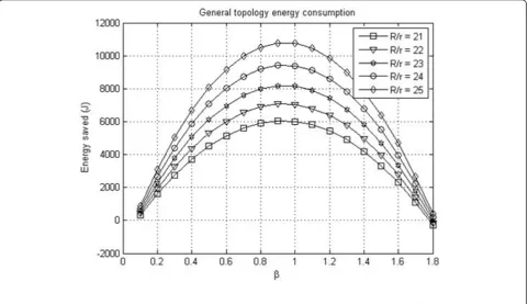
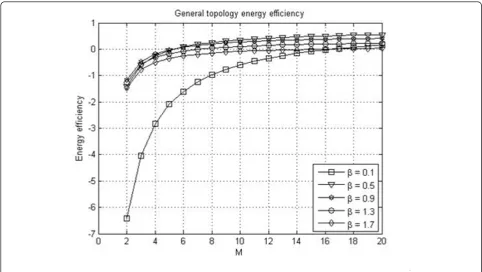
In Figures 8 and 9, with the growth of network scale, energy efficiency ranks with the vertex angle of divided
Figure 5Beacon cluster routing with multiple mobile gateway.
Table 2 Routing table according to the combination of beacon cluster id
Priority Optional beacon cluster id notification
Traffic flow direction decision
2 {Cluster #2} NN #1
Figure 6Energy saved under large-scale network.
sector, but while the parameter⌈R/r⌉maintains in small
section such as lower than 20, small b as 0.1 cannot
achieve high energy efficiency.
According to the simulation results shown above, we can further analyse meaningful guidelines in practical implementation of sensor networks. As illustrated in Fig-ure 8, we observe that even in suboptimal vertex angle such as 1.7, the reverse process can still make the
network more energy efficient than non-reverse one as the energy saving gain keeps increasing with respect to the ratio of coverage radius and transmission radius growth.
As depicted in Figures 10 and 11, after expanding the range of variable ⌈R/r⌉, energy efficiency curves trends to be smooth and gradually approach the theory limita-tion ofEefficient. Thus, we can conclude that if the scale of a sector is configured properly, the reverse sector can save more energy than normal sector in terms of redu-cing hop count in the WSN. Through simple splitting and reverse process, energy efficiency can be enhanced by selecting proper divided vertex angle of each sector on the basis of network coverage and transmission cap-ability of sensor nodes.
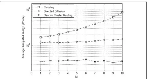
After the WSN has been properly divided into sectors, beacon cluster routing algorithm can enhance the energy conservation performance of each sensor nodes. As illustrated in Figure 12, we compare beacon cluster routing with two conventional routing algorithms for average dissipated energy in network. The network topology and division in the simulation is set as shown in Figure 4, sensor nodes in the network are divided into six different beacon clusters in beacon cluster rout-ing scenario. However, for floodrout-ing and directed diffu-sion routing mechanisms, sector dividiffu-sion is unnecessary, and multiple sinks collect sensor data at the same time.
Figure 8Energy saved under general topology.
Figure 10Energy efficiency under small-scale network.
Note that flooding is set as the benchmark for the per-formance comparison, and even diffusion performs much better than flooding. Beacon cluster routing out-performs the diffusion by more than 50% in terms of energy dissipation. Noticeably, beacon cluster routing dissipates less energy than these two conventional mechanisms since additional routing data exchanging procedures are replaced by local computation.
Figure 13 shows the delay performance comparison of three routing algorithms. As mentioned above, beacon cluster routing algorithm transfers the routing consump-tion into local computaconsump-tion consumpconsump-tion, each sensor nodes can deliver the packets immediately when the beacon broadcasting arrives. Thus, these three routing algorithms are separated with different order of magni-tude in the delay performance comparison. With the increase of network scale, beacon cluster routing algo-rithm shows lower growth rate of network delay while the flooding obviously deteriorates network transmission efficiency. Furthermore, it is clearly shown that the bea-con cluster routing is more efficient than the diffusion approach.
5. Conclusions
In this article, we proposed a beacon cluster based rout-ing algorithm for the convergence of WSN and cellular network service applications. By virtue of the proposed solutions, it is possible to improve the energy and
information collection efficiency in WSN. With the opti-mal network pre-implementation according to the sector splitting scheme, sub-optimization can be achieved in each divided beacon clusters. Accordingly, the perfor-mance of the whole network is optimized via optimal division during the routing procedure. More than 50% of the energy consumption can be saved comparing with conventional network. Furthermore, it is possible to reduce the re-clustering communication overhead since the change of routes between the sensor nodes is minimized. Sensor network topology can adapt to the data collection pattern of real-time quantity and position of mobile gateways flexibly. Meanwhile the re-routing expenditure has been transformed to lower the distribu-ted calculation consumption in the sensor network.
Analysis in this article is considered in the worst situa-tions such as full binary tree while in practical scenarios, network structure can be simpler. This indicates that we have given the lower bound of the performance evalua-tion. With the optimization scheme we proposed in practical implementation, network performance can out-perform our estimation in this paper. Trade-off between network scale and divided angle is helpful for network implementation. While we enlarge the scale of local sen-sor network via installing new sensen-sor nodes for new requirement, divided angle of certain sectors should be re-configured in order to maintain the network work in optimal energy efficient status. Similarly, we may
reconfigure the density of the sensor nodes which in turn will decrease the transmission rage of single node to reach the goal of energy saving. Finally, we have pre-sented simulation results to show the performance of the proposed algorithm. In addition, our proposed algo-rithms can be considered to further optimize in large scale wireless networks [20].
Author details
1Shanghai Institute of Micro-system and Information Technology (SIMIT),
Chinese Academy of Sciences (CAS), Shanghai, China2The State Key Laboratory of Integrated Services Networks (ISN), China3Renesas Tele. Tech.
(Beijing) Ltd., Shanghai, China4Shanghai Advanced Research Institute,
Chinese Academic of Science, Shanghai, China
Competing interests
Partial content is patented by Renesas Tele. Tech. (Beijing) Ltd., Shanghai, China.
This work is supported by the National Science and Technology Major Project of the Ministry of Science and Technology of China under Grant No. 2009ZX03005-002-01, and National High-tech R&D Program (863 Program) of China under Grant No. 2009AA012002.
This work is partially supported by the open research fund of the State Key Laboratory of Integrated Services Networks, Xidian University, China, and Natural Science Foundation of Shanghai under Grant 10ZR1436000, National High-Tech R&D Program (863 Program) of China under Grant
No.2011AA01A105.
Received: 15 July 2011 Accepted: 6 March 2012 Published: 6 March 2012
References
1. D Estrin, R Govindan, J Heidemann, S Kumar, Next century challenges: scalable coordination in sensor networks, in5th Annual International Conference on Mobile Computing and Networking (MobiCom 1999), Seattle, WA, 1999, pp. 263–270
2. J Heidemann, F Silva, C Intanagonwiwat, R Govindan, D Estrin, D Ganesan, Building efficient wireless sensor networks with low-level naming. in Symposium on Operating Systems Principles. New York, 200135(5), 146–159 3. G Pottie, W Kaiser, Wireless integrated network sensors. Commun ACM.
43(5), 51–58 (2000). doi:10.1145/332833.332838
4. S Hedetniemi, A Liestman, A survey of gossiping and brocadcasting in communication networks. IEEE Network.18(4), 319–349 (1988) 5. J Gao, L Guibas, J Hershberger, L Zhang, A Zhu, Geometric spanners for
routing in mobile networks, in2nd ACM International Symposium on Mobile Ad Hoc Networking and Computing (MobiHoc 2001), New York, 2001, pp. 45–55
6. L Zhao, G Liu, J Chen, ZW Zhang, Flooding and directed diffusion routing algorithm in wireless sensor networks, inNinth International Conference on Hybrid Intelligent Systems, Shenyang, 2009, pp. 235–239
7. WR Heinzelman, J Kulik, H Balakrishnan, Adaptive protocols for information dissemination in wireless sensor networks, inProceedings of the ACM MobiCom’99, Seattle, WA, 1999, pp. 174–185
8. C Intanagonwiwat, R Govindan, D Estrin, Directd diffusion: a scalable and robust communication paradigm for sensor networks, MobiCom‘00 Proceedings of the 6th annual international conference on Mobile computing and networking, New York, 2000, pp. 56–67
9. K Hwang, D Eom, Adaptive sink mobility management scheme for wireless sensor networks. Lecture Notes in Computer Science (LNCS).4159(2006) 10. G Wang, T Wang, W Jia, M Guo, HH Chen, M Guizani, Local update-based routing protocol in wireless sensor networks with mobile sinks, ICC‘07. IEEE International Conference, Glasgow 3094–3099 (2007)
11. J Li, L Huang, G Wang, A novel clustering algorithm by using mobile gateways in densely deployed sensor networks. inICIA 2008. International Conference on Information and Automation1553–1559 (2008)
12. K Langendoen,Medium Access Control in Wireless Networks, chapt. Energy-Efficient Medium Access Control, (Nova Science Publishers, 2008), pp. 535–560
13. M Dohler, D Barthel, F Maraninchi, L Mounier, S Aubert, C Dugas, A Buhrig, F Paugnat, M Renaudin, A Duda, M Heusse, F Valois, The ARESA project: facilitating research, development and commercialization of WSNs, in4th Annual IEEE Communications Society Conference on Sensor, Mesh and Ad Hoc Communications and Networks (SECON), San Diego, CA, USA, pp. 590–599 (June 2007)
14. C Dugas, Configuring and managing a large-scale monitoring network solving real world challenges for ultra-low powered and longrange wireless mesh networks. Int J Netw Manag.15, 269–282 (2005). doi:10.1002/nem.573 15. A Bachir, M Dohler, T Watteyne, K Leung, Mac essentials for wireless sensor
networks. IEEE Commun Surv Tutor.12(2), 222–248 (2010)
16. P Gupta, PR Kumar, The capacity of wireless networks. IEEE Trans Inf Theory. 46(2), 388–404 (2000). doi:10.1109/18.825799
17. A El-Hoiydi, Aloha with preamble sampling for sporadic traffic in ad hoc wireless sensor networks, inICC, vol. 5. New York, NY, IEEE, 2002, pp. 3418–3423
18. J Hill, D Culler, Mica: a wireless platform for deeply embedded networks. IEEE Micro.22(6), 12–24 (2002). doi:10.1109/MM.2002.1134340 19. W Ye, F Silva, J Heidemann, Ultra-low duty cycle MAC with scheduled
channel polling, in4th ACM Conference on Embedded Networked Sensor Systems (SenSys), Boulder, CO, ACM, pp. 321–334 (November 1–3 2006) 20. X Wang, W Huang, S Wang, J Zhang, C Hu, Delay and capacity tradeoff
analysis for motioncast. IEEE/ACM Trans Netw.19(5), 1354–1367 (2011)
doi:10.1186/1687-1499-2012-86
Cite this article as:Xiaet al.:Beacon routing algorithm in wireless sensor networks with mobile gateway.EURASIP Journal on Wireless
Communications and Networking20122012:86.
Submit your manuscript to a
journal and benefi t from:
7 Convenient online submission
7 Rigorous peer review
7 Immediate publication on acceptance
7 Open access: articles freely available online
7 High visibility within the fi eld
7 Retaining the copyright to your article