Volume 2009, Article ID 609386,7pages doi:10.1155/2009/609386
Research Article
Separate Turbo Code and Single Turbo Code Adaptive
OFDM Transmissions
Lei Ye
1and Alister Burr
21Department of Communication Engineering, University of Chongqing, Chongqing 400044, China 2Department of Electronics, University of York, Heslington, York YO10 5DD, UK
Correspondence should be addressed to Lei Ye,[email protected]
Received 30 June 2008; Revised 22 December 2008; Accepted 18 January 2009
Recommended by Yan Zhang
This paper discusses the application of adaptive modulation and adaptive rate turbo coding to orthogonal frequency-division multiplexing (OFDM), to increase throughput on the time and frequency selective channel. The adaptive turbo code scheme is based on a subband adaptive method, and compares two adaptive systems: a conventional approach where a separate turbo code is used for each subband, and a single turbo code adaptive system which uses a single turbo code over all subbands. Five modulation
schemes (BPSK, QPSK, 8AMPM, 16QAM, and 64QAM) are employed and turbo code rates considered are 1/2 and 1/3. The
performances of both systems with high (10−2) and low (10−4) BER targets are compared. Simulation results for throughput and
BER show that the single turbo code adaptive system provides a significant improvement.
Copyright © 2009 L. Ye and A. Burr. This is an open access article distributed under the Creative Commons Attribution License, which permits unrestricted use, distribution, and reproduction in any medium, provided the original work is properly cited.
1. Introduction
When transmitted in time dispersive channels, the bit error rate (BER) achieved on different orthogonal frequency-division multiplexing (OFDM) subcarriers depends on the frequency domain channel transfer function. The bit errors are normally concentrated in a few severely faded subcarriers in conventional nonadaptive OFDM systems. In the rest of the subcarriers, there are normally no bit errors. If we can identify these high BER subcarriers and apply more powerful, lower rate forward error correction (FEC) codes, the overall BER of the whole OFDM frame will be improved, while employing higher order modulation and higher rate codes on the high-quality subcarriers can improve overall throughput.
Adaptive modulation was proposed for exploiting the time variant Shannonian channel capacity of fading channel by Steele and Webb [1]. In addition to excluding some fading subcarriers and varying the modulation mode, that is adaptive modulation, code rate can also be adapted. Subse-quently, Tang [2] contributed an intelligent learning scheme for the appropriate adjustment of switching thresholds. Bizzarri et al. proposed adaptive space-time-frequency cod-ing schemes for multiple-input multiple-output (MIMO)
OFDM in [3]. In the present paper, we propose the use of adaptive modulation modes and adaptive code rates for turbo-coded OFDM in two different ways: a single turbo code scheme, and a separate turbo code scheme. In both schemes, each subband [4] contains a set of subcarriers for which the modulation mode and turbo code rate is determined by the signal-to-noise ratio (SNR) of subcarriers in this subband, but in the single turbo code scheme only one turbo code is used over all subbands, while the separate turbo code scheme uses a distinct turbo code frame for each subband.
In the remainder of this paper, we first give a description of the system structure of both adaptive turbo-coded OFDM schemes. We then discuss and compare the numerical results of simulation. The final section gives a summary of the work.
2. System Structure
Data S/P
P/S
Turbo coding and modulation
Turbo coding and modulation
Scheme type decision
Turbo decoding and demodulation
Turbo decoding and demodulation
Turbo decoding and demodulation
Interleave to OFDM frame
Interleave to turbo
code frame
IFFT
FFT Channel
Add CP
Rem CP
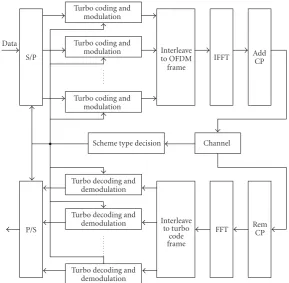
Figure1: System structure of separate turbo code adaptive system.
Then, separate turbo coding and modulation are employed for each subband. At the transmitter, before adding a cyclic prefix, an inverse fast Fourier transform (IFFT) is applied to the OFDM frames.
After transmission through the fading channel, an FFT is applied to the received signal after removal of the cyclic prefix. Then, each subband is demodulated and decoded separately. The structure of the separate turbo coded adaptive OFDM system used is illustrated inFigure 1.
For the single turbo code adaptive OFDM scheme, the information bits are firstly turbo coded by a single turbo code, then modulated separately for each subband. In the same way, at the receiver, the signal from the output of the FFT is demodulated separately then decoded as a single turbo code frame. In this scheme, when other parameters are the same, the length of turbo code used is much longer than for the separate turbo code scheme, therefore it can get better system performance with the single turbo code adaptive OFDM system. The structure of the single turbo code adaptive OFDM system used is illustrated inFigure 2.
2.1. Transmission Block Structure. In the separate turbo code scheme, the OFDM frame is divided into several subbands, and the turbo code frame combines the same subband of several OFDM symbols.Figure 3shows the structure of the block and the relationship of turbo code frame and OFDM frame of the separate turbo code scheme.
In the single turbo code scheme, the OFDM frame is also divided into several subbands, each subband using a different modulation scheme. The turbo code frame combines several OFDM symbols. Figure 4shows the structure of the block
and the relationship of turbo code frame, OFDM frame, and cyclic prefix of single turbo code scheme.
Figure 3shows that the number of modulated symbols
in each turbo code frame after coding and modulation should be the same (because the number of subcarriers in each subband is the same). Hence, if different modulation mode and code rate are used for different turbo code frames (different subbands), the length of turbo code must be different for each frame, and therefore the length of the turbo code interleaver must be variable. As shown inFigure 4, the turbo code length of the single turbo code system is also variable because the modulation scheme for the subbands changes. In this work, we choose to use an S-random interleaver for both schemes, which was first described in [5], and hence we need to provide a variable-length S-random interleaver.
Popovski presents a flexible length S-random interleaver algorithm in [6]. In our simulation, we provided a simplified algorithm to generate a flexible S-random interleaver with the same S-parameter as a given interleaver.
Assume that we already have a length K S-random interleaver with S-parameterS, denoted byπK and letL > K
be the maximal interleaver length of interest. Starting from N =K, each permutationπN+1of lengthK < N+ 1≤Lis
obtained from the permutationπNby insertingNat position
jNas follows:
πN+1(i)= ⎧ ⎪ ⎪ ⎨ ⎪ ⎪ ⎩
πN(i), 0≤i < jN,
N, i=jN,
πN(i−1), jN < i≤N.
Data
Figure2: System structure of one turbo code adaptive system.
Subband 1
Figure 3: Transmission block structure of separate turbo code adaptive system.
The lengthN+ 1 S-random interleaver is selected using the following steps for given interleaver length N with S-parameter S. For each jN from 0 → N, create an N +
1 permutation using (1) above. For each, calculate D = |πN+1(p)−πN+1(jN)|, for
Figure4: Transmission block structure of one turbo code adaptive system.
Then, ifDis larger thanSfor allp, this permutationπN+1
is a lengthN+ 1 S-random interleaver with S-parameterS. Otherwise, we calculateDfor the next permutationπN+1.
Using this algorithm, all the length L > K S-random interleaver may easily be obtained. Once we find all the positions jfor all the lengths of interest, the interleaver can be defined using very simple rules by adding positions to the original interleaver. The system needs only to store the origi-nal length interleaverπKand the valuesjK,jK+1,. . .,jL−1.
10−8 64QAMσlength=4602 64QAMσ=2 length=27642 Figure5: BER of nonadaptive turbo coded OFDM system.
SNR of each subcarrier needs to be calculated. We assume that the impulse response of the fading channel is time-invariant for the duration of one OFDM symbol. Therefore, the frequency domain channel transfer functionHn can be
determined by a Fourier transform of the impulse response. The received data symbolsRncan be expressed as
Rn=Sn·Hn+nn, (3)
where Sn is transmission signal andnn is Gaussian noise.
Since the channel’s frequency domain transfer functionHnis
independent of the noise power in each subcarrier, the local SNR of each subcarrierncan be expressed as
γn=Hn2·γ, (4)
where γ is the overall SNR. If there is no inter-subcarrier interference (ISI), or interference from other sources, the valueγndetermines the bit error probability of subcarriern.
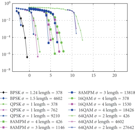
Then, the threshold for the given long-term BER target should be determined. Five modulation schemes, namely, BPSK, QPSK, 8AMPM, 16QAM, and 64QAM are used in these adaptive turbo coded OFDM systems. The turbo code rate is 1/2. Therefore, there are in total 5 modulation and code schemes for modulation and coding, plus the nontransmission case. By simulating the nonadaptive OFDM system with these schemes separately, the SNR thresholds for a given long-term target BER can be determined. The length of turbo code affects the BER performance of the turbo code especially when the turbo code length is short. This will affect the adaptive system threshold as well.Figure 5gives the BER curves for each of these schemes with different length of turbo code. Here, we used soft-output demodulation in this system. From this figure, the threshold for the BER target can be determined.
For subband adaptive OFDM transmission, there are several subcarriers with different local SNRs in each subband;
0
Figure6: Rayleigh fading channel impulse response.
therefore the lowest quality subcarrier in the subband is chosen to compare with the threshold, which is fixed threshold adaptation.
In the fixed threshold adaptation, using a conservative approach, the worst subcarrier in each subband is used for channel quality estimation, to determine the modulation mode and the code rate. Therefore, the overall BER in one subband is normally lower than the BER target. If the overall BER can be closer to the BER target (though still below it) by choosing a more suitable modulation mode or code rate, the throughput of the system will be higher. Therefore, we propose an optimal adaptation algorithm giving a better tradeoffbetween throughput and overall BER by choosing more suitable schemes for each subband on the basis of fixed threshold adaptation.
Firstly, the local SNR for each subcarrier is calculated. Then, the fixed threshold adaptation algorithm should be used to calculate the original schemeAnfor each subband.
For each subband, if a higher order schemeAn+1is employed,
the estimated BER of each subcarrier in the subband can be obtained from the BER curve of the nonadaptive system
(Figure 5), and hence the estimated average BER of this
subband with this scheme An+1 can be obtained. If the
estimated average BER is still lower than the BER target, then we calculate the estimated average BER of this subband with higher order schemesAn+2 andAn+3, and so forth, till
the estimated average BER is worse than the BER target. By using this algorithm, the highest order scheme, and therefore the highest throughput, which can fulfil the BER target is found.
3. Numerical Results
10−8 10−6 10−4 10−2 100
BER
−5 0 5 10 15 20 25 30
SNR BPSK
QPSK 8AMPM 16QAM
64QAM
Separate turbo code adaptive system Single turbo code adaptive system
Figure7: BER of separate turbo code system and single turbo code system.
symbols. For schemes of higher order than QPSK, bit-interleaved coded modulation is used [7].
A frequency selective fading channel is assumed in this simulation. The impulse response h(τ,t) was generated using a tapped delay line channel model in which each tap amplitude follows an independent Rayleigh distribution. The impulse response is shown inFigure 6.
In this simulation, perfect knowledge of the channel transfer function at the receiver is assumed. Also the channel impulse response is not changed during one turbo code frame (12 OFDM symbol) block.
3.2. Simulation Results. In our separate turbo code and single turbo code adaptive turbo-coded OFDM system, as mentioned above, there are five modulation modes with code rate 1/2, plus the nontransmission case. In the separate turbo code system, if one subband is determined to employing BPSK, the length of the turbo code frame used in this subband is 282; while for the subbands employing QPSK, 8AMPM, 16QAM, and 64QAM, the length of the turbo code frames are 570, 858, 1146, and 1722, respectively. Compared to the separate turbo code system, the length of the turbo code in the single turbo code adaptive system is much longer. When none of the subbands are marked as nontransmission, the length of a turbo code with BPSK in all subbands is 4602, and the length of a turbo code with 64QAM in all subbands is 27642.
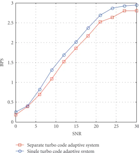
Figure 7illustrates the BER performance of both adaptive turbo coded OFDM systems using these 5 modulation schemes, with the optimal adaptation algorithm. Also
0 0.5 1 1.5 2 2.5 3
BPS
0 5 10 15 20 25 30
SNR Separate turbo code adaptive system Single turbo code adaptive system
Figure8: Throughput of separate turbo code system and one turbo code system.
Figure 8shows the throughput in bits per second (bps) of
both systems using same adaptation algorithm.
The dotted lines inFigure 7are the BER performances of the nonadaptive OFDM system with 1/2 rate turbo code and the 5 modulation schemes mentioned above. The red solid line with circle in both Figures7 and8 are the BER and throughput performance for the separate turbo code system, while the blue solid line with square in both figures is the BER and throughput performance for the single turbo code system. These figures show that the single turbo code adaptive OFDM system can provide better bps throughput performance than the separate turbo code adaptive OFDM system with same adaptation algorithm. Both of the systems fulfil the BER target, but the single turbo code system is closer to it.
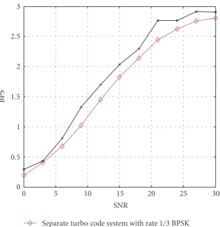
3.3. Simulation Results with Rate 1/3 BPSK. As shown in Figure 8, the difference of throughput for these two schemes is smaller when the overall SNR is low. The reason for this is when the SNR is low, there are more subbands with no transmission. So, the length of turbo code in one turbo code system is similar to the length in the separate turbo code system. Hence, a more powerful, lower rate FEC code can be included in the adaptation algorithm to reduce the number of nontransmission subbands. In this case, we choose code rate 1/3 with BPSK as another option.
X
X P1
P1 x x x x
x
x x x
P2
P2
X0 P10P20 X1 P11P21 X2 P12 P22
X0 P10 X1 P21 X2 P12 X3 P23 X4
1 1 1 1 1 1 1 1
1 1 1 1 1 1 1 1
1
1
1
1 1
1
1 1 1
1
1 1 1 1 1 1 1
1 1 1 1 1 1 1
Rate 1/2
Figure9: Puncture process of different code rate turbo code (“1” in the table means the code bit is included, “x” means the code bit is punctured).
10−8 10−6 10−4 10−2 100
BER
−5 0 5 10 15 20 25 30
SNR BPSK
QPSK 8AMPM 16QAM
64QAM
Separate turbo code system with rate 1/3 BPSK Single turbo code system with rate 1/3 BPSK
Figure10: BER of separate turbo code system and one turbo code system with rate 1/3 BPSK.
Figure 10illustrates the BER performance of both adap-tive turbo coded OFDM systems using these 6 modulation and code schemes, with the optimal adaptation algorithm.
AlsoFigure 11shows the throughput in bps of both systems
using same adaptation algorithm.
The magenta solid lines with cross in both Figures10and 11 are the BER and throughput performance for separate turbo code system with code rate 1/3 BPSK, while the black solid lines with star in both figures are the BER and throughput performance for the single turbo code system. The BER performance of both systems is similar to the system without rate 1/3 BPSK, but the throughput performance at
0 0.5 1 1.5 2 2.5 3
BPS
0 5 10 15 20 25 30
SNR
Separate turbo code system with rate 1/3 BPSK Single turbo code system with rate 1/3 BPSK
Figure 11: Throughput of separate turbo code system and one turbo code system with rate 1/3 BPSK.
lower SNR is slightly higher than the systems without rate 1/3 BPSK.
3.4. Simulation Results for Lower BER Target 10−4. The advantage of the single turbo coded schemes in the cases simulated here is relatively small because of the relatively high BER target, at which point the required SNR is not much affected by the code length. So, a lower BER target of 10−4was chosen for detailed simulation.
Figure 12illustrates the BER performance of both adap-tive turbo-coded OFDM systems with this new BER target.
AlsoFigure 13shows the throughput in bps of both systems
10−8 10−6 10−4 10−2 100
BER
−5 0 5 10 15 20 25 30
SNR BPSK
QPSK 8AMPM 16QAM
64QAM
Separate turbo adaptive system Single turbo code adaptive system
Figure12: BER of separate turbo code system and one turbo code
system with BER target 10−4.
0 0.5 1 1.5 2 2.5 3
BPS
0 5 10 15 20 25 30
SNR Separate turbo code low ber target Single turbo code system with low ber target
Figure 13: Throughput of separate turbo code system and one
turbo code system with BER target 10−4.
performance for the single turbo code system. For this BER target, the single turbo code adaptive turbo coded OFDM system is still out performance of the separate turbo code adaptive system.
4. Summary
This paper has presented two adaptive modulations and code rate turbo coded OFDM schemes, namely the separate turbo code system and the single turbo code system, including descriptions of the system structures and transmission signal block structure design. A flexible length S-random interleaver algorithm is used. Also the performances of two adaptive systems have been compared. As shown in the numerical results, for both high and low BER targets, the sin-gle turbo code adaptive system provides better performance by using longer turbo codes.
The gap between the turbo-coded systems and the Shannon bound remains large, indicating that substantial further gains should be possible, given that turbo codes are in principle able to approach very closely to this bound. The reasons for the gap here include the rather simple approach to coded modulation for higher order modulation, and that for low code rates the turbo frame (in terms of data bits) is relatively short in both systems. Future work will investigate the use of improved coded modulation and the effect of more realistic channel estimation.
References
[1] R. Steele and W. T. Webb, “Variable rate QAM for data
transmission over Rayleigh fading channels,” inProceedings of
IEEE Wireless Conference, pp. 1–14, Calgary, Canada, July 1991. [2] C. Tang, “An adaptive learning approach to adaptive
mod-ulation,” in Proceedings of International Conference on Third
Generation Wireless and Beyond (3Gwireless ’01), San Francisco, Calif, USA, May-June 2001.
[3] E. Bizzarri, A. S. Gallo, and G. M. Vitetta, “Adaptive
space-time-frequency coding schemes for MIMO OFDM,” inProceedings of
IEEE Global Telecommunications Conference (GLOBECOM ’04), vol. 2, pp. 933–937, Dallas, Tex, USA, November-December 2004.
[4] L. Hanzo, C. H. Wong, and M. S. Yee, Adaptive Wireless
Transceivers: Turbo-Coded, Turbo-Equalized and Space-Time Coded TDMA, CDMA, and OFDM Systems, Wiley-IEEE Press, Madison, Wis, USA, 2002.
[5] S. Dolinar and D. Divsalar, “Weight distributions for turbo codes using random and nonrandom permutations,” Tech. Rep. TDA PR 42–122, Jet Propulsion Laboratory, Pasadena, Calif, USA, August 1995.
[6] P. Popovski, L. Kocarev, and A. Risteski, “Design of
flexible-length S-random interleaver for turbo codes,”IEEE
Communi-cations Letters, vol. 8, no. 7, pp. 461–463, 2004.
[7] G. White, Optimised turbo codes for wireless channels, Ph.D.