R E S E A R C H
Open Access
Spectral efficiency of multi-user
millimeter wave systems under single path
with uniform rectangular arrays
Weiqiang Tan
1,2, Shi Jin
2*, Chao-Kai Wen
3and Tao Jiang
4Abstract
In this paper, we investigate the downlink achievable ergodic spectral efficiency (SE) of a single-cell multi-user millimeter wave system, in which a uniform rectangular array is used at the base station (BS) to serve multiple single-antenna users. We adopt a three-dimensional channel model by considering both the azimuth and elevation dimensions under single-path propagation. We derive the achievable ergodic SE for this system in with maximum ratio transmission precoding. This analytical expression enables the accurate and quantitative evaluation of the effect of the number of BS antennas, signal-to-noise ratio (SNR), and the crosstalk (squared inner product between different steering vectors) which is a function of the angles of departure (AoD) of users and the inter-antenna spacing. Results show that the achievable ergodic SE logarithmically increases with the number of BS antennas and converges to a value in the high SNR regime. To improve the achievable ergodic SE, we also propose a user scheduling scheme based on feedback of users’ AoD information and obtain the maximum achievable ergodic SE. Furthermore, we consider a dense user scenario where every user’s AoD becomes nearly identical and then derive the system’s minimum achievable SE.
Keywords: Millimeter wave communications, Multi-user MIMO, Maximum ratio transmission, Spectral efficiency, User scheduling, Uniform rectangular array
1 Introduction
With the proliferation of smart wireless services such as high-definition video streaming, cell broadcasting, and mobile TV, mobile data traffic is envisioned to grow 1000-fold by 2020 [1]. To meet the predicted traffic demand, millimeter wave (mmWave) communications, which oper-ates in the 30–300 GHz band, appear to be a promis-ing candidate for next generation cellular systems that support multiple gigabit-per-second data rates [2]. Some recent results have demonstrated that the use of mmWave communications helps to achieve gigabytes per second (Gbps) data rates in both indoor [3] and outdoor wireless networks [4].
One salient feature of mmWave communications is the significant decrease of carrier wavelength, which allows
*Correspondence: [email protected]
2National Communications Research Laboratory, Southeast University, Nanjing 210096, People’s Republic of China
Full list of author information is available at the end of the article
a large number of antennas to be packed into a base station (BS) or an access point. The excessive use of trans-mit antennas, known as massive input multiple-output (MIMO) technology [5, 6], provides substantial array gains to combat severe path loss and establishes reli-able communication links. Furthermore, deployment of large antenna arrays at the BS enables efficient precoding for multiple data streams, thus improves the spectral effi-ciency and energy effieffi-ciency [7, 8]. To take advantage of the available space at the BS of a massive MIMO system, it is desirable to arrange the antenna elements as a uniform linear array (ULA), a cubic array, or a uniform rectangular array (URA)[9].
Most importantly, rectangular or cubic arrays enable not only horizontal beam pattern adaptation but also vertical beam pattern adaptation, that is, they enable three-dimensional (3D) beamforming, which provides an additional degree-of-freedom for interference suppres-sion [10]. Therefore, exploitation of 2D antenna array
configurations such as uniform circular array (UCA) or URA in mmWave MIMO systems is desirable.
1.1 Related works
Several aspects of mmWave MIMO communications, including channel measurements [11–13], channel esti-mation [14–16], hybrid analog/digital precoding design [17–20], multiple amplify-and-forward (AF) relaying networks [21–23], and multiple-cell cooperative communi-cation [24], have been investigated in prior works. In par-ticular, various potential techniques for mmWave cellular systems were specified in [11] by considering mmWave channel characteristics. The measurements in [12, 13] demonstrated that mmWave channels have limited light-of-sight (LoS) components and are related to the steering vectors which depend on the antenna array topologies of the transmitter and receiver. To enhance the beamforming gains and enable multiplexing of multiple data streams, hybrid precoding techniques were proposed in [19], where the processing was divided between the analog and dig-ital domains. In [17], a hybrid precoding technique that requires only partial knowledge of mmWave channels was presented. The work in [19] proposed a low-complexity hybrid analog/digital scheme, which effectively relaxes the hardware constraints for downlink multi-user mmWave systems. A similar investigation was conducted in [14]. In [15], a compressed sensing-based channel estimation was proposed by exploiting the sparse nature of large mmWave MIMO channels. By leveraging the static nature of the angle of arrival and angle of departure (AoD), the work in [16] studied the performance of zero-forcing (ZF) beam-forming with limited feedback. More recently, authors in [18] studied a multi-user MIMO downlink transmis-sion scheme over Rician fading channels, where the BS exploits statistical channel state information (CSI). From these prior works, we notice that fully utilizing static or statistical information is one of the key requirements for massive mmWave MIMO systems.
Despite these existing body of literature, only few ana-lytical results are available on the achievable ergodic spectral efficiency (SE) of multi-user mmWave MIMO systems, particularly for the 3D channel model. Owing to different propagation characteristics at such high frequen-cies, the coverage and rate trends differ drastically from the conventional cellular systems. In [25], the coverage and rate performance were studied for mmWave systems. The results of [25] showed that the achievable rate is sen-sitive to the density of BSs and the blockage distribution. In multi-user mmWave MIMO systems, linear precoding method such as ZF can perform almost as well as dirty paper coding, the multi-user mmWave MIMO system analysis of which is studied in [26]. However, the compu-tation complexity due to the inverse of large dimensional matrix makes it inappropriate for real-time processing. In
contrast, maximum ratio transmission (MRT) precoding is simple and exhibit near optimal performance (though worse than ZF) has received significant research interest [5]. Hence, studying the achievable ergodic SE of multi-user mmWave systems using MRT precoding is of special interest.
1.2 Summary of contributions
In this paper, we investigate the achievable ergodic SE with multiple antennas and URA configuration at the BS. In particular, we develop analytical expressions to gain insight into the performance. Our contributions are summarized as follows:
• We present an exact closed-form expression for the achievable ergodic SE by using MRT precoding under the assumption that the BS has perfect channel state information. We also present the achievable ergodic SE that is valid for massive numbers of antenna elements in the high-SNR regime. We make use of these results to discuss the impact of the number of BS antennas, SNR, crosstalk, users’ AoD, and the inter-antenna spacing.
• To improve the performance of MRT precoding, a user scheduling scheme is proposed by exploiting statistical users’ AoD information. We select a set of user group satisfying the orthogonal criterion and derive the corresponding maximum achievable SE. We also consider a dense user scenario and present an expression for the minimum achievable SE.
The remainder of this paper is organized as follows. Section 2 introduces the system model. Section 3 derives an exact closed-form expression of the achievable ergodic SE for a finite number of users and antenna elements. Based on these analytical results, several practical insights are presented. Numerical and simulation results are also provided in Section 4, and we conclude the paper in Section 5.
Notation—Throughout the paper, matrices and vectors are expressed as upper and lower case boldface letters, respectively. Moveover,(·)H denotes the conjugate
trans-pose; · and |·| represent the Euclidean norm and absolute value, respectively; E{·} and ⊗ represent the expectation operator and kronecker product, respectively;
IMdenotes anM×Midentity matrix;edenotes the base
of the natural logarithm; the notationx∼CN(0, 1)means thatxis the complex Gaussian random variable with mean zero and variance one; e is the Euler-Mascheroni con-stant; Ei(x)= −−x∞ e−ttdt denotes the exponential inte-gral function ([27], Eq. (8.211.1));Eh(x)=
∞
1 t−he−xtdt is the exponential integral of orderh([27], page xxxv), and
2 System model
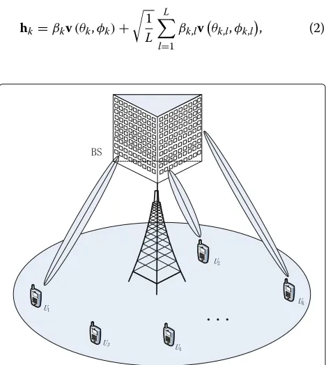
We consider the downlink of a single-cell multi-user mmWave MIMO system where a URA configuration is deployed at the BS as shown in Fig. 1. We assume that the BS is equipped withNt transmit antennas to
simul-taneously serveK single-antenna users (K Nt). The
received signal at thek-th user can be expressed as
yk=√ρgkhkHwksk+√ρgk K
j=1,j=k
hHkwjsj+nk, (1)
whereρandgk(k=1,. . .,K) denote the average SNR and
antenna array gain for userk,wk, andwjis unit-norm
pre-coding vectors of userkand userj, respectively,sk andsj
denote the transmit zero-mean Gaussian symbols for user
k and userj, respectively,nk ∼ CN(0, 1) is the additive noise at thek-th user, andhk ∈ CNt×1 is the mmWave
channel vector from the BS to thek-th user. We assume that the inputs must satisfy a transmit power constraint such thatwj =1 andE{|sj|2} = 1 forj= 1,. . .,Kand
consider the equal power allocation scheme.
2.1 Channel model
A mmWave channel is composed of a single-path propa-gation component considering the dominant path and a set of multi-path components because of the highly direc-tional and quasi-optical nature of electromagnetic wave propagation at the mmWave frequency [12]. Hence, hk
can be accurately modeled as [28–30]
hk=βkv(θk,φk)+
1
L L
l=1
βk,lv
θk,l,φk,l
, (2)
Fig. 1A schematic diagram of the multi-user MIMO mmWave system, where a BS equipped with a URA servesKusers
whereβk andβk,l are the complex gain of LoS path and
multi-path components for thek-th user, respectively, i.e.,
βk (βk,l)∼CN(0, 1),Ldenotes the number of multi-path components,φkandθkare the azimuth and elevation AoD of thek-th user, respectively, andv(θk,φk)is the steering vector with respects to antenna array configuration.
For a mmWave wireless propagation, the effect of multi-path components are marginal and LoS component is the predominant mode since the path loss of multi-path com-ponents is much larger than that of the LoS component. Furthermore, as measurement reports about mmWave channel [28, 31], the magnitude of multi-path components are generally 5 to 10 dB weaker than the LoS predomi-nant component, even there is no multi-path components. Without loss of generality, we neglect the multi-path com-ponents and consider only the single-path component; that is,βk,l =0 forl = 1,. . .,L. Therefore, the mmWave
channel model in (2) can be simplified as
hk=βkvk(θk,φk). (3)
We assume a URA configuration at the BS since it can perform 3D beamforming by employing both the azimuth and elevation dimensions.1 In the far-field regime, the steering vector for the URA configuration is represented by [32]
vk(θk,φk)=vNx⊗vNy, (4)
where
vNx=
1ejk0dxsinθkcosφk· · ·ej(Nx−1)k0dxsinθkcosφk
T
,
vNy=
1ejk0dysinθksinφk· · ·ej(Ny−1)k0dysinθksinφkT
(5) are the steering vectors in the horizontal and vertical directions, respectively. Herein,k0=2π/λis the number of waves andλis the carrier wavelength;Nx andNy are
the numbers of antenna elements placed in the horizontal and vertical dimensions, respectively;dyanddxdenote the
inter-antenna spacing in the horizontal and vertical direc-tions, respectively, which has a linear relationship withλ i.e.,dx = dy= ηλwithηbeing an any positive real
num-ber. Accordingly, the total number of BS antennasNt is
equal toNx×Ny. In the following subsection, we present
the definition of antenna array gain.
2.2 Antenna array gain
Since we consider a URA configuration at the BS, where an antenna gain changes with the transmit antenna pat-tern. According to the 3GPP in [33], the horizontal and vertical antenna radiation pattern adopted can be expressed in dB scale as
GH(φk)=min 12
φk
φ3dB
2 ,Am
and
GV(θk,θtilt)=min 12
θk−θ
tilt
θ3dB
2 ,Am
, (7)
where φ3dB and θ3dB represent the horizontal and ver-tical half-power beamwidth, respectively, Am represents
the maximum attenuation of the array antennas, andθtilt denotes the antenna tilting angle which is allowed to be adjusted within the given interval.
Let us denoteGmax (in dB) as the maximum antenna gain at the antenna boresight. Then, after combining the antenna attenuations and the maximum antenna gain, the resultant antenna gain in dB scale for the k-th user with azimuth angleφk and the elevation angleθk can be formulated as
Gk =Gmax−min{GH(φk)+GV(θk,θtilt),Am}. (8)
To simplify the analysis, we assume Am = ∞. This
assumption is valid when GH(φk)+GV (θk,θtilt) <Am.
With these assumption, we can obtain the antenna gain in linear scale for thek-th user as
gk=10
Gmax
10 −1.2
φ k
φ3dB
2
−1.2
θ k−θtilt
θ3dB
2
. (9) From (9), we observe that the antenna gaingk depends
on the maximum antenna gain, the antenna tilting angle, the azimuth and elevation AoD of thek-th user, and the horizontal and vertical half-power beamwidth, respec-tively. In practice, once the system configuration is com-plete, it means the maximum antenna gain, the antenna tilting angle, and the horizontal and vertical half-power beamwidth is fixed. For the AoD information which includes the azimuth and elevation of the k-th user, changes very slowly and remains constant over a coher-ence time intervals. Compared with the complex gain of LoS path, the AoD information is treated as statistical CSI and assumed to be known. We show the achievable ergodic SE of system in the following subsection.
2.3 Achievable ergodic SE
We assume that the BS has the perfect CSI and employs linear precoding to process the signal before transmitting it to theKusers, the achievable ergodic SE of thek-th user can be written as
Rk =E
log2(1+SINRk)
, (10)
where
SINRk =
ρgkhHkwk2
1+ρgkKk=1,k=jhHkwj
2. (11)
Hence, the total achievable ergodic SE of the system is given by
Rsum=
K
k=1Rk. (12)
To maximize the total achievable ergodic SE in (12) is identical to maximize the achievable ergodic SE of thek -th user in (11) since users are independent of each o-ther. It is worth pointing out that the achievable ergodic SE depends on the choice of the transmit beamforming vec-tor. To maximize the achievable ergodic SE in (11), the optimization aims to find the beamforming vectorswi(i=
1,. . .,K) such that thewkmust simultaneously maximize
the numerator and minimize the denominator of (11). Among different choices, achievable rate achieving non-linear precoders are known to involve high computational complexity. We show the following lemma that presents the optimal beamforming vector maximizingRsumwhen the number of BS antennas grows without bound.
Lemma 1 The achievable ergodic SE in(11) is
maxi-mized when the channel response vectors between different users are orthogonal. With CSI at the BS, the optimal beamforming vector for a URA configuration that maxi-mizes the achievable SE is asymptotically(i.e., Nt → ∞) is given by
woptk = hk
hk
. (13)
Proof In order to maximize (12), we find that the opti-mal beamforming vector wk must simultaneously
max-imize the numerator and minmax-imize the denominator of (11). We first consider the term of the numerator. For LoS channel response vectors, we have
hHkwkλmaxhkwHk
=Ntβk, (14)
where we have used the Rayleigh quotient law. We can see that this maximum of the numerator in (11) is achieved when wk is an eigenvector of hkwHk corresponding to
the maximum eigenvalue, i.e.wk =hk/hk. At the same
time, to maximize the SINR, we must have the following criterion
hHkwj→0. (15)
For a URA configuration, substituting (4) into (15), the inner product term can be calculated as
hHkwj=
1 √
Nt βk
βj Nx
n=1
Ny
m=1
ej(n−1)k0dxδx+j(m−1)k0dyδy,
(16)
where
δx =sinθkcosφk−sinθjcosφj
By applying Eular’s formula ([27], Eq. (1.222.2)), we obtain the following simplified expression
hHkwj=
which converges to zero when the number of BS antennas grows without bound and the AoDs of users are distinct (i.e.φk = φj andθk = θj),2 which leads toδx = 0 and
δy=0. Thus, the above criterion in (15) is satisfied.
From Lemma 1, it is evident that the optimal beamform-ing vectorwoptk is obtained by adopting MRT precoding. This is because when the number of BS antennas grows without bound, the channel steering vectors between dif-ferent users become asymptotically orthogonal to each other. This implies that the interference between differ-ent users is effectively suppressed. Then, the achievable SE attains its maximum value.
By utilizing (3) and (13), the achievable ergodic SE of the
k-th user can be rewritten as
Rk=E
|βk|Nt denotes the normalized factor of the precoding vector while the expectation in (19) is across all channel realizations of the complex gain
βk and steering vector vk. We assume the azimuth and
elevation angles of users are known a priori information because they can be obtained in practice via feedback.3
3 Achievable SE analysis
In this section, we derive a new exact closed-form expres-sion of the achievable ergodic SE for an arbitrary num-ber of BS antennas and investigate its behavior in the high-SNR regime. Based on the analytical expression, we also evaluate the maximum achievable ergodic SE by a user scheduling method and the system’s minimum achievable ergodic SE in a dense user scenario.
3.1 Achievable SE analysis
In this subsection, we focus on deriving closed-form expressions of the achievable ergodic SE by analyzing the SINR in (19). The following theorem is useful to calculate on the achievable ergodic SE when a URA configuration is employed at the BS.
Theorem 1An exact analytical expression for the
achievable ergodic SE with a URA configuration at the BS and MRT precoding is given by
Rk =log2(e)
j=1denote the crosstalk coefficients, i.e.,
aj=
vHkvj2
vj2
, (21)
where the steering vector vk is defined in (4). Note that when the steering vectorvk equals to the itselfvk, we have ak=Nt.
ProofWe first factorize (19) as
Rk =
Therefore,X1,X2,. . .,XKare i.i.d. exponential distributed
random variables with mean 1/Ntand variance 1/Nt2. In
addition, with the help of the results in ([34], Page 552), the pdfs of X = Kj=1Xj andY = Kj=1,j=kXj can be
respectively. By utilizing the pdfs in (26) and (27), we can evaluateI1andI2according to
I1=
By substituting (26) and (27) into (28) and (29), respec-tively, and applying the integral identity ([35], Eq. (13))
& ∞ We can obtain
I1=log2(e)
Subsequently, by substituting (31) and (32) into (22), fol-lowed by some basic algebraic manipulations, we arrive at the desired result.
In Theorem 1, we observe that the closed-form expres-sion for the achievable ergodic SE is a function of the aver-age SNR the number of users and crosstalk coefficients, which depends on the number of BS antennas, inter-antenna spacing and the azimuth and elevation AoDs. This makes it very different to understand the impact when the number of BS antennas is increased. To gain further insights, we have the following result.
Theorem 2In the high-SNR regime (i.e., asρ→ ∞), the achievable ergodic SE can be written as
lim
Proof When SNR increases without bound, (19) can be rewritten as
Then, we can factorize it into as
lim
where the pdfs of the random variableXandYare given in (26) and (27), respectively. We now evaluateI3andI4 according to
By substituting the pdfs of the random variableXand
and
I4=log2(e)
K
j=1,j=k
aKj −3lnaj−e
k=jaj−ak
. (40)
Finally, substituting (39) and (40) into (35) concludes the proof.
Based on Theorem 2, we observe that in high-SNR regime, the achievable ergodic SE is a function of the num-ber of BS antennas, the numnum-ber of users and the crosstalk, which converges to a constant. The reason is both the sig-nal power and the interference power increase as the SNR. This implies that the performance of the system with MRT precoding can severely deteriorate in a high SNR regime. More importantly, from Theorems 1 and 2, we observe the involvement of the crosstalk coefficients. According to the definition ofajin (21), we see that the crosstalk coefficient
mainly depends on the particular antenna array configura-tion at the BS. Once the BS deployment is completed, the crosstalk coefficientajcan be easily acquired. In addition,
other antenna array configuration such as UCA or ULA can be easily applied to Theorems 1 and 2 by plugging the corresponding crosstalk coefficients. The corresponding crosstalk coefficientsaj for these antenna arrangements
can be found in [32, 36].4
In order to proceed, substituting (4) into (21), the crosstalk coefficients aj for URA configuration can be expressed as
aj=
1
Nt
sinNxk0dx
2 δx
sink0dx
2 δx
sin Nyk
0dy
2 δy
sink0dy
2 δy
2
, (41)
whereδxandδyare defined in (17). The crosstalk coeffi-cientsajcan be further simplified as
aj= 1 Nt
(1−cos(Nxk0dxδx))
(1−cos(k0dxδx))
1−cosNyk0dyδy
1−cosk0dyδy
. (42)
According to (42), we see that the effect of the crosstalk coefficient on the achievable ergodic SE is difficult to derive for the general case. Alternatively, we first observe that the normalized crosstalk coefficient depends on the number of BS antennas in the horizontal and vertical planes, inter-antenna spacing in the corresponding hori-zontal and vertical planes, and users’ AoD. In the follow-ing, we present the effect of users’ AoD and inter-antenna spacing on the normalized crosstalk coefficient.
Figure 2 shows the normalized crosstalk versus the azimuth angle of thej-th user and different number of BS antennas. In the simulations, the users’ elevation angles are fixed to beφk =φj= π/4, the azimuth angle of the
30 35 40 45 50 55 60
0 0.1 0.2 0.3 0.4 0.5 0.6 0.7 0.8 0.9 1
Azimuth angle [ ° ]
Normalized Crosstalk a
j
Theoretical Simulations
N
t=1000,400,100,64,36
Fig. 2The normalized crosstalk coefficient versus the azimuth angle of thej-th user for differentNt
k-th user is fixed to beθk =π/6, the inter-antenna spac-ing in horizontal direction is set todx = dy= λ/2, and
the number of BS antennas is 36, 64, 100, 400, and 1000, respectively. The fluctuations of the curves are due to cos function in (42). The crosstalk coefficient decreases when the number of BS antennas increase or when angle difference between two steering vectors increases. In par-ticular, for the case with very large antenna arrays, aj
decreases rapidly. In this case, nearby users can be easily distinguished by the azimuth angle.
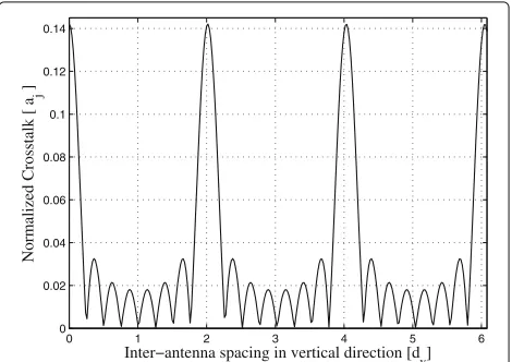
Figure 3 shows the normalized crosstalk versus inter-antenna spacingdy in the vertical direction. In the
sim-ulations, we choose fixed angles corresponding to user positionsθk = θj = π/4,φk = φj = π/4, and the inter-antenna spacing in horizontal direction is set todx=λ/2.
The number of antennas in both horizontal and the verti-cal directions is eight; thus, the total number of antennas
0 1 2 3 4 5 6
0 0.02 0.04 0.06 0.08 0.1 0.12 0.14
Inter−antenna spacing in vertical direction [d
y]
Normalized Crosstalk [ a
j
]
is 8×8=64. We see thatajis a periodic function, due to
the properties of the cos function. To minimize the value of aj, the vertical inter-antenna spacing dy is adjusted
according to the BS size given fixeddx andNt because
the users’ AoDs are not distinguishable in some special scenarios such as a dense region or hot spot.
In order to improve the achievable ergodic SE, we now propose a user scheduling scheme by exploiting azimuth and elevation AoDs of users. The work in [36] has demon-strated that perfect orthogonality between different user channel vectors does exist for ULA and URA configura-tions under LoS propagation condiconfigura-tions. Herein, we only consider the URA configuration in the paper since ULA configuration is a special of the URA configuration.
3.2 Maximum and minimum achievable SE
Although Theorems 1 and 2 provide a result on the achievable ergodic SE, reducing the normalized crosstalk to zero is difficult in a practical system with finite antenna elements. To improve the achievable ergodic SE under MRT precoding, we propose a user scheduling scheme by exploiting users’ AoD information. User scheduling is well recognized as a promising technique to improve the system performance in communication systems. If per-formed effectively, then user scheduling can be an attrac-tive solution to mitigate interference [37, 38]. In mmWave MIMO systems, the steering vector is predominant and the users’ AoD changes slowly [10, 11]. Therefore, our user scheduling scheme shall use the information of the steer-ing vectors to determine a set of users with low crosstalk coefficients. The user scheduling scheme can be outlined as follows:
• The scheduler acquires AoD information of the users and according to the acquired AoD information, the users satisfying the orthogonal criterion are selected as the scheduled group. The specific process is that the AoD information is firstly estimated at mobile stations by using the estimated algorithm (such as multiple signal classification (MUSIC), estimation of signal parameters via rotational invariance
techniques (ESPRIT), and subspace algorithms [10, 39]) and then fed back to BS via feedback of downlink channel. In closed-loop frequency division duplex (FDD) MIMO system, downlink AoD information is usually fed back to BS in forms of codebook or channel quality indicator (CQI)[40, 41]. • According to (42), if the steering vectors satisfy the
orthogonal criterion for given an arbitrary finite number of BS antennas, then
cos(Nxk0dxδx)=1 or/and cos(Nyk0dyδy)=1. (43)
As a result, we have the following conditions forδx andδy, respectively
Nxdxδx
λ =nxor/and Nydyδy
λ =ny, (44)
wherenxandnyare any positive numbers. From (43), we obtain the conditions for the orthogonal criterion as follows:
Nxηsinθkcosφk−sinθjcosφj=nx, (45) or/and
Nyηsinθksinφk−sinθjsinφj=ny. (46) whereηis defined in (4).
• The BS transmits data streams to selected users with equal power allocation.
Remark 1The conditions in (45) and (46) guarantee
that the users in the selected setSare mutually orthogonal. Combined with the user scheduling, the MRT precoding is able to obtain a similar performance to the ZF precod-ing for the reason that the selected user interferences have been completely canceled. Finally, note that our proposed scheduling method focuses on maximizing the achievable ergodic SE; however, in doing so, the fairness among the users is not guaranteed.
We now analyze the asymptotic performance of the proposed scheduling method.
Proposition 1When a set of selected users are mutually orthogonal based on the user scheduling scheme, the inner product of the steering vectors between different links tends to zero. Therefore, the maximum achievable ergodic SE of the system can be expressed as
Rmaxk =log2(e)eρgkNt1 E1
1
ρgkNt
. (47)
Proof The set of selected users are orthogonal to each other. Hence, the achievable ergodic SE of the proposed scheduling scheme is given by
Rmaxk =E
⎧ ⎪ ⎨ ⎪ ⎩log2
⎛ ⎜
⎝1+ρgkhHkwk2
! "# $
Z
⎞ ⎟ ⎠ ⎫ ⎪ ⎬ ⎪
⎭. (48)
We note that the probability density function (pdf ) of the random variableZis given by
fZ(z)=
1
Nt
e−Ntz . (49)
With (49) in hand, we can evaluateRmaxk as
Rmaxk =
& ∞
0
log21+ρgkz
Substituting the pdf ofZinto (50) and with the help of ([27], Eq. (4.337.2)), we obtain
Rmaxk = −log2(e)e
Remark 2From Proposition 1, we observe that the
achievable ergodic SE of MRT precoding with the user scheduling method is identical to that of the ZF precoding
[42]. This is because the MRT transmission scheme with the scheduling criterion in Proposition1 facilitates inter-user interference cancelation. In addition, compared to the ZF precoding, the MRT precoding enjoys a much lower computational complexity and does not involve matrix inverse calculations, whereas the user scheduling scheme described above emphasizes the importance of selecting users for multi-user mmWave MIMO systems.
Corollary 1For the special case of Nt→ ∞orρ→ ∞, the achievable SE reduces to a function with the number of BS antennas and the SNR as follows:
lim
ProofAs the number of antennas or the SNR grows without bound, i.e.,Nt→ ∞, orρ→ ∞, we have
1
ρNt →
0. (53)
By utilizing the following identity for the exponential integral function given in ([43], Eq. (06.34.06.0007.01), whenz→0, we get
E1(z)∝ −ln(z)+O(1). (54)
By making the number of BS antennas and the SNR grow without bound, and performing by some basic alge-braic manipulations, we prove the result.
From Corollary 1, we see that in the high SNR regime, MRT precoding with orthogonal user scheduling not only reduces the consumption of transmit power but also ensures a high achievable ergodic SE. More impor-tantly, the MRT scheme with user scheduling only needs a small number of channel feedback bits to perform near-ideal interference cancelation because the steering vectors become deterministic. These observations clearly reveal the effectiveness of user scheduling.
We now focus on a dense user deployment. In a dense user scenario, e.g., conference hall, railway station, air-plane, or subway entrances, many devices could be
active within close proximity [44]. When users are co-located, the users’ AoDs shall become nearly identical. This extreme case introduces very high inter-user interfer-ence. In the following proposition, we analyze this specific case and evaluate the minimum achievable ergodic SE of the system.
Proposition 2When the users are co-located, the inner product of the steering vectors achieves its maximum value,
i.e., aj=vHj vj
2
/vj2≈Nt, then the minimum achievable ergodic SE is given by
Rmink =log2(e)e
ProofLet us begin by rewriting the achievable ergodic SE in (19) as For the sake of simplicity, we define
S= Z
Conditioning onV, the pdf ofScan be written as
fS(s)=
& ∞
0
fS|V (s|v)fV(v)dv. (60)
Substituting the pdf ofVin (59) into (60), we have
With the help of the integration identity ([27], Eq. (3.310)) and ([27], Eq. (3.381.4)), we obtain
fS(s)= e
− s
ρgkNt
(1+s)K
1
ρgkNt(
1+s)+K−1
. (62)
By calculating the integral in (62), we can easily show that the cdf ofSis given by
FS(s)=1− e−
s
ρgkNt
(1+s)(K−1). (63)
The achievable ergodic SE in (56) can be rewritten as ([45], Eq. (4))
Rmink =log2(e)
& ∞
0
1−FS(s)
1+s ds. (64)
Substituting the cdf ofSin (63) into (64), and with the aid of ([27], Eq. (3.382.4))
& ∞
0
e−bx
(1+x)Ndx=e
bb(N−1) (−N+1,b). (65)
We obtain
Rmink =log2(e)eρgkNt1
1
ρgkNt
K−1
−(K−1), 1
ρgkNt
.
(66)
By applying the identity Eh(x)=xh−1 (1−h,x), we
complete the proof.
From Proposition 2, we draw an interesting conclu-sion that the Rmink is function of the SNR, the number of BS antennas and users. Rmink decreases as the num-ber of users increases. The reason is that EK(·) is a
monotonically decreasing function ofK, and contributes toward increasing the inter-user interference. Therefore, increasing number of users in a dense user scenario can-not benefit the achievable SE. This observation is differ-ent from the case when the number of BS antennas is increased. Clearly, if we do not perform user scheduling, then the achievable SE tends to zero. The following corol-lary presents the impact of the SNR and the number of BS antennas on the downlink achievable SE.
Corollary 2For the special case of Nt→ ∞orρ→ ∞, the minimum achievable SE is reduced to
lim
Nt→∞,orρ→∞R min k =
log2(e)
K−1 . (67)
Proof The proof starts by recalling the properties of
Eh(·)from ([43], Eq. (06.34.03.0002.01)), whenh> 1, we have
Eh(0)= 1
h−1. (68)
For the special case ofNt→ ∞orρ→ ∞, which leads
to 1/(ρgkNt)→ 0. Then, applying the above identity, we
have
EK
1
ρgkNt
= 1
K−1. (69)
Substituting (69) into (55) yields the desired result.
Corollary 2 showcases that the fixed the number of users, Rmink converges to constant as the number of BS antennas grows without bound. This because the co-located users brings high inter-user interference and degrades the performance. Therefore, improving the number of BS antennas and high SNR regime in this scenario cannot contribute to the achievable SE.
4 Numerical results
In this section, we provide simulation results to validate the derived analytical expressions. All simulation results were obtained by averaging over 100,000 independent channel realizations. In our simulations, we adopt the micro cell environment in [33] with slight modifications. The maximum antenna gain at the antenna boresight
Gmax is set to 20 dB, the horizontal and vertical half-power beamwidth φ3dB andθ3dB are set to 65° and 65°, respectively, and the antenna tilting angle θtilt is set to 90°. Furthermore, we assume that the users are randomly distributed in a circular cell. The azimuth and eleva-tion angles of user are randomly drawn from [0, 2π] and [−π/2,π/2] interval, respectively [46]. We select eight users from user grouping, the azimuth and elevation angles of whose are listed in Table 1, and channel vectors are generated according to (3) in Section 3.
In Fig. 4, the simulated total achievable SE for MRT and ZF precoding (MRT with scheduling method), as well as, the derived analytical expressions of Theorem 1 and Proposition 1 are plotted against the SNR. In the simu-lations, the number of BS antennas is set to 8×8=64 and 10×10=100, and the inter-antenna spacing along the horizontal and the vertical direction are set to
dx=dy=λ/2. We see that the theoretical results show a good match with the Monte-Carlo simulations across the entire SNR regime, which validates the analytical results.
Table 1The azimuth and elevation angle of the users(K=8)
U1 U2 U3 U4 U5 U6 U7 U8
φ 0.9681 2.1770 3.0080 1.7151 1.0428 0.7703 0.1790 1.2570
Fig. 4The total achievable SE versus SNR forNt=64, 100 andK=8.
Results are showed for MRT without scheduling method and ZF precoding (MRT with scheduling method)
We also see that for a fixed number of BS antennas and inter-antenna spacing, the total achievable SE for ZF pre-coding increases with the SNR for the reason that the ZF precoding scheme is able to completely cancel out inter-user interference, whereas the total achievable SE for MRT precoding without scheduling method converges to a saturated value in the high SNR regime because the inter-user interference becomes dominant as the SNR increases. Compared with ZF precoding, the total achiev-able SE for MRT precoding without scheduling method is almost identical at SNR = -10 dB, but suffers severe loss (about 200%) at SNR = 30 dB. For comparison, we depict the total achievable SE for different number of antennasNt=64 andNt=100, respectively. We observe that deploying more antennas at the BS always provides additional achievable SE because the large antenna arrays facilitate the asymptotic orthogonal condition between different steering vectors. This observation implies that equipping at the BS with large-scale antenna arrays becomes critical for achieving a good total achievable SE.
Figure 5 depicts the analytical results for the total achievable SE, as well as Monte-Carlo simulation results with different number of BS antennas from 50 to 500. As we can see that the theoretical results remain very tight with the numerical simulation results varies with the number of BS antennas, which validates the theoretical results in Proposition 1. In addition, we also find that with fixed the number of user and the SNR, the total achievable SE grows without bound with the number of BS anten-nas, which is in accordance with the result in Corollary 1. This observation implies that massive antenna arrays con-tribute substantially toward improving the total achiev-able SE, which is especially appealing for mmWave MIMO systems. For comparison, we show the total achievable SE at the different SNR regimes, i.e., 5 and 10 dB. As
50 100 150 200 250 300 350 400 450 500
50 55 60 65 70 75 80 85 90 95
Number of BS antennas [N
t]
Total Achievable SE [bit/s/Hz]
Theoretical Simulation
SNR = 5 dB SNR = 10dB
Fig. 5The total achievable ergodic SE versus the number of BS antennas for SNR = 5 and 10 dB
expected, the achievable SE for the high SNR regime is better than that for the low SNR regime, which is also aligned with the result in Corollary 1.
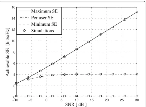
Finally, Fig. 6 shows the simulation and the theoretical results for the maximum achievable ergodic SE with user scheduling, the minimum achievable ergodic SE with a dense user scenario, and the random user’s achievable SE. We observe that in the low SNR regime (e.g.,ρ= −10 dB), the random user’s achievable ergodic SE is almost equal to the case with user scheduling, which slightly increases with the increase in SNR. However, in the high SNR regime, the maximum achievable ergodic SE with the user scheduling method is much greater than that for the ran-dom user selection. Moreover, the maximum achievable ergodic SE shows a linear increase, which is in agree-ment with Corollary 1. The minimum achievable ergodic
−100 −5 0 5 10 15 20 25 30
2 4 6 8 10 12 14 16
SNR [ dB ]
Achievable SE [bit/s/Hz]
Maximum SE Per user SE Minimum SE Simulations
SE is almost constant in the high SNR regime due to severe interference among users, which is in good agree-ment with the theoretical analysis in Corollary 2. This is because as the SNR grows, inter-user interference will also increase.
5 Conclusions
This paper investigated the achievable ergodic SE of the downlink of single-cell multi-user mmWave systems, where the BS is equipped with a large number of trans-mit antennas and service multiple single-antenna users. An exact analytical expression for the achievable ergodic SE was derived. Results showed that the total achievable SE converges to a saturation value in the high SNR regime and increase remarkably in the large antenna regime. For finite number of antennas at the BS, we designed a user scheduling scheme based on users’ AoD infor-mation, and then derived the corresponding maximum achievable ergodic SE. Under this scheduling scheme, the total achievable SE with MRT precoding can be substan-tially improved. Furthermore, we presented the minimum achievable ergodic SE of a system based on a dense user case.
Endnotes
1Note that although a uniform circular array configura-tion can also achieve 3D beamforming, channel steering vectors between different users do not achieve orthogo-nality with a large number of antennas [36].
2Note that for randomly distributed users in the circular-shaped cell, the condition φk = φj holds with probability one.
3The AoDs of the azimuth and elevation angles of the users can be obtained by the BS, and can be treated as constants over a long period [10].
4Given a UCA configuration, crosstalk coefficient ac j
can be expressed by
acj =J02(k0rδc), (70)
whereδc=
'
sin2θk+sin2θj−2 sinθksinθjcosφk−φj, and r denotes the radius of the circular transmit array. Given a ULA configuration, crosstalk coefficient alj can be expressed as
alj = 1 Nt
sin
Nxk0dx
2 δ
sin
k0dx
2 δ
2
, (71)
whereδ=cosφk−cosφj.
Acknowledgements
We would like to thank the anonymous reviewers for their insightful comments on the paper, as these comments led us to an improvement of the work.
Funding
This work was supported by the National Natural Science Foundation of China under Grant 61531011, the International Science and Technology Cooperation Program of China under Grant 2014DFT10300, and the Guangzhou university project under Grant 27000503123.
Authors’ contributions
SJ conceived and designed the idea. WT performed the experiments and analyzed the data. CW and TJ gave valuable suggestions on the structuring of the paper and assisted in the revising and proofreading. All authors read and agreed the manuscript.
Competing interests
The authors declare that they have no competing interests.
Author details
1School of Computer Science and Educational Software, Guangzhou
University, Guangzhou 510006, People’s Republic of China.2National Communications Research Laboratory, Southeast University, Nanjing 210096, People’s Republic of China.3Institute of Communications Engineering, National Sun Yat-sen University, Kaohsiun, 804 Taiwan, People’s Republic of China.4Wuhan National Laboratory for Optoelectronics, School of Electronics Information and Communications, Huazhong University of Science and Technology, Wuhan 430074, People’s Republic of China.
Publisher’s Note
Springer Nature remains neutral with regard to jurisdictional claims in published maps and institutional affiliations.
Received: 10 March 2017 Accepted: 18 October 2017
References
1. F Boccardi, RW Heath Jr., A Lozano, TL Marzetta, P Popovski, Five disruptive technology directions for 5G. IEEE Commun. Mag.52(2), 74–80 (2014) 2. W Roh, J Seol, J Park, B Lee, J Lee, Y Kim, J Cho, K Cheun, Millimeter-Wave
beamforming as an enabling technology for 5G cellular communications: Theoretical feasibility and prototype results. IEEE Commun. Mag.52(2), 106–113 (2014)
3. S Yong, C Chong, An overview of multigigabit wireless through millimeter wave technology: potentials and technical challenges.EURASIP. J. Wireless Commun. Net.7(1), 50–60 (2006) 4. Z Pi, F Khan, An introduction to millimeter-wave mobile broadband
systems. IEEE Commun. Mag.49(6), 101–107 (2011)
5. TL Marzetta, Noncooperative cellular wireless with unlimited numbers of base station antennas. IEEE Trans. Wireless Commun.9(11), 3590–3600 (2010)
6. F Rusek, D Persson, BK Lau, EG Larsson, TL Marzetta, O Edfors, F Tufvesson, Scaling up MIMO: opportunities and challenges with very large arrays. IEEE Signal Process. Mag.30(1), 40–60 (2013)
7. H Ngo, E Larsson, T Marzetta, The multicell multiuser mimo uplink with very large antenna arrays and a finite-dimensional channel. IEEE Trans. Commun.61(6), 2350–2361 (2013)
8. Q Zhang, S Jin, KK Wong, HB Zhu, Power scaling of uplink massive MIMO systems with arbitrary-rank channel means. IEEE J. Sel. Topics Signal Process.57(3), 841–849 (2014)
9. Y Nam, B Ng, K Sayana, Y Li, J Zhang, Y Kim, J Lee, Full-dimension MIMO (FD-MIMO) for next generation cellular technology. IEEE Commun. Mag.
21(2), 172–179 (2013)
10. L Liu, Y Li, J Zhang, inProc. IEEE Int. Conf. Signal Proc. Advances in, Wireless Commun. (SPAWC). DoA estimation and achievable rate analysis for 3D millimeter wave massive MIMO systems, (Toronto, 2014), pp. 6–11 11. S Rangan, TS Rappaport, E Erkip, Millimeter wave cellular wireless
12. J Brady, N Behdad, A Sayeed, Beamspace MIMO for millimeter-wave communications: system architecture, modeling, analysis, and measurements. IEEE Trans. Ant. and Prop.61(7), 3814–3827 (2013) 13. MR Akdeniz, Y Liu, MK Samimi, S Sun, S Rangan, TS Rappaport, Millimeter
wave channel modeling and cellular capacity evaluation. IEEE J. Sel. Areas Commun.32(6), 1164–1179 (2014)
14. J Seo, Y Sung, G Lee, D Kim, inProc. IEEE Int. Conf. Signal Proc. Advances in Wireless Commun. (SPAWC). Pilot beam sequence design for channel estimation in millimeter-wave MIMO systems: A POMDP framework, (Stockholm, 2015), pp. 236–240
15. A Alkhateeb, O Ayach, G Leus, RW Heath Jr., Channel estimation and hybrid precoding for millimeter wave cellular systems. IEEE J. Sel. Areas Commun. Signal Process.8(5), 831–846 (2014)
16. N Ravindran, N Jindal, HC Huang, inProc. IEEE Global, Telecommun. Conf. (GLOBECOM). Beamforming with finite rate feedback for LOS MIMO downlink channels, (Washington, 2007), pp. 4200–4204
17. X Zhang, A Molisch, S Kung, Variable-phase-shift-based RF baseband codesign for MIMO antenna selection. IEEE Trans. Signal Process.53(11), 4091–4103 (2005)
18. X Li, S Jin, HA Suraweera, J Hou, X Gao, Statistical 3-D beamforming for large-scale MIMO downlink systems over Rician fading channels. IEEE Trans. Commun.64(5), 1529–1543 (2016)
19. A Alkhateeb, J Mo, NG Prelcic, RW Heath Jr., MIMO precoding and combining solutions for millimeter-wave systems. IEEE Commun. Mag.
52(12), 122–131 (2013)
20. W Tan, M Matthaiou, S Jin, X Li, Spectral efficiency of DFT-based processing hybrid architectures in massive MIMO. IEEE Wireless Commun. Lett.6(5), 586–589 (2017)
21. L Fan, R Zhao, F Gong, N Yang, GK Karagiannidis, Secure multiple amplify-and-forward relaying over correlated fading channels. IEEE Trans. Commun.65(7), 2811–2820 (2017)
22. L Fan, X Lei, N Yang, TQ Duong, GK Karagiannidis, Secure multiple amplify-and-forward relaying with cochannel interference. IEEE J. Sel. Topics Signal Process.10(8), 1494–1505 (2016)
23. L Fan, S Zhang, TQ Duong, GK Karagiannidis, Secure switch-and-stay combining (SSSC) for cognitive relay networks. IEEE Trans. Commun.
64(1), 70–82 (2016)
24. X Li, T Jiang, S Cui, J An, Q Zhang, Cooperative communications based on rateless network coding in distributed MIMO systems. IEEE Wireless Commun.17(3), 60–67 (2010)
25. T Bai, RW Heath Jr., Coverage and rate analysis for millimeter wave cellular networks. IEEE Trans. Wireless Commun.14(2), 1100–1114 (2015) 26. L Liang, Y Dai, W Xu, X Dong, inProc. IEEE Int. Conf. Commun. in China
(ICCC). How to approach zero-forcing under RF chain limitations in large mmWave multiuser systems? (Xi’an, 2014), pp. 518–522
27. IS Gradshteyn, IM Ryzhik,Table of integrals, series, and products, 7th edition. (Academic, 2007)
28. AM Sayeed, N Behdad, inProc. IEEE Int. Conf. Commun. (ICC). Beamspace MIMO for high-dimensional multiuser communication at millimeter wave frequencies, (Budapest, 2013), pp. 3679–3684
29. G Lee, Y Sung, M Kountouris, On the performance of random beamforming in sparse millimeter wave channels. IEEE J. Sel. Topics Signal Process.10(3), 1–16 (2016)
30. G Lee, Y Sung, J Seo, Randomly-directional beamforming in
millimeter-wave multi-user MISO downlink. IEEE Trans. Wireless Commun.
15(2), 1086–1100 (2016)
31. TS Rappaport, E Ben-Dor, JN Murdock, Y Qiao,38 GHz and 60 GHz angle-dependent propagation for cellular & peer-to-peer wireless communications, (Ottawa, 2012), pp. 679–684
32. W Tan, S Jin, Wang, Y Huang, inIEEE Wireless Commun. and Networking Conf. (WCNC). Achievable sum-rate analysis for massive MIMO systems with different array configurations, (New Orlean, 2015), pp. 316–321 33. 3GPP TR 36.873 V12.1.0, Study on 3D channel model for LTE,” (2015) 34. NL Johnson, S Kotz, N Balakrishnan,Continuous Univariate Distributions Vol.
1, 2nd Ed. (John Wiley Sons, New York, 1994)
35. G Alfano, A Lozano, AM Tulino, S Verdú, inProc. Int. Symp. Information Theory and, Its Applications (ISITA). Mutual information and eigenvalue distribution of MIMO Ricean channels, (Parma, 2004), pp. 10–13
36. JH Chen, inProc. IEEE Global, Commun. Conf. (GLOBECOM). When does asymptotic orthogonality exist for very large arrays? (Atlanta, 2013), pp. 4146–4150
37. T Yoo, A Goldsmith, On the optimality of multiantenna broadcast scheduling using zero-forcing beamforming. IEEE J. Sel. Areas Commun.
24(5), 528–541 (2006)
38. J Nam, A Adhikary, J Ahn, G Caire, Joint spatial division and multiplexing: opportunistic beamforming, user grouping and simplified downlink scheduling. IEEE J. Sel. Topics Signal Process.8, 876–890 (2014) 39. AL Swindlehurst, T Kailath, Azimuth/elevation direction finding using
regular array geometries. IEEE Trans. Aerospace Electronic Syst.29(1), 145–156 (1993)
40. P Viswanath, DNC Tse, R Laroia, Opportunistic beamforming using dumb antennas. IEEE Trans. Inf. Theory.48(6), 1277–1294 (2002)
41. DJ Love, RW Heath Jr., Limited feedback unitary precoding for spatiall multiplexing systems. IEEE Trans. Inf. Theory.51(8), 2967–2976 (2005) 42. L Liang, W Xu, X Dong, Low-complexity hybrid precoding in massive multiuser MIMO systems. IEEE Commun. Lett.3(6), 653–656 (2014) 43. From Math World-A Wolfram Web Resource. [Online] Available: http://
functions.wolfram.com/PDF/ExpIntegralE.pdf
44. A Adhikary, EA Safadi, MK Samimi, R Wang, G Caire, TS Rappaport, AF Molisch, Joint spatial division and multiplexing for mm-wave channels. IEEE J. Sel. Areas Commun.32(6), 1239–1248 (2014)
45. HA Suraweera, PJ Smith, M Shafi, Capacity limits and performance analysis of cognitive radio with imperfect channel knowledge. IEEE Trans. Veh. Technol.59(4), 1811–1822 (2010)