ISSN 2348 – 7968
646
Interference Cancellation using CoMP for Macro-Pico Cell
Clusters with Cooperative Receiver
Dimpal Jitendrabhai Vyas, Prof. Aslam Durvesh
Electronics and Communication Dept, Parul Institute of Eng.& Tech, Vadodara, Gujarat, India
ABSTRACT
In this paper the discussion on the standard towards 4G in LTE System, which is used for the increasing Throughput and Channel Capacity and also for the SINR. For performance improvement in this paper the Coordinated Multipoint transmission/reception technique is used. The Channel Capacity can be increased in Macrocell as well as Picocell Clusters to dense sets of users in next generation networks. Here consider on the downlink channel and analyze the performance between two clusters with cooperative multi-cell joint decoding. The picocell concept is an emerging technology for deploying the next generation of the wireless networks, Nevertheless, one of the most critical issues is the interference between picocell and macrocells or to mobile handsets, thus decreasing the overall system capacity. In this paper, the Macro-pico scenario in OFDMA based Networks is evaluated and with the use of coordinated multipoint
technique the improvement in the performance
throughput by applying CoMP. Simulation results show that the discussed schemes are able to significantly reduce the interference so that improve the throughput as well as spectral efficiency and SINR.
KEY WORDS: LTE, C o o r d i n a t e d M u l t i p o i n t t r a n s m i s s i o n , OFDMA, picocell, Partial Cluster cancellation, Full cluster cancellation .
INTRODUCTION
Long Term Evolution(LTE) is the latest standard in the mobile network technology IN 3GPP.The main goal of LTE is to provide a high data rate, low latency and packet optimized radio access technology.LTE is Important because it will bring up to 50 times performance improvement and much better spectral efficiency to cellular networks.
The downlink access is based on multi carrier frequency division multiple access (OFDMA) that promises increased downlink coverage by using CoMP technique. For downlink higher data rates,300 Mbps by using 20MHz Carrier. In OFDMA [3][ system, the spectrum is divided to a large number of sub carriers. Since those sub-carriers are orthogonal with each other, there is no intra cell
interference. H e r e i n F i g . 1 UE is under a coverage of a femto or pico cell. In this case, the Macro cells around those pico/femto cell or other pico/femto cell can act as interferer. In this case, the signal strength from serving cell may not be such a weak, but SNR tend to be poorer due to the interference.S o d e c r e a s i n g t h e i n t e r f e r e n c e , h e r e t h e C o M P T e c h n i q u e i s u s e d [ 2 ] . The main benefit of these small base stations is the improved indoor coverage and offloading of traffic from macro base stations.
ISSN 2348 – 7968
647
Fig. 1 Downlink interference scenarios in an integrated pico/macrocell environment[6]
This paper examines the challenge of optimizing SINR, and discusses various strategies to enhance the performance of Throughput using the CoMP technique by the existing LTE standard. In this paper, we proposed for downlink Centralized/Autonomous Deecentralized control and also Joint and dynamic transmission. In Centralized control the remote processor is at centre and control the system.and in Decentralized control there is direct communication between two networks. And in Joint transmission the signal strength is higher the UE access the data from the two networks, in Dynamic transmission there is a choice for the UE that the UE can access the data.
INTRODUCTION AND TECHNICAL CHALLENGES OF LTE HETEROGENEOUS NETWORKS
HetNet (Heterogeneous Networks) consists of mix of macrocells, radio heads and low power nodes like picocells, femtocells and relays - "A new paradigm to increase the cellular capacity and coverage". Spatial reuse and capacity improvement by leveraging the network topology existing today between the wireless networks and Users results in obvious technical challenges: when smaller cells are deployed over macrocells.
In a HetNet architecture, in addition to usual macro cells, wireless access is also provided through low- powered and low-cost radio access nodes that have coverage radius around 10 m-300 m [3]. Table 1 shows different types of HetNet access Nodes in LTE
ISSN 2348 – 7968
648
The concept of HetNet and its technical challenges, standardization activities relating to enhanced inter cell interference coordination would be focused.
Table 1 Specification of Different Elements in HetNet[4].
Types of
Nodes Transmit Power Coverage Backhaul Macrocell 46 dbm Few km S1
Interface Picocell 23-30 dbm <300 m X2
Interface Femtocell <23 dbm <50 m Internet Relay 30 dbm 300 m Wireless RRH 46 dbm Few km Fiber
DIFFERENT FREQUENCY REUSE TECHNIQUES IN LTE HETNETS
There are various schemes used in LTE standard. The Partial cluster cancellation scheme and Full cluster cancellation scheme are described in this paper. These schemes describe the different interference cancellation schemes for cooperative receivers. also a system performance boost can be achieved by managing the system bandwidth and transmit power.
SYSTEM MODEL
In Fig 2 consider two neighboring Pico-cell clusters. Clusters 1 and 2 each have N receive antennas with a load of β1=ଵ and β2=ଶ transmitted streams per
receive antenna respectively.
Fig 2.Two interfering pico-clusters[1]
Y1=H1X1+αH2intX2+n1
Y2=H2X2+αH1intX1+n2
Where the single parameter 0≤α≤1 represents the attenuation.
A Partial Cluster cancellation:
Fig 3:Partial and Full Cluster Cancellation Scheme[1]
From this above fig.3 the concept is that in PCC,the two clusters first exchange the decoded symbols of group A and subsequently decode Group B users after interference cancellation.In this scheme the parameters which are used are(β,θ,λ).
[PCC Phase 1]: Each cluster decodes its Group A Of λi βi N users using a linear MMSE receiver and
forwards the decoded symbols to the neighboring cluster for interference cancellation[8].
[PCC Phase 2]: Each cluster decodes the (1-λi) βi N
users in Group B after cancelling the interference from users in Group A.
B Full Cluster Cancellation:
Another message passing scheme in which one of the Clusters decode all users within the cluster, and passes the messages to the RCP for the adjacent cluster for interference cancellation[8].
SIMULATION
We consider Heterogeneous networks consisting of macrocells and Picocells. Picocell BSs which have uniform separation with one another are densely deployed within a macrocell. We use the Wiener Channel Model [6] for communication between two networks.
Plossout[dB] = 31.81 + 40.5 ݈݃10(d[m]) + Xαout...1
In equation 1 Where d is the distance between sender and receiver and Xαout represents the shadowing
ISSN 2348 – 7968
649
distribution with zero mean and standard deviation (αout)[5].
The overall Network is assumed to be composed of N adjacent cells. Each cell contains a number of users seeking to share a group of subcarriers.
The case where a user is found in the centre of the cell or in the edge is determined. In a typical LTE network, for a user u who is served by a Base Station bs on subcarrier n, the related SINR is given by the following equation[5].
ܲܮܾݏ ,ݑ ܾܲܶݏ ,݊ ܪܾݏ ,ݑ ,݊
SINRu,n = ………2
ߪ݊2+Σ
jk ܲܮ, , ܪ݆ ,ݑ ,݊
In Equation 2, PLbs,u refers to the path loss between
user u and the Base Station bs, PTbs,n is the transmit
power of the Base Station on subcarrier n, Hbs,u,n is the exponentially distributed channel fast fading power and ߪn is the noise power of an Additive White Gaussian Noise (AWGN) channel. [5]Symbols k and j refer to the set of all the interfering Base Stations (i.e.Base Stations that are using the same sub-band as User u). Their physical meaning is that j is the cell index and k the number of co-channel cells.In our analysis, we assume that equal Performance Enhancement of LTE Heterogeneous Networks transmit power is applied (PTbs,n = P), for all Base Stations. The coefficient Hbs,u,n is replacedby its mean value (Hbs,u,n = 1).
Fig 4. UEs Wideband SINR [dB]
Fig 4 Indicates the difference of the SINR between Picocell and macrocell and observed that the picocell clusters SINR is higher compared to the Macrocell
ISSN 2348 – 7968
650
The SINR Calculation is basically done by the above equation for the graph.
Fig 5. UEs Average Throughput[MBPS]
Fig5 Indicates the difference of the Average Throughput between the Picocell and macrocell and observed that the picocell clusters Average Throughput is higher compared to the Macrocell clusters.
The Calculation of Throughput in this Fig. is based on following equation 3 and 4. The Capacity of User u on Subcarrier n can be calculated from the following equation[5]
C
u,nf log
2(1 SINR
u,n)
...3TH
u= n
β
u,n. C
……...……….4Where, βu,n represents the subcarrier assigned to user u.
Fig 6 .UEs Average Spectral Efficiency[bits/cu]
Fig 6. Indicates the UEs Average Spectral efficiency in picocell and Macrocell. The Spectral Efficiency is higher in picocell compared to the Macrocell.
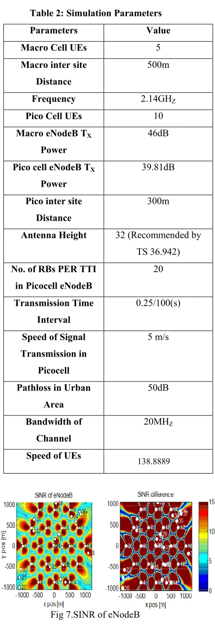
Table 2: Simulation Parameters
Parameters Value Macro Cell UEs 5
Macro inter site Distance
500m
Frequency 2.14GHZ Pico Cell UEs 10
Macro eNodeB TX
Power
46dB
Pico cell eNodeB TX
Power
39.81dB
Pico inter site Distance
300m
Antenna Height 32 (Recommended by TS 36.942)
No. of RBs PER TTI in Picocell eNodeB
20
Transmission Time Interval
0.25/100(s)
Speed of Signal Transmission in
Picocell
5 m/s
Pathloss in Urban Area
50dB
Bandwidth of Channel
20MHZ
Speed of UEs 138.8889
ISSN 2348 – 7968
651
Fig 8: Max. SINR (macroscopic fading)
Fig 9: SINR difference limited to 15dB (macroscopic fading)
Conclusions:
When having a different types of Networks deployment, interference between the different base stations (Macro-Pico) may become a problem for their successful operation. With the use of Coordinated Multipoint Transmission Technique can be reduce Interference and improve performance of LTE Heterogeneous Networks. As shown Fig. 4 SINR Comparison of Macro eNodeB and pico eNodeB users, and the conclusion is that pico eNodeB user has higher SINR[dB]compare to the Macro eNodeB users. Same scenario is displaying in Fig. 5 where the Throughput comparison is between Pico and Macrocell and the Average Throughput[Mbps] is Higher in picocell compare to the Macrocell. Based on the performance shown in the Fig.6 the Spectral Efficiency is higher in picocell compared to the Macrocell. In order to maximize cell/user throughput[Mbps], SINR[dB],Spectral Efficiency [bits/cu] and channel capacity can be improved in picocell by using CoMP technique and it should be also reduce interference in Macro-Pico clusters.
REFERENCES
[1]Khalid Zeineddine, Michael Honig,Shrirish Nagraj and Philip Fleming, “Performance of Picocell clusters with Cooperative Receivers”,Globecom 2012-Communication Theory Symposium,Evanston,IL 60208,pp2426-2431.
[2]Chang-Yeong Oh, Min Young Chung, Hyunseung Choo, and Tae-Jin Lee, “A Novel Frequency Planning for picocells in OFDMA-Based Cellular Networks Using CoMP”, ICCSA, Part III, LNCS 6018, pp. 96–106, 2010.
[3]Chrysovalantis Kosta, Bernard Hunt, Atta UI Quddus, and Rahim Tafazolli, “On Interference Avoidance through Interference Cancellation Based on OFDMA Mobile Systems”, IEEE Communications Surveys & tutorials, VOL. 15, NO. 3, third quarter 2013
[4]David Lopez-Perez1, Ismail Guvenc, Guillaume de la Roche, Marios Kountouris, Tony Q.S. Quek, Jie Zhang, “Enhanced Inter-Cell Interference Coordination Challenges in Heterogeneous Networks”, IEEE Wireless Commun. Mag., vol. 18, no 3, Page(s):22 - 30, 2011
[5]Dimitrios Bilios, Christos Bouras, Vasileios Kokkinos, Andreas Papazois, Georgia Tseliou (2012). "Optimization of Fractional Frequency Reuse in Long Term Evolution Networks", wireless communication and networking conference, IEEE.
[6]Shirish Nagraj, M R Raghvendra, Philip J. Fleming,Michael Honig, “Multi-cell Distributed Interference Cancellation for Co-operative Picocell clusters”, Globecom 2012-wireless communication symposium Arlington Heights,IL 60004,pp 4193-4199.
[7]E.Dalhman,s. Parkvall, and J.Skold, 4G LTE/LTE-Advanced for Mobile Broadband.Elsevier,2011.
[8]S.Khattak,W.Rave,and G.Fettweis, “Distibuted iterative multiuser detection through base station cooperation,”EURASIPJ.Wirel.Commun.Netw.vol.2008,
![Fig. 1 Downlink interference scenarios in an integrated pico/macrocell environment[6]](https://thumb-us.123doks.com/thumbv2/123dok_us/7828306.1297163/2.612.80.297.111.312/fig-downlink-interference-scenarios-integrated-pico-macrocell-environment.webp)
![Table 1 Specification of Different Elements in HetNet[4].](https://thumb-us.123doks.com/thumbv2/123dok_us/7828306.1297163/3.612.75.299.528.672/table-specification-different-elements-hetnet.webp)
![Fig 4. UEs Wideband SINR [dB]](https://thumb-us.123doks.com/thumbv2/123dok_us/7828306.1297163/4.612.68.304.487.641/fig-ues-wideband-sinr-db.webp)