Adaptive Technique For Test Packet Generation
*B.MADHURI **K.GOUTHAM RAJU
*M.TECH Dept of CSE,VAAGDEVI COLLEGE OF ENGINEERING
**Assistant Professor Dept of CSE, VAAGDEVI COLLEGE OF ENGINEERING
Abstract—
Recently networks are growing wide and
more complex. However administrators use
tools like ping and trace route to debug
problems. Hence we proposed an automatic
and Methodical approach for testing and
debugging networks called Automatic Test
Packet Generation (ATPG). This approach
gets router configurations and generates a
device-independent model. ATPG generate
a few set of test packets to find every link in
the network. Test packets are forwarded
frequently and it detect failures to localize
the fault. ATPG can detect both functional
and performance (throughput, latency)
problems. We found, less number of test
packets is enough to test all rules in
networks. For example, 4000 packets can
cover all rules in Stanford backbone
network, while 53 are much enough to cover
all links.
Keywords: Fault Localization, Test Packet
Selection, Network Debugging, Automatic
Test packet Generation (ATPG), Forwarding
Information Base (FIB).
1.INTRODUCTION
It is popularly known us, very difficult to
troubleshoot or identify and remove errors in
networks. Every day, network engineers
fight with mislabeled cables, software bugs,
router misconfigurations, fiber cuts, faulty
interfaces and other reasons that cause
networks to drop down. Network engineers
hunt down bugs with various tools (e.g.,
Ping, trace route, SNMP) and track down
the reason for network failure using a
combination of accrued wisdom and
impression. Debugging networks is
becoming more harder as networks are
growing larger (modern data centers may
contain 10 000 switches, a campus network
may serve 50 000 users, a 100-Gb/s
long-haul link may carry 100 000 flows) and are
getting complicated (with over 6000 RFCs,
router software was based on millions of
lines of source code, and network chips
contain billions of gates. Fig. 1 is a
simplified view of network state. Bottom of
each packet, consist of L2 and L3
forwarding information base (FIB), access
control lists, etc. The forwarding state was
written by the control plane (that could be
local or remote) and should correctly
implement the network administrator’s
scheme. Examples of the scheme include:
―Security group X was isolated from security Group Y,‖ ―Use OSPF for routing,‖ and ―Video traffic received at least 1 Mb/s.‖
We could think of the controller compiling
the scheme (A) into devicespecific
configuration files (B), which in turn
determine the forwarding behavior of each
packet (C). To ensure the network behave as
designed, the three steps should remain
consistent every times. Minimally, requires
that sufficient links and nodes are working;
the control plane identifies that a laptop can
access a server, the required outcome can
fail if links fail. The main reason for
network failure is hardware and software
failure, and this problem is recognized
themselves as reach ability failures and
throughput/latency degradation.ATPG
detects errors independently and
exhaustively testing forwarding entries and
packet processing rules in network. In this
tool, test packets are created algorithmically
from the device configuration files and First
information base, with minimum number of
packets needed for complete coverage.
Test packets are fed into the network in
which every rule was exercised directly
from the data plan. Since ATPG treats links
just like normal forwarding rules, the full
coverage provides testing of every link in
network. It could be particularized to
generate a minimal set of packets that test every
link for network liveness. For reacting to failures, many network operators like Internet proactively test the health of the network by pinging between all pairs of sources. Organizations can modify ATPG to face their needs; for example, they can select to test for network liveness (link cover) or test every rule (rule cover) to make sure security policy. ATPG could be modified to test reachability and performance. ATPG can adapt to constraints such as taking test packets from only a few places in the network or using particular routers to generate test packets from every port.
The contributions of this paper are as
follows:
1) A survey of network operators exposing
common failures and root causes.
3) A fault localization algorithm to separate
faulty devices and Rules.
4) ATPG usecases for functional and
throughput testing.
5) Evaluation of prototype ATPG system
using rulesets gathered from the Stanford
and Internet2 backbones.
II.
CURRENT PRACTICE
To understand the problems network
engineers encounter, and how they currently
troubleshoot them, we invited subscribers to
the NANOG1 mailing list to complete a
survey in May–June 2012. Of the 61 who
responded, 12 administer small networks (
<1k hosts), 23 medium networks (1 k–10
>100 k hosts), 11 large networks (10 k–100
k hosts), and 12 very large networks (k
hosts). All responses (anonymized) are
reported in [33] and are summarized in
TABLE I.
Causes: The two most common symptoms
(switch and router software bugs and
hardware failure) are best found by dynamic
testing.
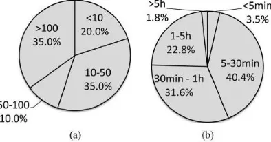
Cost of troubleshooting: Two metrics
capture the cost of network debugging—the
number of network-related tickets per month
and the average time consumed to resolve a
ticket (Fig. 2). There are 35% of networks
that generate more than 100 tickets per
month. Of the respondents, 40.4% estimate
it takes under 30 min to resolve a ticket.
However, 24.6% report that it takes over an
hour on average. Tools: Table II shows that ,
, and SNMP are by far the most popular
tools. When asked what the ideal tool for
network debugging would be, 70.7%
reported a desire for automatic test
generation to check performance and
correctness. Some added a desire for ―long
running tests to detect jitter or intermittent
issues,‖ ―real-time link capacity
monitoring,‖ and ―monitoring tools for network state.‖ In summary, while our
that network administrators face
complicated symptoms TABLE II TOOLS
USED BY NETWORK DMINISTRATORS
( MOST OFTEN; LEAST OFTEN) and
causes. The cost of debugging is nontrivial
due to the frequency of problems and the
time to solve these problems. Classical tools
such as and are still heavily used, but
administrators desire more sophisticated
tools.
III. NETWORK MODEL
ATPG uses the header space framework—a
geometric model of how packets are
processed we described in [16] (and used in
[31]). In header space, protocol-specific
meanings associated with headers are
ignored: A header is viewed as a flat
sequence of ones and zeros. A header is a
point (and a flow is a region) in the space,
where is an upper bound on header length.
By using the header space framework, we
obtain a unified, vendor-independent, and
protocol-agnostic model of the network2
that simplifies the packet generation process
significantly.
A. Definitions Fig.
3 summarizes the definitions in our model.
Packets:
A packet is defined by a tuple, where the
denotes a packet’s position in the network at
any time instant; each physical port in the
network is assigned a unique number.
Switches:
A switch transfer function, models a
network device, such as a switch or router.
Each network device contains a set of
forwarding rules (e.g., the forwarding table)
that determine how packets are processed.
An arriving packet is associated with exactly
one rule bymatching it against each rule in
descending order of priority, and is dropped
if no rule matches.
Rules:
A rule generates a list of one or more output
packets, corresponding to the output port(s)
to which the packet is sent, and defines how
packet fields are modified. The rule
abstraction models all real-world rules we
know including IP forwarding (modifies
port, checksum, and TTL, but not IP
address); VLAN tagging (adds VLAN IDs
to the header); and ACLs (block a header, or
and causes. The cost of debugging is
nontrivial due to the frequency of problems
and the time to solve these problems.
Classical tools such as and are still heavily
used, but administrators desire more
sophisticated tools To send and receive test
packets, network monitor assumes special
test agents in the network. The network
monitor gets the database and builds test
packets and instructs each agent to send the
proper packets. Recently, test agents
partition test packets by IP Proto field and
TCP/UDP port number, but other fields like
IP option can be used. If any tests fail, the
monitor chooses extra test packets from
booked packets to find the problem. The
process gets repeated till the fault has been
identified. To communicate with test agents,
monitor uses JSON, and SQLite’s string
matching to lookup test packets efficiently
ATPG uses the header space framework—a
geometric model of how packets are
processed we described in [16] (and used in
[31]). In header space, protocol-specific
meanings associated with headers are
ignored: A header is viewed as a flat
sequence of ones and zeros.
A header is a point (and a flow is a region)
in the space, where is an upper bound on
header length. By using the header space
framework, we obtain a unified,
vendor-independent, and protocol-agnosticmodel of
the network2 that simplifies the packet
generation process significantly. models all
real-world rules we know including IP
forwarding (modifies port, checksum, and
TTL, but not IP address); VLAN tagging
(adds VLAN IDs to the header); and ACLs
(block a header, or map to a queue).
Essentially, a rule defines how a region of
header space at the ingress (the set of
packets matching the rule) is transformed
into regions of header space at the egress
connected by links. Links are rules that
forward packets from to without
modification. If no topology rules match an
input port, the port is an edge port, and the
packet has reached its destination. B. Life of
a Packet The life of a packet can be viewed
as applying the switch and topology transfer
functionsrepeatedly (Fig. 4). When a packet
function that contains the input port is
applied to , producing a list of new packets .
If the packet reaches its destination, it is
recorded. Otherwise, the topology function
is used to invoke the switch function
containing the new port. The process repeats
until packets reach their destinations (or are
dropped).
IV. ATPG SYSTEM
Based on the network model, ATPG
generates the minimal number of test
packets so that every forwarding rule in the
network is exercised and covered by at least
one test packet.When an error is detected,
ATPG uses a fault localization algorithm to
determine the failing rules or links. Fig. 5 is
a block diagram of theATPG system. The
system first collects all the forwarding state
from the network (step 1). This usually
involves reading the FIBs, ACLs, and
configfiles, as well as obtaining the
topology. ATPG uses Header Space
Analysis [16] to compute reachability
between all the test terminals (step 2). The
result is then used by the test packet
selection algorithm to compute a minimal
set of test packets that can test Fig. 5. ATPG
system block diagram. all rules (step 3).
These packets will be sent periodically by
the test terminals (step 4). If an error is
detected, the fault localization algorithm is
invoked to narrow down the cause of the
error (step 5). While steps 1 and 2 are
described in [16], steps 3–5 are new.
A. Test Packet Generation 1
Algorithm:
We assume a set of test terminals in the
network can send and receive test packets.
Our goal is to generate aset of test packets to
exercise every rule in every switch function,
so that any fault will be observed by at least
one test packet. This is analogous to
software test suites that try to test every
possible branch in a program. The broader
goal can be limited to testingevery link or
every queue. When generating test packets,
ATPG must respect two key constraints:
1) Port: ATPG must only use test terminals
that areavailable;
2)Header: ATPGmust only use headers that
each test terminal is permitted to send. For
example, the network administrator may
only allow using a specific set of VLANs.
Formally, we have the following problem.
Problem 1 (Test Packet Selection): For a
network with the switch functions, , and
topology function, determine the minimum
rules, subject to the port and header
constraints. ATPG chooses test packets
using an algorithm we call Test Packet
Selection (TPS). TPS first finds all
equivalent classes between each pair of
available ports. An equivalent class is a set
of packets that exercises the same
combination of rules. Here, test packets are
generated algorithmically from device
configuration files and from FIBs, which
requires minimum number of packets for
complete coverage.
Test packets are fed into the network in
which that every rule is covered directly
from the data plane. Since ATPG treats links
like normal forwarding rules, its full
coverage provides testing of every link in
the network. It can also be specialized to
form a minimal set of packets that obviously
test every link for network liveness.
B. Life of a Packet
The life of a packet can be viewed as
applying the switch and topology transfer
functions repeatedly (Fig. 4). When a packet
arrives at a network port , the switch
function that contains the input port is
applied to producing a list of new packets .
If the packet reaches its destination, it is
recorded. Otherwise, the topology function
is used to invoke the switch function
containing the new port. The process repeats
until packets reach their destinations (or are
dropped) first finds all equivalent classes
between each pair of available ports. An
equivalent class is a set of packets that
exercises the same combination of rules.
Here, test packets are generated
algorithmically from device configuration
files and from FIBs, which requires
minimum number of packets for complete
coverage.
Test packets are fed into the
network in which that every rule is covered
directly from the data plane. Since ATPG
treats links like normal forwarding rules, its
full coverage provides testing of every link
in the network. It can also be specialized to
form a minimal set of packets that obviously
test every link for network liveness. B. Life
of a Packet The life of a packet can be
viewed as applying the switch and topology
transfer functions repeatedly (Fig. 4). When
a packet arrives at a network port , the
switch function that contains the input port
is applied to producing a list of new packets
. If the packet reaches its destination, it is
recorded. Otherwise, the topology function
is used to invoke the switch function
containing the new port. The process repeats
until packets reach their destinations (or are
dropped).
V.TYPES OF ATPG
Two types of testing’s, functional and
cases demonstrate.Functional TestingWe
can test the functional correctness of a
network by testingthat every reachable
forwarding and drop rule in the network is
behaving correctly. Forwarding Rule: A
forwarding rule is behaving orrectly if a test
packet exercises the rule and leaves on the
correct port with the correct header
Link Rule:
A link rule is a special case of a orwarding
rule. It can be tested by making sure a test
packet passes correctly over the link without
header modifications. Drop Rule: Testing
drop rules is harder because we must verify
the absence of received test packets. We
need to know which test packets might reach
an egress test terminal if a drop rule was to
fail. To find these packets, in the all-pairs
reachability analysis, we conceptually ―flip‖
each drop rule to a broadcast rule in the
transfer functions. We do not actually
change rules in the switches—we simply
emulate the drop rule failure in order to
identify all the ways a packet could reach
the egress test terminals. If the drop rule was
instead a broadcast rule, it would forward
the packet to all of its output ports, and the
test packets would reach Terminals 2 and 3.
Now, we sample the resulting equivalent
classes as usual:We pick one sample test
packet from A ^ B and one from A^C . Note
that we have to test both A^ b and A^C
because the drop rule may have failed R2 at
, resulting in an unexpected packet to be
received at either test terminal 2(A^C) or
test terminal 3 . Finally, we send and expect
the two test packets not to appear since their
arrival would indicate a failure of R2’s drop
rule.
Performance Testing
We can also use ATPG to monitor the
performance of links, queues, and QoS
classes in the network, and even monitor
SLAs.
Congestion:
If a queue is congested, packets will
experience longer queuing delays. This can
be considered as a (performance) fault.
ATPG lets us generate one way congestion
tests to measure the latency between every
pair of test terminals; once the latency
passed a threshold, fault localization will
pinpoint the congested queue, as with
regular faults. With appropriate headers, we
problem. Available Bandwidth: Similarly,
we can measure the available bandwidth of a
link, or for a particular service class. ATPG
will generate the test packet headers needed
to test every link, or every queue, or every
service class; a stream of packets with
VI. IMPLEMENTATION
Based on the network model, ATPG
generates the minimal number of test
packets so that every forwarding rule in the
network is check and covered by at least one
test packet. When an error is detected,
ATPG uses a fault localization algorithm to
determine the failing rules or links [1]. Fig.1
is a block diagram of the ATPG system. The
system first collects all the forwarding state
from the network then all below test perform
on network. Step 1- This involves reading
the FIBs, ACLs, and config file, and
obtaining the topology. ATPG uses Header
Space Analysis to compute reach ability
between all the test terminals. Step 2- The
result is then used by the test packet
selection algorithm to compute a minimal
set of test packets that can test ll rules. Step
3 - These packets will be sent periodically
by the test terminals Step 4 - If an error is
erected, the fault localization algorithm is
down the cause of the error.
A general survey of network admin provides
information about common failures and root
causes in network. A fault localization
algorithm is to quarantine faulty devices and
its rules and configurations. ATPG performs
various testing like functional and
performance testing to improve accuracy.
Evaluation of a prototype ATPG system
using rule sets collected from the Stanford
and Internet2 backbones We can think of the
controller compiling the policy (A) into
device-specific configuration files (B),
which in turn determine the forwarding
behavior of each packet (C). To ensure the
net-work behaves as designed, all three steps
should remain consistent at all times i.e. In
addition, the topology, shown to the bottom
right in the figure, should also satisfy a set
of liveness properties. Minimally, requires
that sufficient links and nodes are working;
if the control plane specifies that a laptop
can access a server, the desired outcome can
fail if links fail. Can also specify
performance guarantees that detect flaky
Overhead and performance and
limitations
the offline ATPG calculation less frequently,
this runs the risk of using out-of-date
forwarding information. Instead, we reduce
overhead in two ways. First, we have
recently sped up the all-pairs reachability
calculation using a
astmultithreaded/multimachine header space
library. Second, instead of extracting the
complete network state every time ATPG is
triggered, an incremental state updater can
significantly reduce both the etrieval time
and the time to calculate reachability. We
are working on a real-time version of ATPG
that incorporates both techniques. Test
agents within terminals incur negligible
overhead because they merely demultiplex
test packets addressed to their IP address at a
modest rate (e.g., 1 per millisecond)
compared to the link speeds Gb/s most
modern CPUs are capable of receiving.
Dynamic boxes: ATPG cannot model boxes
whose internalstate can be changed by test
packets. For example, an NAT that
dynamically assigns TCP ports to outgoing
packets can confuse the online monitor as
the same test packet can give different
results. 2) Nondeterministic boxes: Boxes
can load-balance packets based on a hash
function of packet fields, usually combined
with a random seed; this is common in
multipath routing such as ECMP. When the
hash algorithm and parameters are unknown,
ATPG cannot properly model such rules.
However, if there are known packet patterns
that can iterate through all possible outputs,
ATPG can generate packets to traverse
every output.
CONCLUSION
Testing liveness of a network is a
fundamental problem for ISPs and large data
center operators. Sending probes between
every pair of edge ports is neither exhaustive
nor scalable ATPG, however, goes much
further than liveness testing with the same
framework. ATPG can test for reachability
policy (by testing all rules including drop
rules) and performance health (by
associating performance measures such as
latency and loss with test packets). Our
implementation also augments testing with a
simple fault localization scheme also
constructed using the header space
formal model helps maximize test coverage
while minimizing test packets.
REFERENCES
[1] Zeng , Kazemian, Varghese,and Nick
―Automatic Test Packet Generation‖,VOL.
22, NO. 2, APRIL 2014
[2] Y. Bejerano and R. Rastogi, ―Robust
monitoring of link delays and faults in IP
networks,‖ IEEE/ACM Trans Netw., vol.
14, no. 5, pp. 1092–1103, Oct. 2006
[3] N. Duffield, ―Network tomography of
binary network performance
characteristics,‖ IEEE Trans. Inf. Theory,
vol. 52, no. 12, pp. 5373–5388, Dec. 2006.
[4] N. Duffield, F. L. Presti, V. Paxson,
andD.Towsley,―Inferringlink loss using
striped unicast probes,‖ in Proc. IEEE
INFOCOM, 2001, vol. 2, pp. 915–923.
[5] Y. Bejerano and R. Rastogi, ―Robust
monitoring of link delays and faults in IP
networks,‖ IEEE/ACM Trans. Netw., vol.
14, no. 5, pp. 1092–1103, Oct. 2006.
[6] C. Cadar, D. Dunbar, and D. Engler,
―Klee: Unassisted and automatic generation
of high-coverage tests for complex systems
programs,‖ in Proc. OSDI, Berkeley, CA,
USA, 2008, pp. 209–224.
[7] M. Canini,D.Venzano, P.
Peresini,D.Kostic, and J. Rexford, ―A NICE
way to test OpenFlow applications,‖ in Proc.
NSDI, 2012, pp. 10–10.
[8] A. Dhamdhere, R. Teixeira, C. Dovrolis,
and C. Diot, ―Netdiagnoser:
Troubleshooting network unreachabilities
using end-to-end probes and routing data,‖
in Proc. ACM CoNEXT, 2007, pp. 18:1–
18:12..
[9] N. Duffield, ―Network tomography of
binary network performance
characteristics,‖ IEEE Trans. Inf. Theory,
vol. 52, no. 12, pp. 5373–5388, Dec. 2006.
[10] N. Duffield, F. L. Presti, V. Paxson, and
D. Towsley, “Inferring link loss using striped
unicast probes,” in Proc. IEEE INFOCOM,
2001, vol. 2, pp. 915–923.
AUTHOR 1:-
* B.Madhuri completed her B tech in
Ganapathy Engineering College in 2014 and
pursuing M-Tech in Vaagdevi College of
Engineering
AUTHOR 2:-
**K.Goutham Raju is working as
Assistant Professor in Dept of CSE,