Proposed Smart Power Supply (SPS)
Algorithm for Spacecraft System: The CBSS
Eagle UAV as a case study
N. E. Ezechi1,7, O. L Daniyan2,8, N. Aliyu 3,6,9, C. Justus4,10, D. Nwagbara5,11.
Engineer I, Instrumentation Division, NASRDA - Centre for Basic Space Science, University of Nigeria Nsukka,
Enugu, Nigeria1
Assistant Chief Engineer, Instrumentation Division, NASRDA - Centre for Basic Space Science, University of Nigeria
Nsukka, Enugu, Nigeria2
Senior Engineer, Instrumentation Division, NASRDA - Centre for Basic Space Science, University of Nigeria Nsukka,
Enugu, Nigeria3
Engineer I, Instrumentation Division, NASRDA - Centre for Basic Space Science, University of Nigeria Nsukka,
Enugu, Nigeria4
Engineer II, Instrumentation Division, NASRDA - Centre for Basic Space Science, University of Nigeria Nsukka,
Enugu, Nigeria5
Ph.D Student, School of Electrical & Electronics Engineering, Newcastle University, United Kingdom6
ABSTRACT: The design of the power systems of most Unmanned Aerial Vehicles (UAV) often comprise of a unilateral power server. The source is mostly a chemical energy that serves all the energy demand for the spacecraft. This energy goes a long way in determining the flight duration of the vehicle. The performance of such spacecraft could be improved with the introduction of alternating power server(s) in the system's design such as solar power server or source. In this work, we propose a Smart Power Supply (SPS) algorithm which can schedule and manage the services of these power servers on-board the UAV. This algorithm probes the energy integrity of these servers before making any scheduling decision on the server with highest quality of service parameter. The SPS algorithm was designed using MATLAB Graphic User Interface Development Environment showing different input parameters for the servers and the performance output. This algorithm is scalable and can be deployed in the design and construction of other similar systems like the astronautic vehicles.
KEYWORDS: SPS Algorithm, Energy, Power, UAV.
I. INTRODUCTION
The Unmanned Aerial System is a system that comprises of a number of sub-systems that includes Unmanned Aerial vehicle (UAV), the payloads, the Control Station (CS), etc [1, 2]. The UAV is basically an aircraft without an aircrew aboard which could be operated remotely using levels of automated functions. It can carry a lethal or non-lethal payload [2]. It is often designed with some level of “automatic intelligence.” Such intelligence will constitute the ability to communicate with its CS and return payload data together with its primary state and condition [1, 3]. The data may include the position, altitude, weather status, energy status, etc. This information is often referred to as Housekeeping data [1]. The UAV has diverse applications [3, 4] and are categorised based on their capability or the size of the aircraft that is required to carry out the operational mission [1]. Its power demands are often sourced from energy sources and/or combination of sources [1, 4, 5]
custody of the Centre for Basic Space Science (CBSS). The characteristics of this UAV are summarized in Table 1. This work considers a hybrid energy system model that consists of two energy sources: DC battery and Solar Radiation. The DC battery derives its energy through the electrolytic process of chemicals. The Solar radiation source uses the abundant renewable energy from the Sun to generate the required energy for flight [5]. The PV devices are solid-state devices that convert solar radiation directly into electricity with no moving parts, requiring no fuel, and creating virtually no pollution over their life cycle [6].
This section introduced the CBSS Eagle UAV and its features. The system model and the assumptions adopted were discussed in section II. The simulation results and the discussions were presented in section III. Then, the conclusion and recommendation for further work was drawn in the last section.
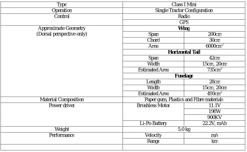
Table 1: Properties of CBSS Eagle UAV.
Type Class I Mini
Operation Single Tractor Configuration
Control Radio
GPS Approximate Geometry
(Dorsal perspective only)
Wing
Span 200cm
Chord 30cm
Area 6000cm2
Horizontal Tail
Span 42cm
Width 15cm, 20cm
Estimated Area 735cm2
Fuselage
Length 28cm
Width 15cm, 20cm
Estimated Area 490cm2
Material Composition Paper gum, Plastics and Fibre materials
Power driver Brushless Motor 11.1V
198W 900KV
Li-Po Battery 22.2V, mAh
Weight 5.0 kg
Performance Velocity m/s
Range km
II. SYSTEM MODEL AND ASSUMPTIONS
a. Alternating Energy Server: The Poly Voltaic (PV) System
Figure 1: PV Cell Equivalent Circuit [9, 10].
Output current, - - - - (1)
Where
Iph = photocurrent
T = junction temperature (20°C)
Is = reverse current of the diode (0.0002A)
V = voltage across the diode
Rs = series resistor of the cell (0.001Ω)
N = ideality factor of the diode Rsh = shunt resistor of the cell
q = electron charge = 1.602 * 10-19 C K = Boltzmann’s constant = 1.381*10-23 J/K
The photocurrent is a function of the solar irradiation level and the ambient temperature [4, 7]; which implies that the operational output of the PV cells changes with the variation in these parameters [4]. However, a typical PV cell generates a voltage around 0.5 to 0.8 volts [6] at 1 to 2 watts per cell. The work considers a PV cell design configuration that would be able to provide the required wattage values necessary to operate the vehicle.
b. Smart Power Supply (SPS) Algorithm
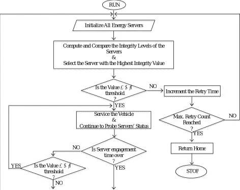
The algorithm was designed with the capability of probing the energy levels of the servers with respect to a certain threshold level before the vehicle could be activated. It requires that this threshold level should be set to a pre-determined value before launching the vehicle. It is important that this value would be sufficient enough for the execution of the ‘Return Home mode’ else the system would decline operation. The Return Home mode in this case could be the utilization of a reserved energy that would be sufficient to retract the flight path using the GPS coordinate system, fly the vehicle safely to a safe zone, land the vehicle safely without crashing, etc. The operation of the proposed SPS algorithm could be shown with the aid of a data flow diagram as shown in Figure 2.
The SPS integrated device is a device on which the SPS algorithm runs. The device is the control point that switches the service responsibility among the servers based on their energy integrity levels. The operation of the SPS algorithm is such that it compares the integrity of the servers and assigns the service responsibility to the server with the highest integrity value. If all the servers have equal values, the SPS will then assign the responsibility based on a predefined priority. The chosen server would assume the responsibility to service the operation of the vehicle. Other servers could use that period to upgrade their integrity values in order to stand a good chance to be the chosen server in the next comparison. Any chosen server would voluntarily make itself available for comparison again only when certain defined percentage of its original power value has been drained. It can resume the service responsibility if its current power value at that point is still greater than what could be obtained from the other servers otherwise another server would assume the duty.
The SPS would automatically switch the service responsibility to the next server with the highest integrity value once the value of the responsible server drops below the threshold value. This is called Coup D’etat operation of the servers. However, if none of the servers complied with the threshold condition at that point, the ‘Return Home mode’ would be activated automatically. The operational flowchart of the algorithm is as shown in Figure 3.
I
phI
DI
shR
shR
s+
Figure 2: Data flow diagram of an SPS integrated System.
Figure 3: Flowchart of Smart Power Supply (SPS) Algorithm Li-Po Battery
SPS Integrated
Device Return Home
PV Cells
Vehicle’s Operational Power
RUN
Initialize All Energy Servers
Compute and Compare the Integrity Levels of the Servers
&
Select the Server with the Highest Integrity Value
Is the Value ≥ Min.
threshold ?
NO
YES
Service the Vehicle &
Continue to Probe Servers’ Status
Is Server engagement time over
? Is the Value ≥ Min.
threshold ?
NO
YES YES
NO
NO Max. Retry Count
Reached ?
Return Home
c. Graphic User Interface
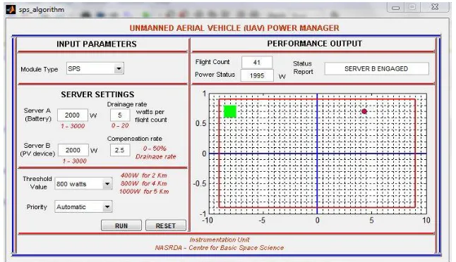
The UAV Power Manager was developed using MATLAB Graphic User Interface Development Environment (GUIDE) as shown in Figures 4 and 5. It is designed to work on two modes: The Conventional mode and the SPS integrated mode. In the Conventional mode, only one server (the Li Po energy source) is utilized for the operation. The SPS integrated mode has the intelligence to switch operation between the two available power sources based on the pre-designed conditions.
The Graphic User Interface (GUI) has two sections: The Input Parameter Section and The Performance Output Section. The Input Parameter Section allows the user to pre-set the input parameters, simulate it with the ‘RUN’ button and even reset the parameters to the default values with the ‘RESET’ button. The performance Output section shows the flight count, the status report, its power status and the flight animation of the vehicle. The flight count is a measure of hops/distances the vehicle covers before the energy sources run out. The graph represents the flight region and the circular plot on the graph represents the vehicle. The alternating green and red colours of the vehicle are indications that show respectively when either server A (Li Po Battery) or server B (PV device) is active.
Figure 4: MATLAB GUI Interface showing Flight Animation when Server A is Active.
III. RESULTS AND DISCUSSIONS
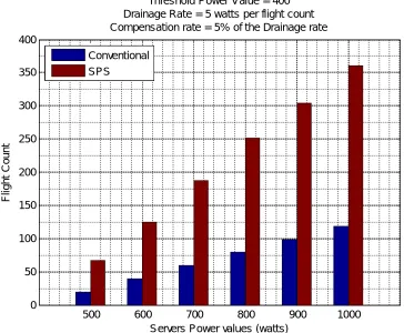
The performance results obtained is presented in Figure 6. It shows the plot of server power values against the flight counts. It also details the simulated conventional and the SPS operational modes for the vehicle. From the graph, it was observed that for every server power value, the SPS operation mode achieved more than hundred percentage (100%) flight count when compared with the conventional operation mode for a set threshold power value of 400watts, drainage rate of 5 watts per flight count and a compensation rate of five percentage (5%) of the drainage rate. It has been observed that the vehicle recorded more flight counts using the SPS operation mode than the conventional operation mode at different server power values. This improvement in terms of number of flight count is attributed to the ability of the system to compensate for some drained portion of the Li Po battery through the designed close loop system during the flight period. The graph can also be very useful in mission planning with regards to knowing the required flight counts and server power values needed to successfully plan and carry out any flight operation.
500 600 700 800 900 1000
0 50 100 150 200 250 300 350 400
Servers Power values (watts)
F
li
g
h
t
C
o
u
n
t
Threshold Power Value = 400 Drainage Rate = 5 watts per flight count Compensation rate = 5% of the Drainage rate
Conventional SPS
Figure 6: Performance Result for the Two Operational Modes of the UAV Power Manager.
IV. CONCLUSION
The work presented a novel way of extending the flight endurance of an Unmanned Aerial Vehicle using the SPS algorithm. The system has the intelligence to make optimal decision based on certain predefined parameters. Performance result from the work showed that the proposed SPS algorithm could guarantee more than hundred percentage (100%) power supply improvement to the UAV system, which can amount to extended flight endurance time, extended distance coverage for successful execution of any planed mission.
REFERENCES
[1] Austin Reg, “Introduction to Unmanned Aircraft Systems (UAS),” in Unmanned Aircraft Systems: UAVS Design, Development and
Deployment, 1st ed. Southern Gate, UK: John Wiley & Sons Ltd, pp. 1 – 15, 2010.
[2] Unmanned Aircraft Systems: Terminology, Definitions and Classification, Ministry of Defence, Wiltshire, 2010.
[3] How J.P. et al. “Increasing autonomy of UAVs.” Robotics & Automation Magazine, IEEE 16.2, pp. 43-51, 2009.
[4] Meyer, Johan, Francois Du Plessis, and Willem Clarke. Design considerations for long endurance unmanned aerial vehicles. INTECH
Open Access Publisher, 2009.
[5] Albaker, B. M. "Preliminary architectonic design for a smart solar-powered UAV." In Clean Energy and Technology (CEAT), 2013 IEEE
Conference on, pp. 238-242. IEEE, 2013.
[6] Sick, Friedrich, and Thomas Erge. Photovoltaics in buildings: a design handbook for architects and engineers. Earthscan, 1996.
[7] Harmon, Frederick G., Andrew A. Frank, and Jean-Jacques Chattot. "Conceptual design and simulation of a small hybrid-electric
unmanned aerial vehicle." Journal of aircraft 43, no. 5 (2006): 1490-1498.
[8] Hung, J. Y., and Luis Felipe Gonzalez. "On parallel hybrid-electric propulsion system for unmanned aerial vehicles." Progress in
Aerospace Sciences 51 (2012): 1-17
[9] T. Salmi, M. Bouzguenda, A. Gastli and A. Masmoudi, “MATLAB/Simulink Based Modeling of Solar Photovoltaic Cell,” International Journal of Renewable Energy Research, Vol. 2, No. 2, 2012.
[10] H. Beilla, R. Youcef and M. Fatima, “A Detail Model of Photovoltaic Module using MATLAB,” NRAIG Journal of Astronomy and Geophysics, Vol. 3, pp. 53 – 61, 2014.
[11] Ravi, Ashwin. "UAV Power Plant Performance Evaluation." Oklahoma State University (2010): 1-41.
[12] Albaker, B. M., and Asmaa H. Rasheed. "Mathematical modelling and realization of flight trajectories for an intelligent fixed-wing solar-powered UAV." In Clean Energy and Technology (CEAT) 2014, 3rd IET International Conference on, pp. 1-6. IET, 2014.
[13] Illeez, Mustafa. "Capabilities of Unmanned Aircraft Systems in Hybrid Wars."International Journal of Unmanned Systems Engineering. 2, no. 4 (2014): 46.
[14] Wang, Fei, Jinqiang Cui, Ben M. Chen, and Tong H. Lee. "Flight Dynamics Modeling of Coaxial Rotorcraft UAVs." In Handbook of