ISSN (Print) : 2320 – 3765 ISSN (Online): 2278 – 8875
I
nternational
J
ournal of
A
dvanced
R
esearch in
E
lectrical,
E
lectronics and
I
nstrumentation
E
ngineering
(An ISO 3297: 2007 Certified Organization)
Vol. 4, Issue 5, May 2015
Hand Gesture Recognition Based Robot Using
Accelerometer Sensor
Archika Setia
1, Surbhi Mittal
2,Padmini Nigam
3,Shalini Singh
4, Surendra Gangwar
5UG Student, Department of ECE,Shri Ram Murti smarak Women’s College of Engg. & Technology, Bareilly,
India1,2,3,4
Ass. Prof. , SRMS Women’s College of Engg. & Technology,Bareilly (U.P.), India 5
ABSTRACT: In today’s era human-machine interaction is becoming widespread. So, with the introduction of new technologies the gap between machines and humans is being reduced to ease the standard of living. Gestures have played a crucial role in diminishing this gap. This paper deals with design and implementation of an accelerometer-based hand gesture controlled robot controlled wirelessly using a small low cost, 3-axis accelerometer. A novel algorithm for gesture identification has been developed to replace the approach of conventional controlling mechanism of robots via buttons etc. by an innovative hand gesture based controlling. Using a microcontroller system the program has been written & executed [1].
KEYWORDS- Accelerometer, Arduino, Gesture, Microcontroller, Robotics.
I. INTRODUCTION
The current emerging technology in the field of science is Robotics. It is the new emerging booming field of great use to people in the coming years. These days a number of wireless robots are being developed and put to various applications and uses. In order to enhance the contribution of robot in our daily lives we need to find an effective way of communicating with robots. For this purpose, there have been certain developments in area of human-machine interaction. One common form of communication is Gestures that are not only limited to face, body and fingers but also hand gestures. In order to increase the use of robot in places where conditions are not certain like rescue operations, robots can be made to follow the instructions of human operator and perform the task accordingly. This proposes an integrated approach of tracking and recognition of hands which is intended to be used as human-robot interaction interface.
ISSN (Print) : 2320 – 3765 ISSN (Online): 2278 – 8875
I
nternational
J
ournal of
A
dvanced
R
esearch in
E
lectrical,
E
lectronics and
I
nstrumentation
E
ngineering
(An ISO 3297: 2007 Certified Organization)
Vol. 4, Issue 5, May 2015
Fig. 1: Hand Movements
As shown in Fig.1, various hand movements performed are: FORWARD, BACKWARD, LEFT and RIGHT. The standard input methods do not provide a natural instinctive interaction between humans & robot making it essential to create models for understandable communication between humans & robots.
II. LITERATURE SURVEY
Using Teach box for Programming and control of a robot is a tiresome and time-consuming task that requires technical knowledge. Therefore, the approach is to have new and more intuitive ways for programming & control of robot. In the robotics field, several research efforts have been made to create user-friendly teach pendants, implementing user interfaces such as color touch screens, a 3D joystick. But, these techniques are not efficient to control the robot as they do not give accurate results and provide slow response time. In the past years the manufacturers of robot have made efforts for creating “Human Machine Interfacing Device”[3].Using gesture recognition concept, it is possible to move a robot accordingly. Accelerometers are the main technologies used for human machine interaction which offer very reasonable motion sensitivity in different applications. Motion technology makes easy for humans to interact with machines naturally without any interventions caused by the drawbacks of mechanical devices. Accelerometer-based gesture recognition has become increasingly popular over the last decade compared to vision based technique. The factors that make it an effective tool to detect and recognize the human gestures are its low-moderate cost & relative small size of the accelerometers.
III. HARDWARE REQUIREMTNS
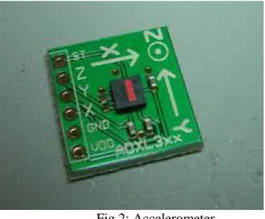
a. Accelerometer Sensor
The ADXL335 is a small, thin, low power 3-axis accelerometer which measures acceleration with a minimum full-scale range of ±3g along with measurement of the static acceleration of gravity in tilt-sensing applications, as well as dynamic acceleration resulting from motion, shock, or vibration. Tilting an accelerometer along its measured axis, gives the gravitational force relative to the amount of tilt.
ISSN (Print) : 2320 – 3765 ISSN (Online): 2278 – 8875
I
nternational
J
ournal of
A
dvanced
R
esearch in
E
lectrical,
E
lectronics and
I
nstrumentation
E
ngineering
(An ISO 3297: 2007 Certified Organization)
Vol. 4, Issue 5, May 2015
As shown in Fig.2, there are three axes that can be measured by accelerometer and labeled as X, Y and Z with each axis representing separate degree of freedom (DOF) and the data at that corresponding axis is turned into analog form. They are used in Mobile devices, Gaming systems, Disk drive protection, Image stabilization, Sports and health devices applications.
b. RF Module
RF stands for Radio Frequency. This module consists of further two parts: Transmitter (Tx) and Receiver (Rx). It is a small electronic device used to transmit and receive signal between two devices. It is available in different operating frequencies with different operating range. An Encoder Circuit & a Decoder Circuit is used along with the Transmitter & Receiver respectively in order to transmit & receive the message/signal. As shown in Fig.3 below, the RF Module operates at the frequency of 315MHz with an operating range of 400-500 meters.
RF transmission is better than IR because signals through RF can travel through larger distances while IR mostly operates in line-of-sight mode and also RF signals can travel even when there is an obstruction between transmitter & receiver. Moreover, RF transmission is more strong and reliable than IR transmission [4].
Fig.3: RF Module c. Microcontroller
ATmega16 microcontroller is used as the hardware platform. It is the controlling unit, to which all other components (Accelerometers, Motors, RF modules etc.) are interfaced. It is a low voltage, high performance CMOS 16-bit Microcomputer with 2K bytes of Flash Programmable & Erasable Read-Only Memory. It is an 8-bit high performance microcontroller of AVR family with low power consumption and is based on enhanced RISC) architecture with 131 powerful instructions. Most of the instructions execute in one machine cycle. It can work on a maximum frequency of 16MHz. It has 16 KB programmable flash memory, static RAM of 1 KB and EEPROM of 512 Bytes. It is a 40 pin microcontroller and have 32 I/O (input/output) lines.The device supports throughput of 16 MIPS at 16 MHz and operates between 4.5-5.5 volts.
d. Motor Driver
The primary need is to supply current to the motors as it cannot be done through the microprocessors. The L293D is a 16-pin IC dedicated to controlling of motor. It consists of two H-bridge which is a simplest circuit for controlling low current rated motor. H-bridge has four switches rotating motor in clockwise or anti-clockwise direction.
IV. SOFTWARE REQUIREMENT
For software implementation we are deploying two software packages namely -WIN AVR STUDIO 4.0 and PROTEUS.
e. WINAVR STUDIO 4.0
ISSN (Print) : 2320 – 3765 ISSN (Online): 2278 – 8875
I
nternational
J
ournal of
A
dvanced
R
esearch in
E
lectrical,
E
lectronics and
I
nstrumentation
E
ngineering
(An ISO 3297: 2007 Certified Organization)
Vol. 4, Issue 5, May 2015
pipeline design i.e. the next machine instruction is fetched as the current one is executing. Most instructions take just one or two clock cycles, making AVRs relatively fast among 8 bit microcontrollers.
f. PROTEUS
It is a fully functional and procedural programming language created in 1998 by Simone Canella which incorporates many functions derived from other languages: C, BASIC, Assembly, Clipper/dBase. The main usage of this language is transforming data from one form to another. It was designed to be practical, readable and consistent.Its major points are powerful manipulation; comprehensibility of Proteus scripts; availability of advanced data structures: arrays, queues (single or double), stacks, bit maps, sets, AVL trees. It has a fully functional, procedural approach and variables are untyped, do not need to be declared, can be local or public and can be passed by value or by reference. New functions can be defined and used as native functions. There are three Data types that are supported by Proteus: integer numbers, floating point numbers and strings. It includes hundreds of functions for accessing file system; sorting data; manipulating data and strings; interacting with the user (console functions) calculating logical and mathematical expressions.
V. BLOCK DIAGRAM
As shown in Fig.4, the analog data at the corresponding axis from the accelerometer is applied as an input to the microcontroller where it is processed resulting in an 8-bit data.
Fig.4 : Block Diagram of Transmitting Section
This data is then encoded into 4-bit data and then transmitted through RF module via an antenna. The accelerometer and microcontroller are controlled through a power supply. A digital LED is connected to one pin of microcontroller to indicate the presence of data at the corresponding pin.
ISSN (Print) : 2320 – 3765 ISSN (Online): 2278 – 8875
I
nternational
J
ournal of
A
dvanced
R
esearch in
E
lectrical,
E
lectronics and
I
nstrumentation
E
ngineering
(An ISO 3297: 2007 Certified Organization)
Vol. 4, Issue 5, May 2015
Fig.5 : Block diagram of Receiving Section
The motor rotates in clockwise or anti-clockwise direction depending on the terminals of motor connected to motor driver IC.
VI. RESULTS DISCUSSION AND ANALYSIS
As shown in Fig.6, this is the PCB Layout of the transmitter section. It incorporates various components like Accelerometer, Microcontroller, encoder, single-pole antenna, RF module and various mini-components like capacitor, LED’s and voltage regulator
Fig.6: PCB Layout of Transmitter Section
ISSN (Print) : 2320 – 3765 ISSN (Online): 2278 – 8875
I
nternational
J
ournal of
A
dvanced
R
esearch in
E
lectrical,
E
lectronics and
I
nstrumentation
E
ngineering
(An ISO 3297: 2007 Certified Organization)
Vol. 4, Issue 5, May 2015
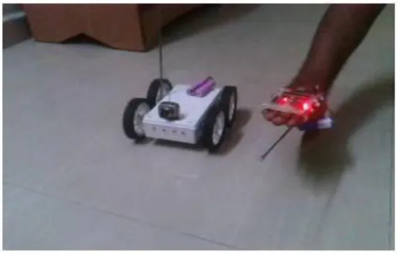
Fig.7: Top view of Robot
As shown in Fig.7, the user makes the hand movements and the robot moves accordingly in desired direction. The Table no.1 shows the comparative analysis of various technologies and shows that the accelerometer based recognition undermines the effect of other technologies.
Table no.1 Comparative Analysis
VISION- BASED GESTURE RECOGNITION
FINGER GESTURE RECOGNITION
ACCELEROMETER BASED GESTURE RECOGNITION
It basically worked in the field of Service Robotics & the researchers finally designed a Robot performing the required task. They designed a gesture-based interface to control a robot equipped with a manipulator.
The aim is to make it feasible to interact with a portable device or a computer through the recognition of finger gestures
It has become increasingly popular. The low moderate cost & relative small size are the two factors that make it an effective tool to detect and recognize human body gestures.
The vision based gesture recognition system designed a robot which performs the task of cleaning through interfacing between robot and manipulator[5].The Finger gesture recognition make use of fingers to interact with computer. The Accelrometer based hand gesture recognition makes use of accelerometer as a tool to detect and recognise human gestures.
VII. CONCLUSIONANDFUTUREWORK
ISSN (Print) : 2320 – 3765 ISSN (Online): 2278 – 8875
I
nternational
J
ournal of
A
dvanced
R
esearch in
E
lectrical,
E
lectronics and
I
nstrumentation
E
ngineering
(An ISO 3297: 2007 Certified Organization)
Vol. 4, Issue 5, May 2015
to communicate with the robot. The 3- axis accelerometer selected to be the input device of this system captures the human gestures. When compared with the other input devices accelerometer is easier to work and offers the possibility to control a robot by wireless means. The low price and short set-up time are other advantages of the system but an important limitation to consider is the reliability of the system [6]. Physical hardship to the user is avoided through the use of accelerometer as with the twist of the hand, the user gets the ability and freedom to turn the robot into the desired direction.
Future work will build upon the improvement of the correctly recognized the gestures. One approach might be the implementation of a gyroscope into the system, in order to separate the acceleration due to gravity from the inertial acceleration and second approach can be that we can install a GPS in the system to track the position of robot. The use of more accelerometers attached to the arms is another possibility.
REFERENCES
[1] International Journal of Advanced Technology in Engineering and Science Volume No.02, IssueNo.05, May2014
[2] http://research.ijcaonline.org/volume79/number13/pxc3891906.pdf
[3] http://ijsetr.org/wp-content/uploads/2013/07/IJSETR-VOL-2-ISSUE-3-749-755.pdf
[4] http://researchtrend.net/ijet41/3%20DIKSHA%20NGF.pdf
[5] International Journal of Computer Applications (0975 – 8887) Volume 79 – No 13, October 2013