a
Sylwia Hoejowska1,a, Tomasz Musia2 and Magdalena Piasecka2
!""#$%!&'"
$ ( !""#$%!&'"
The aim of this paper was to present the concept of mathematical models of heat transfer in flow boiling in an annular mini gap between the metal pipe with enhanced exterior surface and the external glass pipe. The one- and two-dimensional mathematical models were proposed to describe stationary heat transfer in the gap. A set of experimental data governed both the form of energy equations in cylindrical coordinates and the boundary conditions. The models were formulated to minimize the number of experimentally determined constants. Known temperature distributions in the enhanced surface and in the fluid helped to determine, from the Robin condition, the local heat transfer coefficients at the enhanced surface fluid contact. The Trefftz method was used to find two-dimensional temperature distributions for the thermal conductive filler layer, enhanced surface and flowing fluid. The method of temperature calculation depended on whether the area of single-phase convection ended with boiling incipience in the gap or the two-phase flow region prevailed, with either fully developed bubbly flow or bubbly-slug flow. In the two phase flow, the fluid temperature was calculated by Trefftz method. Trefftz functions for the Laplace equation and for the energy equation were used in the calculations.
In recent years, many experimental and theoretical works have been published to address the issues of heat transfer in flow boiling in mini- and microchannels. The use of minichannels in heat exchangers improves the effectiveness of heat transfer processes, which is the major advantage of this technology. An example of experimental studies conducted to investigate practical applications for heat exchangers with minichannels can be found in [1], where the use of mini-gaps in microchip cooling is discussed. In [2], the authors report heat transfer investigations of the initial flow boiling phases in mini-gaps for the ecological refrigerants which are superseding traditional thermodynamic agents due to strengthened requirements. In [3], the researchers present the studies and models for the boiling of refrigerant in the heat exchanger and determine the heat transfer coefficient for the channels with conventional and small diameters. In [4], boiling heat transfer for the counter-flow of R134a was studied. Experimental investigations [5] show that the heat transfer coefficient in compact heat exchangers with mini gaps is higher. Investigations often deals with frictional pressure drop in minichannels [6].
The use of microstructured heated surfaces in boiling research is known to intensify the heat transfer process. Enhanced surfaces are considered to be very efficient because of providing a large number of nucleation sites. The properties of a microstructured surface can be modified using chemical, thermal, mechanical or combined mechanical and thermal processes. The thermal
processes include plasma spraying, electric arc spraying, sintering, laser surface texturing or electrical discharge texturing [7-13]. Very broad critical review of past achievements can be found in [14], where much room was devoted to discussing mathematical models and their application to numerical analysis. The most general model, i.e. the two fluid four-field model, which at least theoretically allows permanent modelling of flow structure changes is presented in [15]. Used mainly in numerical analysis to adiabatic/non-adiabatic, steady/ unsteady flows through the channels with different cross-sections and hydraulic diameters, the model gave satisfactory results [16, 17]. A major problem in solving this type of equations is to determine the appropriate set of closure equations. Solving such a complex system of equations, even when using CFD commercial software is not always possible, especially in the case of inverse problems.
In the present paper, one- and two-dimensional mathematical models are proposed to describe the stationary heat transfer in flow boiling of cooling liquid in the cylindrical annular gap. A set of experimental data governs the form of energy equations in the cylindrical coordinates and the boundary conditions. The two- dimensional model is formulated to minimize the number of experimentally determined constants. In addition to the fixed thermal-flow parameters, this model uses two quantities determined experimentally: the surface temperature of the thermal conductive filler layer and void fraction. The method for determining the fluid temperature distribution depends on the flow type. The C
temperature of the fluid is calculated in one way when the domain of single-phase convection ended with the boiling incipience prevails in the gap and in a different way, when the domain with two-phase flow dominates along with developed bubbly or bubbly-slug flow. In the two-phase flow, the calculation of fluid temperature is related to the approximate determination of temperature distributions in the main elements of the measurement module. Paper [18] proposes Trefftz method to determine two-dimensional temperature distributions in the thermal conductive filler layer, in the layer with enhanced surface and in the fluid. The knowledge of temperature distributions in the heating surface and fluid helps to determine, using the Robin condition [19], the local heat transfer coefficients at the interface of the thermal conductive filler and the fluid.
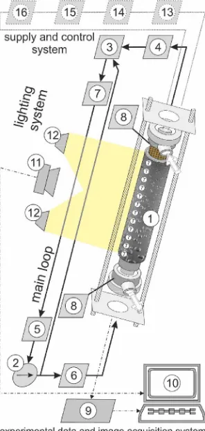
The experimental setup (figure 1) consists of several systems: the test loop in which FC-72 Fluorinert circulates as the working fluid, the data and image acquisition system, the supply and control system, and the lighting system.
The schematic diagram of the main loops at the experimental setup, 1-measurement module with a mini annular gap; 2-rotary pump; 3-compensating tank/pressure regulator; 4-tube-type heat exchanger, 5-filter, 6-rotameters/flowmeter; 7-deaerator, 8-pressure transducer, 9-data acquisition station, 10- computer, 11-digital SLR camera, 12-halogen reflectors, 13-inverter welder, 14-voltmeter, 15-ammeter, 16-shunt.
The test loop is composed of a rotary pump, a heat exchanger, a compensating tank, rotameters, a filter, and a deaerator. The data and image acquisition system consists of two digital cameras, an infrared camera, a data acquisition station, a computer with special software, and the lighting. The experimental setup is similar to that described in [19-22].
Figure 2 presents the testing module with an annular mini gap. The mini gap 1-3 mm wide will be created between the metal pipe (2) with enhanced exterior surface and the external tempered glass pipe (1) positioned along the same axis.
The measurement module layout with annular mini gap: 1-glass pipe for viewing flow patterns, 2-metal pipe with enhanced surface, 3-annular mini gap, 4-cartridge heater, 5-module header with sealing, 6-inlet port for the medium, 7-outlet port for the medium, 8-thermoelements between the heater (4) and the metal pipe (2) in the thermal conductive filler layer, 9-stirrup bolts.
thermoelement sensors with a spacing of approximately 1 cm in the flow line. Thermoelement wires will run in the gap between the heater and the metal pipe in the thermal conductive filler layer. The module header will have a sealing (5) and the sensors of successive thermoelements and pressure transducers to measure the coolant temperature and positive pressure in the inlet/outlet to/from the annular mini-gap.
The assumptions made in the mathematical model (see figure 3) included the steady state in the measurement module and the laminar flow of the fluid (Reynolds number < 2 100). Two dimensions were provided for in the proposed approaches: dimension parallel to the flow direction and dimension perpendicular to for the widths of the consecutive elements of the measurement module. The temperature distribution for the elements in the module is only dependent on variables and , (it is axi-symmetric). The temperature distribution of the coolant in the model is dependent on the flow type. Different techniques are used to calculate the temperature in the case when the single-phase convection region prevails in the annular gap, ended with boiling incipience, and in the case of two-phase flow with developed bubbly or bubbly-slug boiling. The first case mentioned above is further in the text referred to as single phase flow with boiling incipience, the latter case simply two-phase flow. In both cases, the assumptions were as follows: - the fluid flow in the minichannel is laminar and stationary, with a steady mass flux,
- fluid velocity has only one nonzero component () parallel to the heating surface, which satisfies the condition arising from the momentum equation:
1
(1)
where is the pressure, is the dynamic viscosity of the fluid and is the length of the minichannel, and - the fluid temperature at the inlet () and outlet () of the minichannel is known.
Placing the thermoelement sensors on the external surface of the thermal conductive filler layer, figure 3, gives the surface temperature at points: 1, 2, ..., .
Two approaches are proposed below for describing heat transfer in particular elements of the measurement module with the annular mini-gap.
!
In the one-dimensional heat transfer model, for each cross-section ( = ), the heater temperature is
assumed to satisfy the Poisson equation in the form
1
(2)
where - is the volumetric heat flux generated in the heater, and - is the heat transfer conductivity of the heater.
Diagram illustrating the assumptions adopted for the calculation methods (pictorial view, not to scale).
Equation (2) was solved assuming that:
- the temperature of the heater at each point of the cylinder is finite (including inside, where =0).
- for = 1 at each point 1, 2, ..., , the condition below
is satisfied
1 1 1
2
1 (3)
Taking for =1 equal temperatures of the heater,,
and the thermal conductive filler and considering that
the width of the measurement module elements is small, we can write
1 2
1 1
(4)
where 2 are the temperatures measured using the thermocouples at points 2 , figure2.
Calculating temperature 1 from (3) and (4), the solution to equation (2) can be expressed as
2
4
1 1 2 2 1 2
(5)
Assuming equal respective temperatures and heat fluxes at the boundaries = 2 and = 3, figure 3, at each
measurement point 1, 2, ..., , we have
2 2 3 2 1 3
2
3 2 1 3 2 (7)
From (7) and from the Robin boundary condition, [23], we obtain the formula for the local heat transfer coefficients at points 1, 2, ..., , at the interface between the enhanced surface and the fluid
2 2 3 2 1 3 2 1 22 (8)
In formula (8), the reference temperature is calculated depending on the flow type:
- for single phase flow with boiling incipience, the fluid temperature changes linearly in the minichannel, from the inlet temperature () to the outlet temperature(). Both temperatures are known from the measurements;
- for two-phase flow in this approach, we assume that
ifif (9)
!
In the two-dimensional approach we assume that the temperature of the thermal conductive filler layer and of that of the enhanced surface both satisfy respective equations
a) 0 b) 0 (10)
where the Laplace operator in coordinates (, ) is defined
by 2
2 1
. The following boundary
conditions, figure 3, were adopted for the temperature
2 1
for = 1 (11)
2 (12
)
0
for a) = 0 and b) = (13)
Analogous assumptions were adopted for the temperature of the thermal conductive filler layer, , i.e.,
2 2 1 2
for = 2 (14)
2 and b) 2 2 (15
)
0
for a) = 0 and b) = (16)
For two-phase flow, the fluid temperature is assumed to satisfy the energy equation in the form
(17)
where the fluid velocity in the mini-gap () is calculated from condition (1), and are the specific heat and
liquid density, respectively. The following boundary conditions were adopted for equation (17)
a) 0 , b) (18)
1 for = (19)
where is the experimentally determined void fraction. Also, on the boundary = , the fluid temperature is assumed to satisfy condition (9).
Known temperature distributions of the enhanced surface, (,), and the fluid, (,), allows determining the heat transfer coefficient as in 3.1, from the Robin condition, which in this approach has the following form
3 3 (20)
The reference temperature is calculated depending in the flow type in the same way as in 3.1 for single phase flow with boiling incipience, and as an average liquid temperature in the gap for two-phase flow, i.e.,
4 3 3 4 1 (21)In the two-dimensional model, the form of energy equations and that of the boundary conditions depend on the set of the experimental data. The model was formulated in the way which minimizes the occurrence of experimentally determined constants in this case, these are temperature measurements of the filler layer surface and void fraction. For single phase flow with boiling incipience, the solution of the differential equations leads to the solution of one direct heat transfer problem in the filler layer and one inverse problem in the enhanced layer. For two-phase flow, the procedure of calculating fluid temperature is coupled with the process of determining temperature distributions in two elements of the measurement module, which leads to a triple coupled heat transfer problem. This problem is composed of one direct problem (filler layer) and two successive inverse problems (filler layer and fluid).
&$)
transfer problems. The Trefftz method, as confirmed by available research reports, [19,24], ensures stable results also for inverse problems. The essence of the Trefftz method lies in approximating an unknown solution of a differential equation using a linear combination of Trefftz functions, that is, the functions which satisfy the equation exactly. Two types of Trefftz functions were used in the numerical calculations: Trefftz functions for the Laplace equation (10) and Trefftz functions for energy equation (17). The Trefftz functions for equation (10) are defined by the following formula [25]
2 0 2 2 2 2 0 2 2 1 (22)
where [] denotes the greatest integer function.
Trefftz functions for the energy equation (17) are the sum of functions 0 and polynomials dependent on the form of the velocity profile . This relationship can be expressed as
10 (23)
Assuming that
, functions ,
!!!
12 , satisfy the relationship
1 1 1 (24)
The inverse operator 1
for monomial in the form
is defined for = 0, 1, 2..., as follows
2 for 2 1 2 1 0 for 2 2 2 1 2 2 2 2 2 1 (25)Formula (25) applies when velocity is a polynomial. If is not a polynomial, the function is expanded as a Taylor series, which allows representing it in the form of a polynomial, to a random accuracy. The Trefftz functions given by formulas (22) and (23) will be used to determine approximate solutions to equations (10) and (17), respectively.
For example, the solution of equation (17) is approximated by the linear combination of the Trefftz functions
" 1 (26)where " means the number of Trefftz functions (23). The unknown coefficients of linear combination (26) are determined by minimizing the functional that describes
the mean squared error with which function (26) satisfies conditions (9), (18) and (19). In this case, the minimized functional has the following form
" " " " # 0 2 0 3 0 2 0 3 3 2 0 2 1 1 0 4 3 4 3 (27)
The minimum of the functional is determined by solving the linear equation system, where coefficients
of linear combination are the unknown quantities
0 #
for = 1, 2,, " (28)
The temperatures of the filler layer, , and the enhanced layer, , are determined analogously using the Trefftz functions (22). The approximate temperature distribution in the thermal conductive filler layer, , is calculated before calculating the temperature of the external enhanced surface, , and that of the fluid, . The Trefftz method- based approximate temperatures , and (two-phase flow) are continuous functions, which satisfy equations (10a), (10b) and (17) exactly, with the adopted boundary conditions satisfied approximately.
"#
The purpose of the paper was restricted only to presenting:
- the conceptions of two mathematical models which describe the heat transfer in flow boiling in annular gaps, - the procedure for calculating the heat transfer coefficient at the interface between the enhanced surface and the fluid.
Further studies will focus on comparison of the results obtained from both proposed mathematical models and their verification by comparison to the existing theoretical models. The other task will be determining the thermal stress that occurs on the surfaces of a heat exchanger. Thermal strains have a significant influence on heat transfer conditions because in the case of the minichannel surface dimensions, this may lead to local narrowing in the mini-gaps, thus changing the physical conditions of heat exchanger operation. In extreme cases, thermal strains may cause a complete geometric deformation of the mini-gap.
$%
The research has been financially supported by the National Scientific Center from funds granted by virtue of decision No. DEC-2013/09/B/ST8/02825.
&
1. L. A. Campbell S. G. Kandlikar, $!% &!'!
( (, USA (2004)
2. T. Bohdal, Annual Set Env. Protect. (in Polish) , 262279 (2000)
3. D. Mikielewicz, J. Mikielewicz, J. Tesmar, Int. J. Heat Mass Tran. , 39493956 (2007)
4. J. Kaew-On, K. Sakamatapan, S. Wongwises, Exp. Therm. Fluid Sci. , 364374 (2011)
5. T. Bohdal, Annual Set Env. Protect. , 107126 (2013)
6. K. Dutkowski, Heat Tran. Eng. , 321330 (2010) 7. B. Grabas, Arch. Metall. Mater. (1), 3339 (2015) 8. B. Grabas, Exp. Therm. Fluid Sci. , 499508
(2015)
9. B. Grabas, Adv. Mater. Research , 7175 (2014)
10. W. Depczyski, $! % &! '! (()
(*+%,-., Poland (2014)
11. W. Depczyski, S. Spado, P. Mynarczyk, E. Ziach,
$! %. &! '! (! ! *+ %,-/
Poland (2015)
12. N. Radek, E. Wajs, M. Luchka, Powder Metallurgy Metal Ceramics (3-4), 197201 (2008)
13. N. Radek, B. Antoszewski, Kovove Materialy-Metallic Mater. (1), 3138 (2009)
14. Z. Guo, D.F. Fletcher, B.S. Haynes, J. Comp. Multiph. Flows , 79110 (2014)
15. R.T. Lahey Jr., $! 0&&& 12 "! '! +(
,USA (1998)
16. M.Z. Podowski, Int. J. Numer. Methods Heat & Fluid Flow , 491513 (2008)
17. M.Z. Podowski, R.M. Podowski, Sc. Techn. Nucl. Instal., 1-10; doi: 10.1155/2009/387020 (2009)
18. T. Trefftz, $!% &!'!+!!, 131-137
(1926)
19. S. Hoejowska, M. Piasecka, Heat Mass Tran. , 10531063 (2014)
20. M. Piasecka, Heat Tran. Eng. , 903912 (2014) 21. M. Piasecka, Ann. Nucl. Energy, 282293 (2014) 22. M. Piasecka, Adv. Mater. Research , 95100
(2014)
23. S. Hoejowska, M. Piasecka, E. Poniewski, Int. J. Therm. Sci. , 10491059 (2009)
24. S. Hoejowska, R. Kaniowski, M.E. Poniewski, Int. J. Numer. Methods & Heat Fluid Flow 811824 (2014)
25. M.J. Ciakowski, S. Hoejowska, L. Hoejowski,