Simulation of the optical performance of the
Fluorescence detector Array of Single-pixel
Telescopes
Miroslav Pech1,*, Justin Albury2, Jose A. Bellido2, John Farmer3, Toshihiro Fujii4, Petr Hamal5, Pavel Horvath5, Miroslav Hrabovsky5, Ladislav Chytka5, Max Malacari3, Dusan Mandat1, John N. Matthews6, Xiaochen Ni3, Libor Nozka1, Miroslav Palatka1, Paolo Privitera3, Petr Schovanek1, Stan B. Thomas6 and Petr Travnicek1 (FAST Collaboration) https://www.fast-project.org
1 Institute of Physics of the Academy of Sciences of the Czech Republic 2 Department of Physics, University of Adelaide
3 Kavli Institute for Cosmological Physics, University of Chicago
4 Institute for Cosmic Ray Research, University of Tokyo, Kashiwa, Chiba, Japan 5 Palacky University, RCPTM
6 High Energy Astrophysics Institute and Department of Physics and Astronomy, University of Utah
Abstract. The Fluorescence detector Array of Single-pixel Telescopes (FAST) is a proposed large-area, next-generation experiment for the detection of ultra-high energy cosmic rays via the atmospheric fluorescence technique. The telescope’s large field-of-view (30°x30°) is imaged by four 200 mm photomultiplier-tubes at the focal plane of a segmented spherical mirror of 1.6 m diameter. Two prototypes are installed and taking data at the Black Rock Mesa site of the Telescope Array experiment in central Utah, USA. We present the process used for optimization of the optical performance of this compact and low-cost telescope, which is based on a simulation of the telescope’s optical point spread function.
1 Introduction
The origin of the ultra-high energy cosmic rays (UHECRs) is a hot topic in astrophysics. Some of these particles (protons, nuclei, electrons or neutrinos) have energies exceeding 1020 eV (~16 J) [1]. As Kenneth Greisen, Georgi Zatsepin, and Vadim Kuzmin pointed out [2,3], extremely high energy particles interact with relic photons of the cosmic microwave background, leading to their relatively short mean interaction lengths.
lower energy cosmic rays, extra high energy cosmic rays can potentially be used for point source astronomy.
Measurements of the mass composition of cosmic rays, their energy spectrum, and their arrival directions are severely limited by their flux. Extremely large ground areas must therefore be instrumented in order to collect enough statistics to advance the field, and the next generation of detectors will require an aperture which is larger by an order of magnitude relative to the current generation experiments. This large area is essential, because the flux of particles with energies exceeding 1020 eV is lower than 1 particle/km2/century.
The Pierre Auger Observatory (Auger) [4] and the Telescope Array Experiment (TA) [5] are the largest UHECR experiments currently in operation, and combine two well-established techniques to measure air showers produced upon the interaction of
cosmic rays with the Earth’s atmosphere.
In each experiment an array of surface detectors measures the lateral distribution of shower particles at the ground level, while telescopes on the
array’s periphery measure the longitudinal development of the air shower through the emission of faint, isotropic fluorescence light.
Auger covers an area of over 3000 km2 close to the town of Malargüe in the province of Mendoza, Argentina. TA is located near the town of Delta in central Utah, USA, and covers an area of 700 km2.
The next generation of experiments will require an aperture which is larger by an order of magnitude. This may be accomplished by fluorescence detection of UHECRs with a giant ground array. Low-cost, easily-deployable detectors will be essential for a future based experiment. We present a ground-based fluorescence detector (FD) telescope concept which would fulfil these requirements. The Fluorescence detector Array of Single-pixel
Telescopes (FAST) [6] would consist of compact FD telescopes featuring a smaller light-collecting area and far fewer pixels than current-generation FD designs, leading to a significant reduction in cost. FAST stations, powered by solar panels and with wireless connection, could be deployed in an array configuration to cover a very large area at low cost.
In this paper we presentour approach to the design of this kind of fluorescence telescope taking into account current technological capabilities and optical simulations. Three prototype telescopes using this design are installed and fully functional at the Black Rock Mesa site of the Telescope Array experiment.
2 FAST optical design
The telescope design [7] (figure 1) consists of a segmented spherical glass mirror of 1.6 m diameter (produced by Laboratory of Optics in Olomouc, Czech Republic) and a UV band-pass filter (ZWB3, Shijiazhuang Zeyuan Optics) with a 1 m2 aperture.
Four 200 mm PMTs (mod. R5912-03, Hamamatsu) and active bases (mod. E7694-01, Hamamatsu) are installed at the focal plane of the segmented mirror in a 2x2 matrix, covering a 30°x30° field of view. The telescope frame is covered with a shroud to shield the optical system from dust and stray light.
Detailed technical parameters of the FAST optical system:
• Segmented mirror
• 1.6 m mirror diameter
• 2.39 m2 mirror reflecting area
• effective collecting area of 1 m2 including the camera and structure shadow
• 9 mirror segments
• Polished borosilicate substrate
• Al-SiO2 reflective coating
• Radius of curvature 1380 mm
• Telescope field of view (FOV) 30°x30° • Camera - mirror distance 690/710 mm (FAST1/2)
• Camera side mirrors, covering dead zones on the camera edge
• Camera mirror pyramids, covering dead zones at the camera centre
• Diffuser on the camera dead space
Fig. 1. Picture of the FAST telescope, FAST CAD model of the whole telescope and details of the camera composition from ray tracing software.
3 Optical design
Design of the FAST optics was based on several considerations (figure 2):
1) Field of view of the system
The field of view was chosen to be the same as current-generation fluorescence telescopes installed at Auger and TA. 2) Camera dimensions and angular
resolution
In order to minimize the price of the system, four Hamamatsu 8 inch PMTs were selected to cover the camera’s front surface of 500 x 500 mm. The PMTs’
size allows for coverage of the entire detection plane with minimal dead space.
These dead spaces are minimized with additional optical elements.
3) The required collecting area In order to achieve sufficient sensitivity, a 1 m2 collection area was chosen. 4) Optical workshop production
possibilities
The optical workshop of the optical producer has several limitations in the production of large optical components. The maximal circumscribed circle of the mirror facet must be smaller than 650 mm. The workshop is also limited in its capability to produce mirrors with certain radii of curvature.
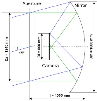
Fig. 2. The dimensions of the FAST prototype optical system. Da is the
face-to-face size of the octagonal telescope aperture, Di is the side length of the square camera box,
Dm is the diameter of the primary mirror, and
l is the mirror-aperture distance.
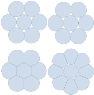
Several mirror designs were assessed during development of this system (figure 3). The final and optimal solution uses one central circular mirror
surrounded by 8 “petals” (right picture
Fig. 3. Possible FAST mirror segmentation.
4 FAST
optical
system
simulation
Ray-tracing simulations of the optical system were done using Zemax OpticStudio 14. This commercially-available software allows for a simulation of the entire optical and mechanical design of the FAST telescope. The input for the analysis was obtained by scripting the analysis process in the Matlab development software. The Matlab software was used for the analysis and visualization of the simulation results. The simulation model includes a mirror with a realistic surface shape and spectral reflectance, the complete mechanics, aperture with the filter support structure, and the camera box with four 8-inch PMTs. The analysis includes the Fresnel losses on the glass surface of the PMTs. These losses significantly influence the simulation results due to the high incidence angles on the hemispherical photocathode surface of the PMT, because PMTs have a hemispherical photocathode shape and incident angles of the light are very high. New components on the camera surface were designed and optimized to minimize the dead space between PMTs. The central dead space between the PMTs is covered with an optimized flat
mirror pyramid. The edges of the camera are equipped with mirrors surrounding the box edges, reflecting light toward the PMTs. The rest of the dead space is covered with a diffuser to scatter the light of the dead spaces to the photodetectors. Four different setups of the front camera surface were analysed, and the telescope angular efficiency was obtained in each case (see figure 4). The significant increase in the telescope efficiency could be achieved by combining the different geometry and size of the components.
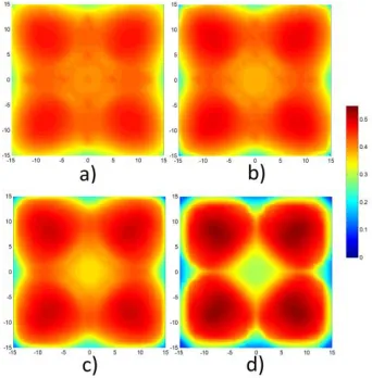
Fig. 4. FAST angular efficiency distribution for four different camera layouts as a function of the azimuth and elevation angle. The results can be interpreted by two numbers, the average FoV efficiency (for all elev. and azimuth angles) and the efficiency for the on-axis ray (0, 0 deg). X-on-axis represents the azimuth and Y-axis the elevation angles of the incident light. The colour scale is normalized between 0 – 1. An efficiency of 1 corresponds to the aperture input power. a) camera box only - 40.2%/25.0%, b) camera box with side mirrors - 41.2%/25.2%, c) camera box with side mirrors and central pyramid - 42.0%/40.2% and d) camera box with side mirrors, central pyramid and camera front panel diffuser - 43.6%/45.5%.
as a function of this distance was optimized to minimize the effect of the dead space between the PMTs (figure 5).
Fig. 5. FAST angular efficiency distribution for four different camera-mirror distances, with average efficiency value in FoV. X-axis is azimuth angle and Y-axis is elevation angle. Colour scale in relative value. 100 % is aperture input power. Mirror-camera distance of 710 mm was chosen as the best optical design for FAST.
a) 730 mm 41.1% / 41.0%, b) 720 mm 41.7% / 39%, c) 710 mm 42.0% / 35% and d) 690 mm 41.5%/32%.
5 Conclusion
Taking the FAST efficiency into consideration, a layout with side camera mirrors, a central pyramid, and camera front panel diffuser with a mirror-camera distance of 710 mm was chosen as the best optical design for FAST. The camera is slightly defocused to reduce the losses from the camera centre, and these results in a higher homogeneity of efficiency.
Acknowledgements
This work was supported by the Japan Society for the Promotion of Science through the Grant-in-Aid for
Young Scientist (A) 15H05443, Grant-in-Aid for JSPS Research Fellow 16J04564 and JSPS Fellowships H25-339, H28-4564. This work was partially carried out by the joint research program of the Institute for Cosmic Ray Research (ICRR), University of Tokyo. This work was supported in part by NSF grant PHY-1412261 and by the Kavli Institute for Cosmological Physics at the University of Chicago through grant NSF PHY-1125897 and an endowment from the Kavli Foundation and its founder Fred Kavli. The Czech authors gratefully acknowledge the support of the Ministry of Education, Youth and Sports of the Czech Republic project No. LM2015038, LTAUSA17078, EU/MSMT CZ.02.1.010.00.016 _0130001402 and EU/MSMT- CZ.02.1.01/0.0/0.0/17_049/0008422.
References
1. K.-H. Kampert, A.A. Watson and
A.A. Watson, Extensive Air
Showers and Ultra High-Energy Cosmic Rays: A Historical Review, Eur. Phys. J. H 37 (2012) 359 [arXiv:1207.4827].
2. K. Greisen, Phys. Rev. Lett. 16, 748
(1966);
3. G. T. Zatsepin, V. A. Kuzmin,
Pis’ma Zh. Eksp. Teor. Fiz. 4, 114 (1966) [JETP. Lett. 4, 78 (1966)]. 4. J. Abraham, et al., Properties and
performance of the prototype
instrument for the Pierre Auger
Observatory, Nucl. Instrum.
Methods A 523 (2004) 50–95. http://dx.doi.org/10.1016/j.nima.200 3.12.012.
5. H. Tokuno, et al., New air
fluorescence detectors employed in the telescope array experiment, Nucl. Instrum. Methods A 676 (2012) 54–65. arXiv:1201.0002.
6. Fujii, T.; et al. (FAST
ultra-high energy cosmic ray showers with a single-pixel fluorescence telescope. Astroparticle Phys, 2016, Vol. 74.
7. Mandát, D.; et al. (FAST
Collaboration): The prototype
opto-mechanical system for the
Fluorescence detector Array of Single-pixel Telescopes. J Instrum, 2017, Vol. 12.
8. Fujii, T.; et al. (FAST
Collaboration): First results from the
full-scale prototype for the
Fluorescence detector Array of
Single-pixel Telescopes. 35th
International Cosmic Ray
Conference ICRC 2017, The