1201 |
P a g e
AUTOMATION USING POWER LINE
COMMUNICATION
Miss. Kalyani Utpat
1, Prof. Pallavi Deshpande
21,2
Department of Electronics & Tele communication
Smt Kashibai Navale College of Engineering Pune. Maharashtra-413304 – (India)
ABSTRACT
Power Line communication is communication technologies that enable sending data over existing power cables.
Now a days power line is getting wide acceptance for sending control signals and communication signals. It has
the advantage of less initial expenses to establish a communication network. In this work it is demonstrated
power line can be used for transmitting data using simple power line communication interface. The results are
promising that power line can also be used for high speed data transfer. Note to practitioners- Wireless
communication has become very popular for data transmission. Wireless devices are operated by using storage
cell or utility power. Many Home automation products in market are device dependent. With wireless devices
huge investment is required to automate the complete home which is just function specific. These days security
is a serious issue. One can integrate all the functionalities to have affordable commercial product if data
transmission at high rate can be done on power line. The outcome of this work can become a part of such
product which can be plugged in to all devices which are connected to power line. Such method provides
affordable and integrated solution. If high speed data transmission is possible over power line a microcontroller
is the only device that can be programmed according to applications to make a product.
I. INTRODUCTION
In Power Line communication is communication technology that enables sending data over existing power
cables. Power line communication is communication technology that enables sending data over existing power
cable. The proposed system fulfills all requirements of today people. PLC get wide acceptance to send control
signal & communication signal. The main advantage of system is it has less initial expenses to establish
communication network. Hence the demonstrated power line can be used for transmitting digital data using
simple power line communication interface. Hence the result are favorable to power line. Can also be used for
high speed data transfer The wireless device are also interface by using remote which have Trans receiver the
use will easily send command to master controller. The communication between master and slave device is
power line communication. For Power line communication PLC
modem 1187 is used which transmit & receive serial knowledge at 9600 rate. Wireless devices are operated by
using storage cell or utility power. Many automation products in market are device dependent. These days
security is a serious issue. Ones can the system can implement all the functionalities to have affordable
commercial product if data transmission at high rate can be done on power line. To transmit electric power from
1202 |
P a g e
60 Hz power lines were design. Electrical power lines are usually classified into the high (>100kV), medium(1-100kV) and low (<1kV)voltage network. Power line communication which is also known as Power line carrier,
power line digital subscriber line (PDSL), mains communication, power-line telecommunications, or power line
networking (PLN) uses the existing electrical network for communication.
II. OBJECTIVE
1) The aim of home automation is to control home devices from a central control point.
2) In this project, we present the design and implementation of a low cost but yet flexible and secure RF remote
based home automation system.
3) The communication between the devices is wireless. The protocol between the units in the design is enhanced
to be suitable for most of the appliances.
4) The system is designed to be low cost and flexible with the increasing variety of devices to be controller
III. SYSTEM METHODOLOGY
In this project the system is mainly divided in two part one is master controller & other is slave controller. The
source information is generated through RF remote key. RF remote send key status to RF receiver which is
present in master controller. At that time PLC module in master controller act as transmitter & send this
command to receiver PLC module which is present in slave controller through existing AC power line. That key
1203 |
P a g e
IV. FLOWCHART
The Fig shows the flow of complete system. To overcome all drawbacks on literature survey the proposed
automation system is design. Here we use CC430f51 RF Trans receiver for sending wireless command to master
controller. Master controller require pulse transformer for detection of zero crossing. Zero crossing will be
detected on basis of interrupted by using transistor circuit. Data will transmit through Renesas RL78 series
controller on TTL level. Data will transmit only after detection of zero crossing. The transmission time for
power line communication will require 500msec. Data was successfully transmitted through power line to the
slave device. Slave device route the appliances by using relay circuit. Master controller send control command
to selected slave device particular address. Slave device control the addressed appliances. For that power line
communication no extra line will require. In master controller there is transformer which convert 230V to
15V.The output of transformer is given as input to zero crossing detection circuit. Zero crossing will be detected
on the basis of interrupt by using transistor circuit.While pressing any key on RF Remote (which is used to
control the slave device by sending command through power line communication), it send the key status to
Master device through wireless communication using TI’s CC430F5137 RF module. Data will transmit through
Renesas’s RL78 series controller on TTL level. Data will transmit only after detection of zero crossing. The
transmission time for power line communication will requires 500msec. Communication is on process.
Transmission LED is blinking, which indicate data is transmitted successfully. While pressing any key on RF
Remote (which is used to control the slave device by sending command through power line communication), it
send the key status to Master device through wireless communication using TI’s CC430F5137 RF module. The
1204 |
P a g e
RF Remote and send to microcontroller (Renesas’s R5F100AA). Through TTL level serial communication.Microcontroller sends the incoming key status to slave device through power line communication. For that we
are using PLC module which is communicate with microcontroller through TTL level serial communication.
Slave device receives the data from master and send to microcontroller through TTL level serial communication
and switch ON or OFF the particular relay.
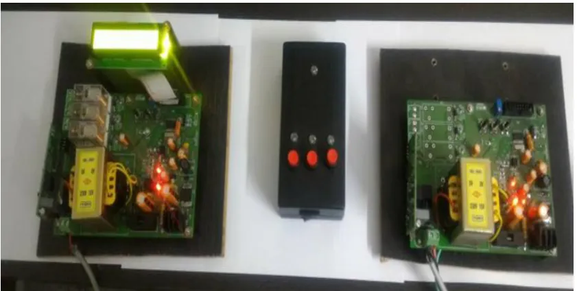
V. EXPERIMENTAL SETUP
The proposed system consist of mainly three parts. First part is master controller , second part is slave controller
& third part is remote device. Master controller consist of power line communication module, RF receiver
section & zero crossing circuit. Slave controller is consist of power line communication module, relay circuit &
display section. Remote is consist of RF transmitter and three number of operating key & On-Off key. Fig
shows the experimental setup of system.
Fig : Experimental Setup
VI.
INSTRUCTION FOR OPERATING THE SYSTEM
1. Start the system.
2. Wait for communication.
3. On the remote by using On/Off button.
4. To ON device 1 press key 1 from remote ,display shows RLY 1 ON .
5. To ON device 2 press key 2 from remote ,display shows RLY 2 ON .
6. To ON device 3 press key 3 from remote ,display shows RLY 3 ON .
7. To Off device 1 press key 1 from remote ,display shows RLY 1 OFF .
8. To ON device 2 press key 2 from remote ,display shows RLY 2 OFF .
9. To ON device 3 press key 3 from remote ,display shows RLY 3 ON .
1205 |
P a g e
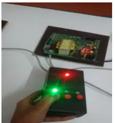
VII. RESULTS
The proposed system is divided in three parts Master, slave & remote. The slave device is having one LCD
display which shows actual result of proposed system . The Instruction is given by remote to On/ Off the
device. Following table gives results.
LED status of RF remote Message on Display of Slave device
Case I , key 1 press Led 1 ,On RLY 1 ON
Case II , key 2
press
Led 2 On RLY 2 ON
Case III , key 3 press Led 3 On RLY 3 ON
Following images displays the case 1 that is press key 1 on remote ,
Fig LED status of Remote key 1 press
Fig Relay 1 ON message
VIII. CONCLUSION
The proposed system provide full access control or automation of home / industry, without disturbing AC line
infrastructure. The instruction send to system is wireless as using RF remote and the communication between
master & slave is Power line communication. The system is inexpensive, easy to use.
REFERENCES
1206 |
P a g e
[2] &Android Wi Fi Device.” International Engineering Research Journal (IERJ) Volume 1 Issue 7 Page550-554, 2015, ISSN 2395-1621 .
[3] S.Venkatesulu1, L.Hemasundar, M.Sreeja, K.Divya, G.Jeevan Kumar, M.Bhogendranadh “Data
Transmission and Reception using Power Line Communication” International Journal of Research in
Advent Technology, Vol.2, No.4, April 2014 E-ISSN: 2321-9637
[4] Nagaraj Shet, Shreesha C “DATA TRANSMISSION THROUGH POWER LINE” Internal Journal of
Electronics and Communication Engineering & Technology (IJECET), ISSN 0976 –6464(Print), ISSN
0976 – 6472(Online), Volume 6, Issue 2, February (2015), pp. 25-34© IAEME
Derya Betul Unsal, Tankut Yalcinoz “Applications of New Power Line Communication Model for Smart Grids” International Journal of Computer and Electrical Engineering.
[5] Mingfue Li, Hung-Ju Lin “Design and Implementation of Smart Home Control Systems Based On Wireless
Sensor Network and Power Line Communications” , IEEE Transaction on Industrial Electronics, DOI
10.1109/TIE.2014.2379586.
[6] “Power-Line Communications (PLC) Integrated Analog Front-End Transceiver” Maxim Integrated.
[7] M. H. Savoji, “A Robust Algorithm for Accurate Endpointing of Speech Signals.” Speech Communication
8 (1989) pp 45-60.
[8] James M. Kates, “A Time-Domain Digital Cochlear Model.” IEEE Transactions on Signal Processing Vol.