Manufacturing Backend
Anusha Hiremath , Apoorva Dhavale , K V Roopa , Keertee Savadi, Aruna S. Nayak
Computer Science and Engineering and Technology BVB College of Engineering and Technology
Hubli, Karnataka, India
Abstract—‘ Manufacturing Backend’ is a software tool that is used to test the performance of a printed circuit board and store the related information in a centralized database which can be accessed easily. The setup contains seven computerized stations where each station performs a unique task in testing of a printed circuit board. Each printed circuit board is identified by a barcode which is read using a barcode scanner. There are totally seven stations and printed circuit board undergoes testing at each station. The tests that are carried out are voltage test, impedance test and sanity test. The information regarding each test is stored in a centralized database. The centralized database is accessible at all the stations. After the printed circuit board undergoes all the tests, it is cased and once again subjected to a functionality test. It will then be packed and ten such cased boards will be placed in a carton for shipping. The carton is identified by a new barcode and also contains barcodes of the ten boards. During the course of the series of tests, if any PCB is found to be defective, it is rejected. This tool is completely automatic. Since a centralized database is used, it reduces the overhead of storing and retrieving data for future use which makes it a versatile tool.
Keywords- Voltage test, Impedance test, Sanity test, Functionality test.
I. INTRODUCTION
The flaw free electronic product is a successful electronic product. With fast growing of technology, software when designed for a particular task, makes it efficient and user friendly in the business environment. When new software is developed, it must be tested thoroughly using techniques like white box testing and black box testing etc.,so that it must not create any problem at client side.
Similarly, even electronic products must undergo thorough testing to result in a snag free product. If the products are delivered to market without being tested completely, it may lead to problems to customers.
'Manufacturing Backend' is a software designed for a manufacturing company which produces electronic goods such as 'PCB'. A chip moulded on the PCB has to undergo various tests that are executed at seven different stations and their results are stored in a database. Each PCB has barcode on it as an identifier. The tests are voltage test, impedance test, sanity test and functionality test.
Station one executes voltage test, and voltage values are recorded. Impedance and sanity tests are accomplished in station two. The chip’s functionality is tested at station four. Casing of the PCB and its functionality after casing are examined at station five and six respectively.
The PCB’s which have completed the all the tests, are packed and placed in a carton. The carton contains ten
packed PCB’s. A new barcode value is generated for the carton and barcode values of ten PCB’s are placed on it. There are many Manufacturing Companies around the world, manufacturing electronic goods such as PCB, IC’s etc. A comparison study has been made with reference to Nexlogic and Norcott. Both are PCB manufacturers and a various tests are performed on them.
'Manufacturing Backend' is a sequential test line, where any type of PCB that has chip moulded on it comprising of memory (like microprocessor, microcontroller etc.,), is tested at various stations. It also identifies snags of PCBs and the defected product is rejected. The finished products are shipped to market to customers utility.
II. LITERATURE SURVEY
A. NEXLOGIC – HARNESS THE POWER OF ONE-STOP
Since 1995, NexLogic has established itself as a premier provider of PCB Design, PCB Fabrication, PCB Assembly, and Parts Procurement services. Before a PCB design arrives at the assembly stage, PCB testing is conducted. PCB testing consists of three major tests, Flying Probe Testing, ICT Testing, and Functional Testing. As a result, obvious and/or latent defects can be overlooked during assembly.
1) Flying Probe Testing:
Flying probe test development is a cost effective method and technique for providing a methodology for prototype verification. This eliminates enormous cost programming time and allows design changes with simple test program changes. Flying probes allow connection to test points and camera use for visual inspection.
Flying probe test is also capable of doing some power up testing by injecting signals at certain points on the board and detecting the output at other locations. Flying probes can access component pins directly or through automated test point probing without requiring test points, the improved test coverage over in-circuit tests that use beds-of-nails.
The use of flying probe technology provides a cost-effective solution. The new generation of flying probes stem from new and innovative ideas aimed at providing increased test speed, improved access, and greater fault coverage.[7]
2)
ICT Testing:ICT is ideal for mature products requiring high volume production. It runs the power signal to check voltage levels and resistance measurements at different nodes of the board. ICT is excellent at detecting parametric failures, design related faults and component failures.
3) Functional Testing:
Functional test (FCT) is used as a final manufacturing step. Functional testers typically interface to the PCB under test via its edge connector or a test-probe point. This testing simulates the final electrical environment in which the PCB will be used.
The most common form of functional test, known as “hot mock-up” simply verifies that the PCB is functioning properly. More sophisticated functional tests involve cycling the PCB through an exhaustive range of operational tests.
NexLogic consists of three major tests. Similarly the proposed system has four major tests, Impedance test, Voltage test, Sanity test and Functionality test and a centralized database to store the test results.
B. NORCOTT - Electronic Design & Manufacturing Norcott was formed in 1997 by the management team of Mosaic Technology, located at Cheshire. Norcott is providing electronic solutions to customers ranging from small technology companies to global blue-chip operations. The company provides a wide range of assembly services from engineering prototypes through to regular production volume – including wiring, complete box build and test. Norcott`s technology is such that it is capable of assembling a wide variety of components onto PCB substrates. Generally any combination of surface mount (SMT) and through-hole (PTH) components can be accommodated. [2] A dedicated Front End Engineer is allocated to each assembly job who is personally responsible for all aspects of a build and provide the primary customer contact for all engineering issues including the ubiquitous ‘last minute change’.
On receipt of the manufacturing data it is imported into Norcott’s engineering database. From the database any possible issue relating to PCB penalisation, DFM, footprints or component specification will be identified and discussed with customer before the manufacturing data is released to production.
Once PCBs have been completed they are functionally tested prior to mechanical integration or dispatch if requested by the customer.
Norcott has a manufacturing unit, a unit to handle database and the PCB is tested for functionality. Norcott offers a wide range of solutions to the programming of components prior or post assembly.
One time programmable (OTP) parts will normally be programmed and verified prior to assembly.
The proposed system includes usage of barcode as identifier for PCB and station wise execution of the testing and the stations are pipelined and includes a centralized database that can be accessed only by authorized persons.
III. PROPOSED METHOD
The proposed method is a software which is designed for performing tests on PCB’s and store their related information in a Centralized Database. PCB have unique identification and barcode is used as identifier. Tests are carried out in seven stations that are in pipeline and the defected PCB’s are rejected. The ideal PCB is delivered to customers.
IV. TESTS CARRIED IN THE PROCESS
A. Voltage Test
The voltage test for chip, which is moulded on PCB is achieved by connecting the cables of the multimeter to VCC and ground pin respectively. The values displayed on the screen of the multimeter gives the voltage of Chip. The value lying in between 2.5- 5 is a successful voltage test. The PCB is rejected for the unsuccessful Voltage Test. [9]
B. Impedance Test
Impedance is the measure of the opposition that a PCB presents to a current when a voltage is applied. It has input impedance and output impedance, both values are recorded with multimeter. The input impedance of chip moulded on PCB is the power flowing in the network. The output impedance of PCB is the opposition exhibited by chip’s output terminals to an alternating current (AC) of a particular frequency. [4]
Input impedance value should be greater than output impedance for the successful impedance test. The manufactured product failing this property results in rejection of PCB. [6]
C. Sanity Test
The purpose of a sanity test is to confirm that each storage location in a memory device is working. It commences with erasing the memory of chip and followed by verifying the basic memory is entirely blank, and is said to pass the test. The one type of memory chip problem can be encountered by some sort of physical or electrical damage to the chip after manufacture. [3]
The most common source of actual memory problems is the circuit board. Typical circuit board problems are problems with the wiring between the processor and memory device,missing memory chips, and improperly inserted memory chips. This results in unsuccessful of Sanity test, and the PCB is rejected. [10]
D. Functionality Test
The purpose of functionality test in manufacturing is to validate the proper functioning of the product hardware, and is free of defects. It provides a pass or fail determination of finished PCB’s before they are shipped, and is considered final step of Process.
V. EXPERIMENTAL DESIGN
This is regarding the testing of products (PCB) in a Manufacturing company which comprises of seven stations. Each station manages various tests sequentially.
Each PCB is engaged in each station for various tests. After successful result of test at respective station, the PCB is forwarded to next station for further tests. If the result of any test is found unsuccessful at any station, the particular PCB is rejected.
The mechanism is commenced with moulding of chip on PCB. Each PCB has a Barcode as unique value for identification. PCB is forwarded to stations to undergo tests from station to station successively. This comprises of seven stations and at every station barcode value is read through Barcode Scanner. The Barcode values are stored in a centralized database and products can be tracked using this. [8]
The process commences with station one which performs impedance test and voltage test and the test results are stored in the centralized database. These tests are conducted using USB-Multimeter. The voltage test is carried by connecting the cables of the multimeter to VCC and ground respectively. The value lying in between 2.5- 5 is a successful voltage test and the PCB is forwarded to next station. The PCB is rejected for the unsuccessful Voltage Test. [5] Input impedance and output impedance value is recorded with USB multimeter. Test is successful if Input impedance value is greater than output impedance value, else the product is rejected with the unsuccessful test. [6] PCB is forwarded to next station and undergoes sanity test and loading of program into the chip and the results are stored in the centralized database. The sanity test is the measure to check the memory of the PCB. The memory of the PCB is flushed to get free space and a programme compatible to the PCB`s language is dumped into the clean memory and if the programme executes as desired then the functionality test of the PCB is a success.
Now PCB is moved to station three and undergoes functionality test. Next the PCB is forwarded to station four where PCB is cased and the barcode value is placed on the cased PCB.
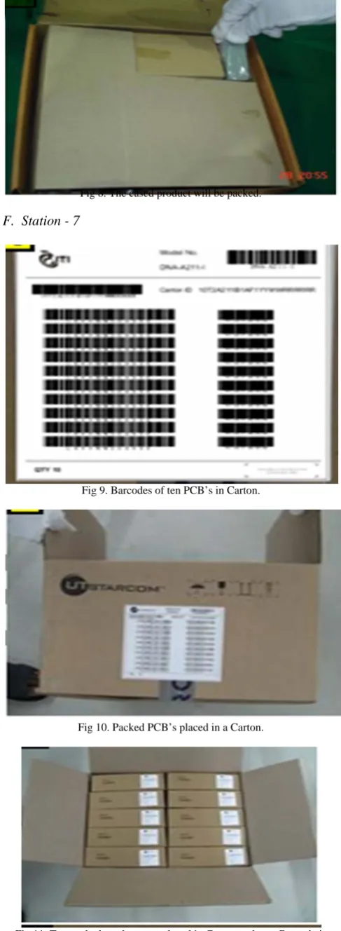
Station five checks for the functionality of the PCB, which is a final step of the manufacturing step. It provides a pass or fail determination of finished PCB’s before they are shipped. It validates the product hardware is snag free. Now cased PCB will be tested for functionality in station five and follows to station six for packing and the barcode is placed on pack. The packed product is forwarded to station seven, once it receives ten packed products, is placed in carton and a new barcode will be generated for the carton. The barcodes of ten packed products within the carton and the newly generated barcode for the carton will be put up on the carton. The carton is shipped to market for the utility of customers.
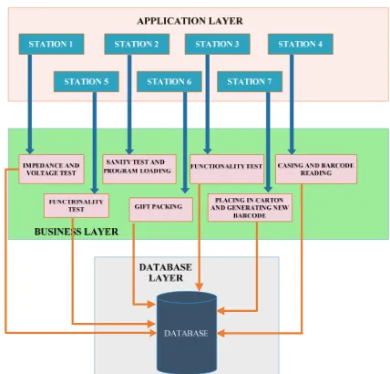
VI. ARCHITECTURE DESIGN
The architectural design includes three tiers: application tier, business tier and the database. Application Layer includes the user interface for the admin and user.
This layer has all the stations where user can choose the station to work on the product.
Business Tier includes Business logic of all the stations where product undergoes various tests. The results of all the tests performed on the product is stored in the Centralized Database. [1]
Fig 1. Logical Architecture of Manufacturing Backend
VII. EXPERIMENTAL ANALYSIS The step by step performing of tests on PCB are shown:
A. Station -1
Fig 2.This shows the electronic product which must be tested through seven stations. It has Barcode for the identification.
Fig 3. This shows the electronic product in PCB form. This is PCB which has chip to be tested that has ‘Barcode’ for its identification. The chip in
B. Station - 2
Fig 4. Sanity test completes the work of erase, blank check, program loading and verification, through RS232 cable connected to computer,
which is encircled.
C. Station - 3
Fig 5. A message ‘Successfully tested’ on LCD clears the functionality test.
D.Station - 4 and 5
Fig 6. The PCB is cased and Barcode is placed followed n Functionality Test.
E. Station - 6
Fig 7. : Packing of PCB in a Case.
Fig 8. The cased product will be packed.
F. Station - 7
Fig 9. Barcodes of ten PCB’s in Carton.
Fig 10. Packed PCB’s placed in a Carton.
VIII. CONCLUSION
Any manufacturing company needs to keep a backup of information of all the products it manufactures and sells. This software provides a basic idea how the information can be stored and used whenever required. Furthermore this process can be automatic by using conveyer belt on which products move continuously.
ACKNOWLEDGEMENT
We take pleasure in expressing our profound gratitude to everyone who have made a vital contribution in shaping our project. Our heartfelt thanks to Late Mr. Bob Connolly, COO at Asarva Chips and Technologies, Bengaluru, for having placed his confidence in us and giving us this project.
We would like to place on record our gratitude to our project guide Mrs. Aruna S.Nayak, for her continuous support and encouragement. We finally thank Dept of Computer Science and Engineering for providing the full support.
REFERENCES
[1] Vangie Beal ,”database definition” [online] Available at:
http://www.webopedia.com/TERM/D/database.html
[2] Norcott Electronic Design and Manufacturing, “information abou
company” [onine] Available at: http://www.norcott.co.uk/electronic-manufacturing-services/
[3] Micheal Barr, “software based memory testing ” [online] Available
at : http://www.esacademy.com/en/library/technical-articles-and-documents/miscellaneous/software-based-memory-testing.html
[4] “impedance definition” [online] Available
at:https://www.google.co.in/webhp?source=search_app&gws_rd=ssl #q=impedance&spell=1
[5] “Input impedance definition” [online] Available at:
http://en.wikipedia.org/wiki/Input_impedance
[6] “output impedance definition” [online] Available at:
http://en.wikipedia.org/wiki/Output_impedance
[7] Nexlogic printed circuit solutions, “information about company”
[online] Available at: , https://www.google.co.in/webhp?source=search_app&gws_rd=ssl#q
=NEXLOGIC
[8] “effective database management information” [online] Available at:
http://effectivedatabase.com/resources/why-should-you-have-a-centralized-system/
[9] Earl Boysen and Nancy C. Muir, “measuring stuff with a multimeter”
[online] Available at: http://www.dummies.com/how-to/content/measuring-stuff-with-a-multimeter.html
[10] “Boundary-scan test for memory interconnects” [online] Available