ABSTRACT
XIANG, PING. Toward Efficient SIMT Execution -- A Microarchitecture Perspective. (Under the direction of Dr. Huiyang Zhou.)
The design philosophy of many-core architectures such as graphics processing units (GPUs) is to exploit thread-level parallelism (TLP) to achieve high throughput. Compared to central processing unit (CPU) designs, GPU-like many-core architectures spend the on-die area mainly for computation rather than complex instruction processing, and therefore is more energy efficient.
In this dissertation, we identify several inefficiencies of current GPU design and proposal architectural designs for higher performance and better energy efficiency. First, I will first present our study on eliminating the computational redundancies within GPGPU. According to our study, there exists significant computational redundancy in SIMD execution, where different execution lanes operate on the same operand values. And besides redundancy within a uniform vector, different vectors can also have the identical values. Therefore, we propose detailed architecture designs to exploit both types of redundancy for performance improvements and energy savings. For redundancy within a uniform vector, we propose to either extend the vector register file with token bits or add a separate small scalar register file to eliminate redundant computations as well as redundant data storage. For redundancy across different uniform vectors, we adopt instruction reuse, proposed originally for CPU architectures, to detect and eliminate redundancy. The elimination of redundant computations and data storage leads to both significant energy savings and performance improvement. Furthermore, we propose to leverage such redundancy to protect arithmetic-logic units (ALUs) and register files against hardware errors.
to early finished warps are essentially wasted as they need to wait for the longest running warp in the same TB to finish. What is more, TB-level management can lead to resource fragmentation as well. To overcome these inefficiencies, we propose to allocate and release resources at the warp level. Warps are dispatched to an SM as long as it has sufficient resource for a warp rather than a TB. Furthermore, whenever a warp is completed, its resource is released and can accommodate a new warp. This way, we effectively increase the number of active warps without actually increasing the size of critical resources.
© Copyright 2014 Ping Xiang
Toward Efficient SIMT Execution -- A Microarchitecture Perspective
by Ping Xiang
A dissertation submitted to the Graduate Faculty of North Carolina State University
in partial fulfillment of the requirements for the degree of
Doctor of Philosophy
Computer Engineering
Raleigh, North Carolina
2014
APPROVED BY:
_______________________________ ________________________________ Eric Roternberg Frank Mueller
________________________________ ________________________________ Yan Solihin Huiyang Zhou
DEDICATION
BIOGRAPHY
Ping Xiang was born to in Jingmen, a beautiful city in the state of Hubei in China. He has obtained his BS degree from Huazhong University of Science and Technology(HUST), Wuhan, China in 2008, and his MS degree from University of Central Florida, in Orlando,US in 2010.
ACKNOWLEDGEMENTS
This dissertation would not have been possible without the help and support of a number of people. First and foremost, I would like to express my sincerest gratitude to my advisor, Dr. Huiyang Zhou, for the tremendous time, energy and wisdom he invested in my graduate education. His inspiring and constructive supervision has always been a constant source of encouragement for my study. I also want to thank my other thesis committee members, Dr. Eric Roternberg, Dr. Yan Solihin and Frank Mueller, for spending their time to review the manuscript and providing valuable comments.
I would like to thank my group members: Jingfei Kong, Martin Dimitrov, Yi Yang, and Saurabh Gupta. I want especially to thank Yi, who is my best friend and lab mate, for the inspiring discussions and sharing each step of graduate study with me. I would also like to give a special thanks to Jingfei, for his tremendous help during my graduate study. My enormous debt of gratitude goes to Saurabh Gupta, who proof-read my dissertation and provided many suggestions to help me improve it.
I dedicate this thesis to my family: my parents Xiaoxin Xiang and Yingxiang Ming, for all their love and encouragement through my life.
TABLE OF CONTENTS
LIST OF TABLES --- vii
LIST OF FIGURES --- xi
Chapter 1 --- 1
1. Introduction --- 1
Chapter 2 --- 3
2. Exploiting Uniform Vector Instructions for GPGPU Performance, Energy Efficiency, and Opportunistic Reliability Enhancement --- 3
2.1 Introduction --- 3
2.2 Background and Motivation --- 6
2.3 Architecture Design --- 10
2.4 Exploiting Intra-Warp Uniform Vector Instructions --- 12
2.5 Experimental Methodology --- 18
2.6 Experimental Results --- 19
2.7 Related Work --- 32
2.8 Conclusions --- 33
Chapter 3 --- 35
3. WarpMan: Warp-level Resource Management for High Throughput GPU Architecture --- 35
3.1 Itroduction --- 35
3.2 Bckground --- 37
3.3 Lmitations of Thread-block Level resource management --- 41
3.4 WapMan: WARP-Level Resource management --- 51
3.5 Experimental Methodology --- 56
3.6 Experimental Results --- 58
3.8 Conclusions --- 65
Chapter 4 --- 66
4. Revisiting ILP Designs for Throughput-Oriented GPGPU Architecture --- 66
4.1 Introduction --- 66
4.2 Background --- 69
4.3 Experimental Methodology --- 70
4.4 Instruction-level parallelism for shader cores --- 72
4.5 Heterogeneous GPU Architecture --- 87
4.6 Related Work --- 93
4.7 Conclusion --- 94
Chapter 5 --- 96
5. Locality Study on GPU Architecture --- 96
5.1 Introduction --- 97
5.2 Background --- 97
5.3 Locality Study on GPU applications --- 99
5.4 Coarse grained memory hierarchy for GPGPU --- 101
5.5 Experimental results --- 101
5.6 Conclusion --- 104
Chapter 6 --- 105
6. Conclusion --- 105
Publications --- 107
LIST OF FIGURES
Figure 1. A code example to illustrate both intra- and inter-warp uniform vector
instructions. ... 7 Figure 2 Percentage of redundant operations resulting from intra-and inter-warp
uniform vector instructions. ... 9 Figure 3. The baseline architecture of an SM. ... 11 Figure 4. Reusing the existing broadcast logic to feed the scalar value to multiple
SPs. ... 12 Figure 5. Performance gains from eliminating uniform vector instructions. The
token-based design is used to handle intra-warp uniform vector
instructions. ... 21 Figure 6. Performance gains from eliminating uniform vector instructions. The
SRF-based design is used to handle intra-warp uniform vector
instructions. ... 21 Figure 7. The ratio of extra copy instructions introduced over the overall number of
dynamic vector instructions. ... 23 Figure 8. Dynamic energy consumption of our approaches normalized over the
baseline GPU. ... 24 Figure 9. Normalized total energy consumption when using the token-based design
to handle intra-warp uniform vector instructions. ... 25 Figure 10. Normalized total energy consumption when using the SRF-based design
to handle intra-warp uniform vector instructions. ... 25 Figure 11. The performance impact of the SRF size. ... 26 Figure 12. The performance impact of the IRB size. ... 27 Figure 13. The performance improvement from eliminating uniform vector
instructions on a GPU with 15 SMs and 16 SPs per SM. ... 27 Figure 14. Reliability coverage of ALUs by leveraging the redundancy in uniform
vector instructions. ... 30 Figure 15. Reliability coverage of vector register files by leveraging the redundancy
in uniform vector instructions. ... 31 Figure 16. The overhead for redundancy checks in dynamic energy consumption. ... 32 Figure 17: A code example to confirm the TB-level resource management on GPUs ... 39 Figure 18: Starting and ending times for different TBs/warps on a GTX 680 GPU
for the kernel shown in Figure 1. (a) Starting times for different TBs. (b)
Figure 19: Starting and ending times for different TBs/warps on a GTX 480 GPU for the kernel shown in Figure 17. (a)Starting times for different TBs.
(b) Ending times for 32 warps in TB0. ... 40
Figure 20. The ratio of allocated number of registers over the total number of registers. The number besides the benchmark name is the number of TBs that can run on an SM, simultaneously. ... 43
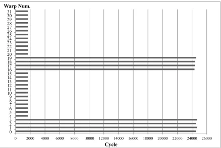
Figure 21. The lifetimes/execution times of different warps in TB0 of the benchmark RAY. The ratio of temporal resource underutilization (RTRU) is 49.7%. ... 44
Figure 22: A code segment from the benchmark RAY. ... 45
Figure 23: The histogram of per-warp dynamic instruction counts for the benchmark, RAY. The notation (a,b] means the range: {x|a<x<=b}. ... 45
Figure 24: A code example from the benchmark ST ... 46
Figure 25: The histogram of per-warp dynamic instruction counts for the benchmark ST. ... 47
Figure 26: The lifetimes/execution times of different warps in TB0 of the benchmark ST. The ratio of temporal resource underutilization (RTRU) is 70.1%. ... 48
Figure 27: The texture cache miss rate, measured in MPKI, of the different warps in TB (127, 23) of the benchmark CT. ... 49
Figure 28: The lifetime/execution time of different warps in TB (127, 23) of the benchmark CT. The ratio of temporal resource underutilization (RTRU) is 6.4%. ... 49
Figure 29: Warp-level divergence measured in the ratio of temporal resource underutilization (RTRU) for different warp scheduling policies. ... 51
Figure 30. Thread-block dispatching logic. ... 53
Figure 31. The workload buffer ... 55
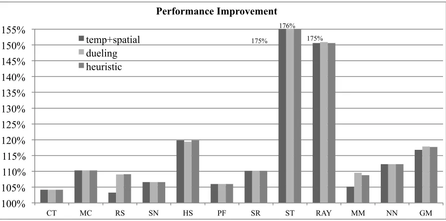
Figure 32: The performance improvements from our proposed approaches. ... 59
Figure 33: The performance improvement from the SM-dueling and the static threshold (labeled ‘heuristics’) approaches to eliminate the contention problem. ... 61
Figure 34: The total energy savings from our proposed approaches. ... 62
Figure 35: The performance improvement from our approaches when using the two-level warp scheduling policy. ... 62
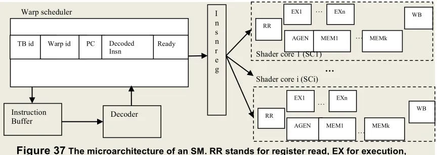
Figure 37 The microarchitecture of an SM. RR stands for register read, EX for execution, AGEN for address generation, WB for write back, multiple
EX or MEM stages account for multi-cycle latency. ... 69
Figure 38 Many-thread aware data bypassing.. ... 74
Figure 39. Architecture of (a) a many-thread aware scoreboard and (b) the associated warp scheduler. ... 75
Figure 40. Handling write-after-write data hazards with the no-match (NM) flag. ... 77
Figure 41. Branch prediction/resolution in SIMT architectures. The branch outcomes, if available at EX4 or EX8, can guard the execution or write back operations of the instruction from the predicted path. ... 80
Figure 42. The performance improvement of the ILP techniques to reduce data hazards ... 81
Figure 43 the performance improvements over baseline GPU for different number of scoreboard entries ... 82
Figure 44. Performance improvements from reducing data hazards on GPUs with different register file sizes. ... 83
Figure 45. The performance improvements from branch prediction on the baseline GPU equipped with the bypassing and scoreboard techniques. ... 84
Figure 46. Performance comparisons across different register file sizes. The legend: the number means the register file size and ‘_ILP/TLP’ means with/without ILP techniques. ... 85
Figure 47. The prediction accuracy for conditional non-divergent branches of different prediction schemes. ... 85
Figure 48. The performance of different GPUs running single kernels. ... 89
Figure 49. The energy consumption of different GPUs running single kernels ... 89
Figure 50. The performance of different GPUs running concurrent kernels (one favors ILP and the other favors TLP). ... 90
Figure 51. The energy consumption of different GPUs running concurrent kernels (one favors ILP and the other favors TLP). ... 90
Figure 52. The performance of different GPUs running concurrent kernels (one favors ILP and the other favors TLP). ... 92
Figure 53. The energy consumption of different GPUs running concurrent kernels (one favors ILP and the other favors TLP) ... 93
Figure 54 1: Locality plot for benchmark milc ... 98
Figure 55 Locality plot for benchmark Kmeans ... 99
Figure 57, performance improvements of our scheme, coarse2 means issuing 1 neighboring access in case of a miss, coarse4 means issue 3 neighboring
LIST OF TABLES
Table 1. The baseline GPU configuration. ... 18
Table 2. Area and energy consumption of the proposed components ... 18
Table 3. The benchmarks used for evaluation. ... 19
Table 4. The baseline GPU configuration. ... 57
Table 5. The benchmarks used for evaluation. ... 58
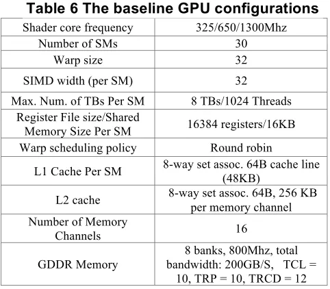
Table 6 The baseline GPU configurations ... 70
Table 7 . Workloads used in experiments ... 71
Chapter 1
1.
Introduction
However, as we found out, there still exists a significant amount of inefficiencies during the GPU execution. First, during SIMD execution, different threads in the same warp are supposed to operate upon different data. However, certain program structures in the kernel code, such as loops, and some intermediate computations, including loading data from the same address, calculating configuration numbers, or initializing registers with constant values, result in identical computations among the threads in a warp. In such cases, different threads in a warp have the same source values and therefore produce the same output. And we observe that such computational redundancy does not only exist among the threads within a warp, but also happens at the warp level. Therefore our first work focuses on addressing the computation redundancy issue within the GPGPU.
Chapter 2
2.
Exploiting Uniform Vector Instructions for
GPGPU Performance, Energy Efficiency, and
Opportunistic Reliability Enhancement
2.1
Introduction
approach to further improve the performance, energy efficiency and reliability of GPU computing.
Our approach is built upon the following observations on SIMT processing. During SIMD execution, different threads in the same warp are supposed to operate upon different data. However, certain program structures in the kernel code, such as loops, and some intermediate computations, including loading data from the same address, calculating configuration numbers, or initializing registers with constant values, result in identical computations among the threads in a warp. In such cases, different threads in a warp have the same source values and therefore produce the same output. This value locality was referred to as uniform vectors [9]. In this paper, we observe that such computational redundancy does not only exist among the threads within a warp, but also happens at the warp level. In other words, different warps may have identical input and output values. Therefore, we refer to them as intra-warp and inter-warp uniform vector instructions, respectively.
register is used as both a source and the destination operand. A register renaming table and a freelist are introduced to manage the SRF. Note that although register renaming apparently adds the complexity of instruction processing, it is done at the warp level, therefore the overhead is amortized by the high number of threads (e.g., 32) in a warp.
To detect and eliminate inter-warp redundancy, we leverage the idea of instruction reuse [51] and propose a warp-level instruction reuse buffer (IRB). When an instruction hits in the IRB, it skips execution and directly writes back the results stored in the IRB into the destination register. To reduce the complexity of the warp-level IRB, we choose to allow only the instructions, which are detected as intra-warp uniform, to access it. This eliminates the need for the IRB to store and compare the input values of all the threads in a warp.
We model our proposed designs in a cycle-accurate GPGPU architecture simulator and our experimental results show that our proposed deigns achieve significant energy savings, up to 25.3% and 12.7% on average, along with performance gains of up to 23.9% and 12.0% on average.
Since GPUs are getting more and more popular in general-purpose computations, there is a growing concern on reliability [14][52]. We propose to leverage both intra- and inter-warp uniform vector instructions for opportunistic reliability enhancement. For intra-warp uniform vector instructions, we simply use two threads to carry out the computations and store the two results to provide the necessary redundancy. For inter-warp uniform vector instructions, we choose to protect the warp-level IRB with parity bits. Our results show that our approach achieves 21.1% and 14.1% reliability coverage for ALUs and register files, respectively, with no performance penalty and only 0.29% dynamic energy overhead (or 0.14% in total energy) compared to our proposed designs that completely eliminate the redundancy from uniform vector instructions.
experimental methodology and results are discussed in Section 2.4 and Section 2.5, respectively. Related work is addressed in Section 2.6. Section 2.7 concludes the chapter.
2.2
Background and Motivation
Modern GPUs employ the SIMT programming model. A GPU program, commonly referred to as a kernel, follows the single-program multiple-data (SPMD) model. A kernel specifies the workloads of all threads and differentiates them using thread ids. The threads are organized into a two-level hierarchy. The kernel is launched to a GPU as a grid of threads, which contains multiple thread blocks/workgroups. Each thread block/workgroup in turn contains multiple warps/wavefronts. A warp/wavefront is a group of threads that are executed in the SIMD manner by sharing the PC.
In GPU hardware, a high number of cores are also organized in a hierarchy. Each GPU has multiple Streaming Multiprocessors (SMs) or Compute Units (CUs). Each SM/CU in turn has multiple streaming processors (SPs)/processing elements (PEs). The resources in each SM/CU include a vector register file, the shared memory, and L1 caches. The threads in the same thread block/workgroup will be executed on the same SM/CU so as to support synchronization and data exchange among the threads in the same thread block/workgroup. One SM can host one or more thread blocks depending on the resource requirement of each thread block.
its source operands, including the current active mask, are uniform vectors, it is called a uniform vector instruction.
Figure 1. A code example to illustrate both intra- and inter-warp uniform vector instructions.
The code in Figure 1 also shows that besides the identical computation (or redundancy) among the threads within a warp, there exist identical computations among different warps. For example, the computation on line 2 ‘blockIdx.x*blockDim.x’ only depends on thread block ids. All the warps in the same thread block will perform the same computation. In addition, the loop control on line 3 may also result in redundancy across different warps as long as one warp reaches the same loop iteration before another leaves it. Due to the commonly used round-robin warp scheduling policy [35], the warps in a thread block usually make similar progress. As a result, these warps tend to carry out identical loop iterator update and bound check operations. To differentiate identical computations within a warp and across multiple warps, we refine the definition of uniform vector instructions and refer to them as intra-warp uniform vector instructions and inter-warp uniform vector instructions.
In the current GPU architectures, both intra- and inter-warp uniform vector instructions result in redundant computations as well as redundant register file reads and writes since the exactly same computation is repeated for many threads in the same warp or different warps. As a warp/wavefront contains 32/64 threads in NVIDIA/AMD GPUs, one intra-warp uniform vector will lead to 31/63 redundant computations. To address this issue, a scalar unit is added to each CU in AMD’s latest Graphics Core Next (GCN) architecture [1] and it relies
1. __global__ void foo (float *A, float *B, float *C, int width) { 2. int idx = (blockIdx.x*blockDim.x+threadIdx.x);
on the compiler to identify the uniform vector instructions and to encode them as scalar instructions to be executed in the scalar unit. The scalar unit in AMD’s GCN architecture has a scalar register file, which can forward scalar register values to the SPs/PEs when they are used as source operands for vector instructions, and a scalar ALU to perform scalar computations.
Although the GCN architecture reduces redundant operations, several limitations remain. First, the scalar instructions are generated using the compiler and there are fundamental limitations of static analysis by the compiler. For example, the if-statement ‘if (B[idx]>0)’ on line 5 in Figure 1 may result in control divergence among the threads in a warp, i.e., some threads satisfy the condition while others do not. Therefore, the compiler cannot classify the operations ‘b = C[i]’ on line 6 and ‘b = 0’ on line 8 as scalar operations although they do not have data dependence on the thread id. In other words, the control dependency on thread id makes the static analysis very challenging. Second, the scalar unit incurs additional hardware cost and the dedicated scalar instructions are not compatible with previous GPUs with the same vector instruction set architecture (ISA). Third, the AMD GCN cannot handle inter-warp uniform vectors since the scalar instructions are embedded in the same instruction stream as vector operations, which are executed separately for each warp.
numbers of redundant operations to the total number of dynamic scalar instructions and report the ratios in Figure 2. The reason why we do not use the number of vector instructions is due to the presence of control divergence. In such a case, the number of scalar instructions captures the application’s computational needs more accurately than the number of vector instructions. Note that in our redundant instruction statistics, we do not include branch instructions as the PC is already updated at a per-warp basis in SIMT architectures. Memory instructions are not considered as redundant operations either as we assume the memory coalescing logic and miss status handling registers (MSHRs) already detect/merge redundant memory requests.
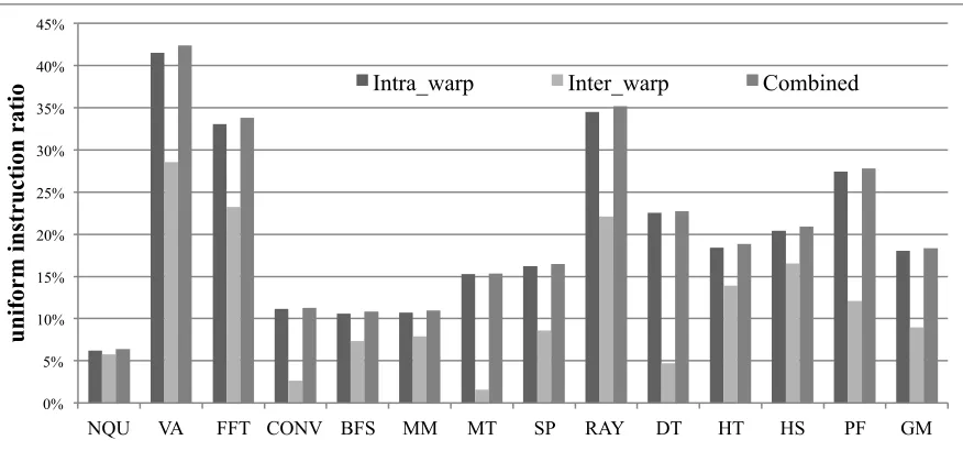
Figure 2 Percentage of redundant operations resulting from intra-and inter-warp uniform vector instructions.
As we can see from Figure 2, among the 13 applications under our study, there exist significant redundant operations. The contribution from intra-warp uniform vector instructions can be as high as 41.5% and 18.1% on average using the geometric mean (GM). The inter-warp uniform vector instructions also result in up to 28.5% and an average of 8.9% redundant operations. When both types are combined, up to 42.4% and an average of 18.4% of all scalar operations are redundant. Although the difference between intra-warp and
0% 5% 10% 15% 20% 25% 30% 35% 40% 45%
NQU VA FFT CONV BFS MM MT SP RAY DT HT HS PF GM
u n ifor m i n str u cti on r ati
combined intra- and inter-warp results is apparently small, it does not mean that the contribution from inter-warp uniform vector instruction would be low. The reason is that we only count 1 redundant scalar operation for each inter-warp uniform vector instruction as discussed above. As shown in Section 2.5, eliminating redundancy from inter-warp uniform vector instructions can lead to significant performance gains and energy savings even after we already leverage intra-warp uniform vector instructions.
2.3
Architecture Design
Figure 3. The baseline architecture of an SM.
The number of EX stage depends on the instruction latency.
As shown in Figure 3, there is a warp scheduler in an SM and it issues instructions from the ‘ready’ warps, meaning that they have all the source operands ready for their current instructions. During the register read (RR) stage, the multi-lane vector register file (VRF) is accessed to provide the source operands for each thread in the warp. The aggregated registers from all the threads in a warp can be viewed as a vector register. For example, for an instruction ‘ADD r1, r2, r3’, the register r1 for all the threads in warp can be viewed as a vector register VR1, which contains 32 scalar registers. Here, we use the notation ‘VR1.i’ to denote the scalar register r1 of the ith thread in a warp. Depending on the number of SPs (denoted as ‘NumSP’) in an SM, which are used for executing instructions from a warp, the warp scheduler issues one instruction to the SPs every ‘warpsize/NumSP’ cycles. In NVIDIA GTX285 GPUs, NumSP is 8, and in GTX480 (aka Fermi architecture), NumSP is 16 as each warp occupies 16 SP lanes. Typically, the threads in a warp are assigned to the SPs in a round-robin manner. In other words, if NumSP is 8, the first SP (i.e., SP0) executes the instruction for thread 0, 8, 16, 24; the second SP executes thread 1, 9, 17, 25; etc. Also, the VRF lane in each SP provides the corresponding register operands. For example, with 8 SPs in an SM, the VRF lane in SP0 provides VR1.0, VR1.8, VR1.16, and VR1.24. The warp id in the warp scheduler is used to map the same architectural registers in different warps into different physical vector registers.
Warp scheduler
PC decoded insn
Insn.
Buffer Decoder
...
.
Vector Register File
IF ID RR EXn WB id
2.4
Exploiting Intra-Warp Uniform Vector Instructions
To detect intra-warp uniform vectors, we start with the instruction decode (ID) stage in the GPU pipeline. During the ID stage, an instruction’s source operands are checked to see whether they are uniform vectors. If an operand is an immediate or a special register used for thread id independent information such as thread block dimensions, it is detected as a uniform vector. An instruction is detected as a uniform vector instruction if all its source operands are uniform and the current active mask is all 1’s, indicating that the instruction is not under a control divergent path. In this case, the destination register will be a uniform vector. Next, we propose two architectural designs to implement the propagation of uniform vectors. The two designs differ in where to store uniform vectors. One reuses the VRF and extends it with token bits. The other introduces a small scalar register file (SRF) to replace VRF accesses with SRF accesses.
2.4.1 Token-based design
In this design, we add a token file, which contains 1 token bit for each vector register. A token bit is set in two scenarios: (1) when a uniform vector instruction is detected and is updating its destination vector register, and (2) when the value to be written back is from the broadcast path even the instruction is not yet detected as uniform. The broadcast path, which is used for accessing the same address in either shared memory or global memory, ensures that all the threads in the warp will have the same value. A token bit is reset when the corresponding vector register is redefined by a regular (i.e., non-uniform) vector instruction.
Figure 4. Reusing the existing broadcast logic to feed the scalar value to multiple SPs.
... ...
Broadcast bus SP
The token file will be accessed during the ID stage to determine whether an instruction is a uniform vector one. If so, once this instruction is issued, it does not need to update all the 32 scalar registers in the destination vector register. Instead, updating one of them is sufficient. As this vector register can be used as a source operand of a non-uniform vector instruction, we add a MUX to reuse the existing broadcast bus, as shown in Figure 4, to provide the data. This way, an intra-warp uniform vector instruction is essentially converted to a scalar one. Compared to a regular vector instruction, it saves (warpsize – 1) computations as well as the associated read and write accesses to the VRF lanes.
Another important advantage of converting a uniform vector instruction into a scalar one is the opportunity to improve instruction issue rate. As our uniform vector instruction detection happens in the ID stage, the warp scheduler can increase the issue rate from one per ‘warpsize/NumSP’ cycle to one every cycle for uniform vector instructions. In other words, after a uniform vector instruction, which is converted to a scalar one, is issued, the warp scheduler can issue another ready instruction in the next cycle.
all the threads in a warp will be executed at the same time, this hazard disappears naturally and the formula can still be used to specify VRx.0 to be used for the scalar value. Note that for the instruction ‘Add VR1, VR1, #2’ with the token bit set for VR1, there is no hazard since this instruction will be detected as a uniform vector instruction. The token bit will remain set and only the ALU in SP0 will be used to carry out the computation (VR1.24 = VR1.24 + #2).
Second, control divergence complicates the processing of uniform vectors. Consider the case with the instruction ‘VR1 = VR1 + 2’ with the token bit of VR1 set and the active mask indicates that only threads 24-31 are to be executed in a warp. Although our intra-warp uniform vector instruction detection logic will detect it as a non-uniform vector instruction due to the condition on the active mask, there still is a correctness issue. The reason is that the scalar value VR1.24 will be overwritten with ‘VR1.24+2’ and for threads 0 to 23, the register VR1’s value would be corrupted. To resolve this problem, we propose the following copy-on-write solution. When the warp scheduler finds that the current instruction is under a control divergent path by checking the active mask and the instruction has its destination register being the same as one of its source uniform vector operands, the warp scheduler inserts a copy instruction, which explicitly copies the scalar value of the uniform vector to all of its scalar registers. This way, all the threads have their private copy of the register and the correctness is ensured. As we show in Section 2.5.1, this copy-on-write happens fairly infrequently, resulting in negligible performance overhead.
2.4.2 Scalar register file based design
registers or 512/1024 vector registers). Each access incurs nontrivial energy consumption. Using a small scalar register file reduces the energy consumption at a small area overhead.
To manage the SRF, we add a freelist and a renaming map table to dynamically allocate and free the scalar registers in the SRF. In the ID stage, the renaming map table is accessed to see whether its source vector register operands are remapped to scalar registers. For a detected uniform vector instruction, its destination vector register will be renamed by obtaining a scalar register from the freelist and updating the renaming map table accordingly. Decoded and renamed instructions will be kept in the warp scheduler waiting to be issued to the SPs. During instruction execution, the renamed register operands specify whether the SRF or the VRF is to be accessed. For an intra-warp uniform vector instruction, both its source and destination registers will be from the SRF. In this case, the ALU of the first SP is reused to carry out the computation. The register renaming logic may affect the timing of the ID stage and lead to an additional register renaming stage. Such a new pipeline stage at the frontend will not increase pipeline hazards, thereby having very limited performance impact as confirmed in our experiments.
The SRF is also connected to the existing broadcast path to handle the case when a scalar register is needed for a regular vector instruction. For a regular vector instruction, its destination vector register number will be used to check the renaming map table at the ID stage. If this vector register is currently being mapped to a scalar register, the mapping information will be cleared and the scalar register is pushed back to the freelist.
Our SRF-based design simplifies the processing of the corner case where the destination and a source operand share the same register, like in the case of ‘VR1 = VR1 + VR2’ where VR1 is currently mapped to a scalar register, e.g., SR4, but VR2 is not. With the renaming process, the instruction becomes ‘VR1 = SR4 + VR2’. During execution, the value of SR4 is broadcasted to all the SPs from the SRF. Since SR4 will not be overwritten during the execution, the correctness is ensured.
source operand, which is currently mapped to a scalar register. In other words, for the instruction ‘VR1 = VR1 + 2’ under a control divergent path with VR1 being currently mapped a scalar register SR5, the warp scheduler will insert a copy instruction ‘VR1 = SR5’, before issuing the instruction ‘VR1 = VR1 + 2’.
Note that our renaming process is based on physical vector register numbers. For the same architectural register, different warps map them to different physical vector registers based on their warp ids. Therefore, there is no conflict among the warps when the same registers are used.
Compared to the token-based design, the disadvantage of the SRF-based design is that due to the SRF’s limited size, when all the scalar registers are used up, we cannot convert newly detected intra-warp uniform vector instructions to scalar ones until a scalar register is freed to the freelist. We study this structural hazard effect in Section 2.5.3.
2.4.3 Exploiting Inter-Warp Uniform Vector Instructions
Different warps may perform the same computations. To exploit such inter-warp uniform vector instructions, we propose to leverage the idea of instruction reuse [51], which was proposed to reduce repeating computations in CPU architecture. In each SM, we add an instruction reuse buffer (IRB), which is a cache structure with the partial PC as the tag. Each entry in the data store includes opcode, three source operand values and one destination operand value. Here, we focus on instruction reuse only for intra-warp uniform vector instructions. Otherwise, for an arbitrary vector instruction, we have to compare the source operands for all 32 threads with those stored in the IRB, which would incur too much overhead. Partial PCs are used as tags to reduce the power consumption of fully associative searches. To avoid possible aliases due to partial PC match, we include the opcode field in the data store since identical inputs and opcode ensure the same outputs. Therefore, a hit in IRB means that both the partial PC and opcode match.
design is used. If all the source operands match, the execution stage will be skipped and the destination operand value from the IRB will be used to update either the first lane of the VRF or the SRF. If the source operand values do not match, the instruction will be executed in the first SP and the result will be used to update the corresponding IRB entry. If the PC misses in the IRB, the least-recently-used (LRU) replacement policy is used to find a victim entry in the IRB.
2.4.4 Leveraging Uniform Vector Instructions for Reliability Enhancement
As discussed in previous section, reliability is an important issue for general purpose computation on GPUs (GPGPU). Both intra- and inter-warp uniform vector instructions can be leveraged for hardware error detection. For intra-warp uniform vector instructions, we choose to use two vector lanes (or two SPs) to carry out the computation and compare them before updating the register file. Furthermore, we also store two copies of a scalar value to protect the VRF against errors. In our token-based design, the two copies can be stored in the first two lanes of the VRF. For our SRF-based design, one copy is stored in the SRF and the other is stored in the first lane of the VRF. Adding parity bits to each 32-bit scalar value is another option to detect errors in either the VRF or the SRF. Redundant data storage, however, adds error correction capability when used together with the parity protection: when two copies differ, the parity bit detects which one is uncorrupted.
For inter-warp uniform vector instructions, we propose to protect the IRB with parity bits so as to protect the ALUs in an indirect manner. In this scheme, we add 1 parity bit for each IRB entry. For an instruction with uniform vector operands, if its PC hits in the IRB and an error is detected in the IRB entry using the parity bit, the instruction will be executed and the IRB will be updated accordingly. When there is no error detected in IRB, the ALU computation is skipped. This way, the ALUs become less vulnerable to errors as they are being used less often to carry out computations.
2.5
Experimental Methodology
We modified GPGPUsim V3.0.1 [4] to model our proposed schemes to exploit intra- and inter-warp uniform vector instructions. Our baseline GPU configuration, modeled based on NVIDIA GTX285 GPUs, is shown in Table 1. The default SIMD width (or NumSP) is 8 and we vary this parameter in Section 2.5.3. In our experiments, we use an 8-entry IRB for inter-warp uniform vector instructions. Each IRB entry contains a 10-bit partial PC as the tag, three 32-bit source values, one 32-bit destination value, a 3-bit LRU field, and an 8-bit opcode field. In total, the hardware overhead of an instruction reuse buffer is 8*(10 + 3*32 + 32 + 3 + 8) = 1192 bits. For our SRF-based design, a SRF of 128 scalar registers (= 128*32 = 4096 bits) and a renaming table of 512 entries (512*7=3584 bits) are used. Compared to other resources shown in Table 1, such hardware overhead is quite limited. We examine the impact of these parameters in Section 2.5.3.
Table 1. The baseline GPU configuration. Shader core frequency 1.3GHz
Number of SMs 30
Warp size 32
SIMD width(i.e., NumSP) 8 /16 Max. num. of thread
blocks/threads per SM 8 thread blocks/1024 threads
Register file 64KB
Shared memory 16 KB
L1 cache 8-way set assoc. 64B cache block (48KB in total) L2 Cache 8-way set assoc. 64B (256kb per
MEM channel) Number of MEM channels 16
GDDR Memory 8 banks, 800Mhz, total bandwidth: 200GB/S, TCL =
10, TRP = 10, TRCD = 12
Table 2. Area and energy consumption of the proposed components
Area
(mm2) Static Power (W) Energy per access/operation (J) VRF 2.44 0.09 2.46/5.82 E -12 SRF 0.005 0.001 1.76/1.62 E -13
accesses, the number of IRB accesses and the number of SRF accesses. We then modified McPAT [36] using the similar approach to GPUWattch [33] to compute the area overhead and energy/power consumption. The resulting area and the energy per access of the VRF and the SRF using the 40nm technology are shown in Table 2. The energy consumption for different ALU operations is extracted from GPUWattch.
We select 13 benchmarks from Nvidia CUDA SDK [45], the Rodinia benchmark suite [8] and GPGPUsim to cover a wide range of application domains. The inputs to the benchmarks, the total number of scalar instructions as well as the baseline performance measured with instructions per cycle (IPC) are shown in Table 3.
Table 3. The benchmarks used for evaluation.
Benchmarks Inputs Total inst. IPC
N-Queen solver (NQU) 32 0.78M 89.3
Vector add (VA) (512, 512) 5.5M 207.5
Fast Fourier Trans. (FFT) (128, 128) 14M 164.1
Convolution (CONV) (512, 512) 157M 220.2
Breadth first search (BFS) 4096 11M 12.2
Matrix Multiply (MM) (128,80) 2M 135.2
MersenneTwister (MT) 48000000 1478M 122.9
ScalarProduct (SP) 524288 28M 177.1
Ray Tracing (RAY) (512, 512) 123M 193.6
dxtc (DT) 1024 573M 215.6
HeartWall(HT) (512,1) 4M 169.8
HotSpot (HS) (512, 2, 2) 103M 182.3
PathFinder(PF) 100000 582M 209.0
2.6
Experimental Results
2.6.1 Performance Impact from Eliminating Uniform Vector Instructions
uniform vector instructions are exploited (labeled ‘Inter), and when both are exploited (‘labeled ‘Combined’). When exploiting only inter-warp uniform vector instructions, either the token-based design or the SRF-based design is still used for detecting intra-warp uniform vector instructions. However, if such an intra-warp uniform vector instruction does not hit in the IRB, it is not converted to scalar operations so as to isolate the performance impacts.
Figure 5. Performance gains from eliminating uniform vector instructions. The token-based design is used to handle intra-warp uniform vector instructions.
Figure 6. Performance gains from eliminating uniform vector instructions. The SRF-based design is used to handle intra-warp uniform vector instructions.
Between the token-based and the SRF-based designs, most benchmarks show similar performance gains from eliminating intra-warp uniform vector instructions, except a few like CONV, SP, and PF. The reason is that the detected intra-warp uniform instructions in these benchmarks define many different vector registers. Therefore, there is a high pressure on the SRF. Once the SRF is used up, subsequently detected intra-warp uniform vector instructions are not utilized. In Section 2.5.3, we show that these benchmarks require a 256-entry SRF to achieve similar performance to the token-based design. On average using GM, leveraging
100% 102% 104% 106% 108% 110% 112% 114% 116% 118% 120% 122% 124%
NQU VA FFT CONV BFS MM MT SP RAY DT HT HS PF GM
Normalized Performance Intra Inter Combined
100% 102% 104% 106% 108% 110% 112% 114% 116% 118% 120% 122% 124%
NQU VA FFT CONV BFS MM MT SP RAY DT HT HS PF GM
intra-warp uniform vector instructions using the token-based design and the SRF-based design achieves 7.4% and 6.7% performance improvement, respectively.
For inter-warp uniform vector instructions, our proposed IRB can reduce the execution latency as well as improve the instruction issue rate, as discussed in Section 2.3.2. Among the benchmarks, FFT, RAY, HS and PF, show impressive performance gains as they have significant amount of inter-warp uniform vector instructions and most of them are long latency ones. In general, the performance gains closely follow the ratio of the inter-warp uniform vector instructions, shown in Figure 2. The only exception is VA. Although VA has a high inter-warp uniform vector instruction ratio of 28.5%, the performance gain from skipping them is 7.3%. The reason is that most of these instructions are short latency ALU operations such as SHL (shift left) and AND, while the overall performance for VA is dominated by memory bandwidth. As discussed in Section 2.3.2, the IRB is only accessed when an instruction has been detected as an intra-warp uniform vector instruction. Therefore, different designs to detect intra-warp uniform vector instructions also have an impact on IRB effectiveness. As the token-based design captures more intra-warp uniform vector instructions, there are more hits in the IRB, thereby performing better than the SRF-based design. On average, exploiting only inter-warp uniform vector instruction achieves the performance gains of 8.1% and 7.2%, using the token-based design and the SRF-based design, respectively.
IPC of 32. Similarly, for an intra-warp uniform vector instruction, it takes one cycle to issue rather than 4 cycles, which also essentially increases the IPC from 8 to 32 for this cycle.
As discussed in Section 2.2.3, in the case of a uniform vector register re-define under a control divergent path, we resort to our proposed copy-on-write solution. This leads to one extra copy instruction to be issued and executed. Next, we examine how often such cases happen. In Figure 7, we report the ratio of the overall number of copy instructions inserted over the overall number of dynamic vector instructions. From the figure, we can see that many benchmarks have no such cases. The benchmark FFT has the highest ratio of 0.044% and the average is 0.010%. Therefore, there is no noticeable impact from these extra copy instructions.
Figure 7. The ratio of extra copy instructions introduced over the overall number of dynamic vector instructions.
2.6.2 Energy Savings from Eliminating Uniform Vector Instructions
Our proposed schemes achieve energy savings in three ways: (a) reducing execution time results in static energy savings, (b) converting an intra-warp uniform vector instruction to a scalar one eliminates (warpsize – 1) redundant computations as well as associated register file accesses, and (c) eliminating an inter-warp uniform vector instruction eliminate 1 computation. We first look into the dynamic energy consumption and show the normalized
0.00% 0.01% 0.02% 0.03% 0.04% 0.05%
NQU VA FFT CONV BFS MM MT SP RAY DT HT HS PF GM
results over the baseline GPU in Figure 8 for both the token-based design (‘labeled ‘token’) and the SRF-based design (labeled ‘SRF’).
From Figure 8, we can see that eliminating both intra- and inter-warp redundant operations results in an average of 14.7% and 13.6% dynamic energy reduction using the SRF-based design and the token-based design, respectively. The SRF-based design saves more dynamic energy than the token based design. The reason is that the SRF-based design replaces VRF accesses with SRF accesses. Among the benchmarks, the benchmark, VA, has the highest dynamic energy reduction (36.0%) due to its high ratio (42.4%) of redundant operations shown in Figure 2.
Figure 8. Dynamic energy consumption of our approaches normalized over the baseline GPU.
The structures that we introduced for our approaches, including the 8-entry IRB and the 128-entry SRB, are quite small, less than 0.01% based on the area estimation using McPAT, compared to existing the 8 ALUs, the VRF, and caches in an SM. Therefore, the static energy savings follows very closely with the execution time reduction or performance gains. As a result, we only show the total energy consumption for our two designs in Figures 9 and 10. Similar to our performance results, we also report the normalized energy consumption for the case when only the intra-warp uniform vector instructions are exploited (labeled ‘Intra’), and when only the inter-warp uniform vector instructions are exploited (labeled ‘Inter’), and when both types of uniform vector instructions are exploited (labeled ‘Combined’).
30% 40% 50% 60% 70% 80% 90% 100%
NQU VA FFT CONV BFS MM MT SP RAY DT HT HS PF GM
Normalized dynamic energy consumption
Figure 9. Normalized total energy consumption when using the token-based design to handle intra-warp uniform vector instructions.
Figure 10. Normalized total energy consumption when using the SRF-based design to handle intra-warp uniform vector instructions.
From Figures 9 and 10, we can see that the intra-warp uniform vector instruction removal reduces the total energy consumption by 9.8% and 10.3% on average, for the token-based design and the SRF-based design, respectively. Eliminating inter-warp uniform vector instructions reduces the total energy consumption by 8.0% and 7.6%, for the two designs, respectively. When both intra- and inter-warp uniform vector instructions are exploited, the token design shows slightly higher energy saving (12.7%) than the SRF design (12.2%).
2.6.3 Design Space Exploration
60% 65% 70% 75% 80% 85% 90% 95% 100%
NQU VA FFT CONV BFS MM MT SP RAY DT HT HS PF GM
Normalized total energy consumption
Intra Inter Combined
60% 65% 70% 75% 80% 85% 90% 95% 100%
NQU VA FFT CONV BFS MM MT SP RAY DT HT HS PF GM
Normalized total energy consumption
Figure 11. The performance impact of the SRF size.
In our first experiment, we analyze the impact of the SRF size in the SRF-based design. We vary the SRF from 16to 256 registers. The results in Figure 11 show that for many of the applications including NQU, VA, FFT, BFS, MM, MT, RAY and DT, a SRF with 64 entries captures most of the uniform vector instructions. For remaining workloads, including CONV, HT, HS SP, and PF, the performance improves as we increase the number of entries. A 256-entry SRF performs almost the same as the unlimited one, which is equivalent to our token-based design.
In our second experiment, we analyze the performance impact of IRB. We vary the IRB size from 2 to 16 and the results in Figure 12 show that the average performance gains of the token-based design are 10.8%, 11.5%, 12.0% and 12.3% for the IRB size of 2, 4, 8 and 16, respectively. Therefore, we choose the reuse buffer size as 8 as the cost effective solution. The key reason why small IRBs (even with 2 entries) work well is that different warps make similar progress under the round-robin scheduling policy. After one inter-warp uniform vector instruction is detected from a leading warp and stored in the IRB, it will be quickly used by other warps. It is seldom the case that the warps have such different execution speeds that different warps detect and use a highly different set of inter-warp uniform vector instructions.
100% 102% 104% 106% 108% 110% 112% 114% 116% 118% 120% 122% 124%
NQU VA FFT CONV BFS MM MT SP RAY DT HT HS PF GM Normalized Performance
SRF_16 SRF_32
SRF_64 SRF_128
Figure 12. The performance impact of the IRB size.
In our third experiment, we investigate the impact of SIMD width (i.e., NumSP) on the effectiveness of our proposed approaches. In order to keep the same ALU-to-MEM bandwidth ratio when we increase NumSP from 8 to 16 (i.e., there are 16 SPs in each SM), we reduce the number of SMs from 30 to 15. The performance gains from eliminating only intra-warp uniform vector instructions (labeled ‘Intra’), from eliminating only inter-warp uniform vector instructions (labeled ‘Inter’), and eliminating both types of uniform vector instructions (labeled ‘Combined’) using the token-based design are shown in Figure 13. Here, the performance improvement is over the GPU with 15 SMs and 16 SPs per SM.
Figure 13. The performance improvement from eliminating uniform vector instructions on a GPU with 15 SMs and 16 SPs per SM.
100% 105% 110% 115% 120% 125%
NQU VA FFT CONV BFS MM MT SP RAY DT HT HS PF GM
Normalized Performance
IRB_2 IRB_4 IRB_8 IRB_16
95% 100% 105% 110% 115% 120% 125%
NQU VA FFT CONV BFS MM MT SP RAY DT HT HS PF GM
Normalized Performance
From Figure 13, we can see that when NumSP is increased to 16, the performance gains from eliminating intra-warp uniform vector instructions become marginal. There are two reasons for this impact. First, with NumSP increased from 8 to 16, the baseline instruction issue rate is improved from one instruction every four cycles into one instruction every two cycles. Although converting an intra-warp uniform vector instruction into a scalar one can improve the issue rate to one instruction every cycle, the room for improvement is reduced. Second, as each SM has more SPs, it requires more concurrent threads to run on each SM to fully utilize the increased number of SPs. Therefore, the insufficient TLP becomes the performance bottleneck rather than the instruction issue rate. On the other hand, with increased NumSP, we are able to achieve higher performance benefits from exploiting inter-warp uniform vector instructions for most benchmarks. The reason is that with more SPs, each SM requires more concurrent threads to hide execution latencies. For example, considering an instruction with 4 cycle latency, with 8 SPs per SM, the execution latency can be completely hidden when there is just 1 warp running on the SM. With 16 SPs per SM, in comparison, it requires 2 warps to hide the 4 cycle execution latency. With our IRB approach, if an instruction hits in the IRB, its execution can be skipped and the latency is reduced to 1 cycle. Therefore, it lowers the requirement on TLP and becomes more beneficial. One interesting anomaly is the benchmark MT, for which exploiting inter-warp uniform vector instructions leads to a 3.1% performance degradation. We looked into this benchmark and discovered that the performance loss is due to longer memory access latency resulting from decreased DRAM row access locality [31]. The DRAM row access locality means the average number of row accesses after a row is activated. The reason for such reduced row access locality is due to the fact that with our IRB approach, some warps, if their instructions hit in the IRB, make faster progress than others. Combined with the round-robin scheduling policy, the memory access sequence from different warps is altered, leading to such an anomaly.
eliminating only inter-warp uniform vector instruction, and from eliminating both types of uniform vector instructions, respectively.
We also study the energy savings when NumSP is increased to 16. Our results show that dynamic energy savings are not affected when NumSP is increased. It is expected as changing NumSP does not affect the amount of the redundant operations from uniform vector instructions. Static energy savings, in contrast, are directly proportional to execution time reduction. On average, with NumSP as 16, our token-based approach show an 13.6% reduction in dynamic energy, an 7.8% reduction in static energy, and a 10.0% reduction in total energy.
2.6.4 Leveraging Uniform Vector Instructions for Reliability Enhancement
In this experiment, we study the effectiveness of the opportunistic reliability improvement approach discussed in Section 2.3.3. Figure 14 shows how often the ALUs can be protected against hardware errors during execution. The reliability coverage is computed as the average ratio of (number of scalar ALU operations that are protected using redundancy from uniform vector instructions / overall number of scalar ALU operations). In Figure 14, we present the results for both the token-based design and the SRF-based design. Redundancy from both intra- and inter-warp uniform instructions is exploited in either design.
Figure 14. Reliability coverage of ALUs by leveraging the redundancy in uniform vector instructions.
We also study the reliability coverage for the data stored in the VRFs. The coverage is computed as follows. In each cycle, we identify the live vector registers, meaning that they will be used later on as source operands, in a VRF and determine how many live vector registers are protected using the redundancy provided from detected uniform vector instructions (i.e., identical copies of the same data). The average ratio of two accumulated numbers, i.e., the total number of protected live vector register / the total number of live registers, across multiple SMs throughout the execution time, is the reported coverage shown in Figure 15.
0% 5% 10% 15% 20% 25% 30% 35% 40% 45%
NQU VA FFT CONV BFS MM MT SP RAY DT HT HS PF GM
Reliability coverage for ALUs
Figure 15. Reliability coverage of vector register files by leveraging the redundancy in uniform vector instructions.
From Figure 15, we can see that the token-based design can protect up to 40.0% and 14.1% on average of the live registers in VRFs. For the benchmark BFS, although there exists a non-trivial amount of uniform vector instructions as shown in Figure 2, its reliability coverage for the VRFs is minimal (0.1%). The reason is that most of the uniform vector instructions in BFS define and redefine a very limited set of the vector registers. The small number of protected vector register combined with short live time result in such a low coverage. For the benchmarks MM and MT, the protected vector registers have relatively long live time. Therefore, their reliability coverage for VRFs is higher than it for ALUs shown in Figure 14. In contrast, for the benchmark VA, although it has very high ALU coverage, the coverage for VRFs is lower due to the short live time of the protected vector registers. The SRF-based design has lower VRF reliability coverage than the token-based design for the same reason as discussed above for ALU reliability.
As discussed in Section 2.3.3, the redundancy checks have no performance overhead. Therefore, we focus on the dynamic energy consumption impact from such redundant computations and storage. The results are shown in Figure 16 for both the token based and the SRF-based designs compared to the same approaches without redundancy checks.
0% 5% 10% 15% 20% 25% 30% 35% 40% 45%
NQU VA FFT CONV BFS MM MT SP RAY DT HT HS PF GM
Relaibility coverage for the vector register files
Figure 16. The overhead for redundancy checks in dynamic energy consumption.
From Figure 16, we can see that either the token-based design or the SRF-based design can offer reliability coverage for ALUs and VRFs at very little overhead on dynamic energy consumption with an average of 0.29% and 0.17%, respectively. Such results can be expected as we only add one additional scalar ALU computation to protect a vector ALU instruction and one VRF lane access to store the redundant data. In other words, with the warp size as 32, converting an intra-warp uniform vector instruction to a scalar operation (i.e., without redundancy checks) saves 31 scalar computations while converting an intra-warp uniform vector instruction to two scalar operations (i.e., one for redundancy checking) saves 30 scalar computations. The difference is very small. When total energy is considered, the overhead of the token-based design and the SRF-based design is 0.14% and 0.08%, respectively.
Overall, with our proposed approaches to exploit both intra- and inter-warp uniform vector instructions, we can achieve 12.0% performance gains, 12.6% energy savings, along with 21.1% reliability coverage for ALUs and 14.1% reliability coverage for VRFs.
2.7
Related Work
It has been observed that there are identical computations across multiple threads in both CPUs and GPUs [9][21]. In [9], such scalar behavior in GPU workloads is referred to as uniform vectors. Compiler analysis approaches have been proposed in [7][10][11][37] to identify uniform vectors. A hardware approach, similar to our token-based design, is also presented in [10] to detect intra-warp uniform vector instructions. Compared to [10], the
0% 1% 2%
NQU VA FFT CONV BFS MM MT SP RAY DT HT HS PF GM
Dynamic energy overhead
novelty of this work includes (1) we introduce inter-warp uniform vector instructions and exploit them with instruction reuse; (2) we show that converting an intra-warp uniform vector instruction to a scalar one can improve the instruction issue rate so as to improve performance; (3) we propose a new SRF-based design to exploit intra-warp uniform vector instructions; (4) we propose to leverage the redundancy from uniform vector instructions to improve hardware reliability; and (5) we present a detailed performance, energy, as well as reliability analysis. As shown in Section 2.5.3, with high SIMD widths, the performance benefits from intra-warp uniform vector instructions become very limited while inter-warp uniform vector instructions provide more performance gains. Compared to compiler approaches for uniform vector identification (i.e., scalarization), our proposed hardware approach is more effective to detect intra-warp uniform vector instructions from potentially control divergent code as discussed in Section 2.2.2. On the other hand, our proposed approach to leverage inter-warp uniform vector instructions can work with either compiler- or hardware-based intra-warp uniform vector detection.
Instruction reuse is exploited in [19] for opportunistic soft error detection in CPUs. In this work, we adopt the instruction reuse idea to improve performance and reliability as well as reduce energy consumption for GPUs.
2.8
Conclusions
Chapter 3
3.
WarpMan:
Warp-‐level
Resource
Management for High Throughput GPU
Architecture
3.1
Introduction
In this paper, we make the key observation that the TB-level resource management can severely limit the TLP, i.e., the number of actively running threads or warps, which can be supported by the hardware. There are two fundamental reasons. First, as the threads in a TB are formed into multiple warps, in the absence of synchronizations each warp is executed independently to each other and different warps in a TB can finish at quite different times. In this paper, we refer to this divergent behavior as ‘warp-level divergence’. Due to the TB-level resource management, the resources allocated to early completed warps are essentially wasted as they need to wait for the longest running warp in the same TB to complete. Such resource underutilization can be viewed as ‘temporal resource underutilization’ as the resources are allocated but not reclaimed and reused promptly. We characterize warp-level divergence and temporal resource underutilization on a variety of applications and show that there exists a high potential if we can reclaim the resources of these early completed warps.
Second, TB-level resource management leads to resource fragmentation. Given a fixed size of a physical resource, e.g., a 128kB register file (or 32k 32-bit scalar registers) in an SM, if a TB needs 9k registers (or 36kB), the register file will limit the maximal number of TBs to be dispatched to the SM to be 3. As the remaining part of the register file (128kB – 3*36kB = 20kB or 5k registers) is not sufficient to support another TB, it will be always un-utilized. Such resource underutilization can be viewed as ‘spatial resource underutilization’ as the resource is never allocated. Besides the register files, the spatial resource underutilization will also happen for shared memory as well as the warp scheduler, which is designed for the maximal number of threads/warps on an SM.
In other words, we simply make more efficient use of existing resources. We present our proposed architectural support for WarpMan and show that it only incurs minor changes to the existing hardware for TB-level resource management.
We observe that in some cases, increasing the number of actively running warps may cause contentions at caches as well as off-chip row buffers, thereby hurting performance. Both an SM-dueling technique and a heuristic-based approach are proposed to address this issue.
We model our proposed approach in GPGPUSim V3.2.0. Our experimental results based on the configuration of NVIDIA GTX480 GPUs show that our approach can greatly improve the performance for a variety of benchmarks, up to 76.0% and 17.8% on average, and reduce energy consumption by up to 21.7% and 7.3% on average.
Overall, our work makes the following contributions. (1) We highlight the limitations of TB-level resource management; (2) we characterize warp-level divergence and reveal the fundamental reasons for such divergent behavior; (3) we propose our warp-level resource management scheme and show that it can be implemented with minor hardware changes to existing hardware; (4) we show that our proposed solution is highly effective and achieves significant performance improvements and energy savings.
The rest of the paper is organized as follows. Section 3.2 gives a brief background of GPU computing and presents our experiments on actual GPUs to confirm that TB-level resource management is employed in state-of-art GPUs. Section 3.3 dissects the limitations of TB-level resource management. Section 3.4 describes our architectural designs for WarpMan. Our experimental methodology and results are addressed in Section 3.5 and Section 3.6, respectively. Related works are discussed in Section 3.7. Section 3.8 concludes the paper.
3.2
Background
SM/CU includes one or more arrays of streaming processors (SPs)/thread processors (TPs). Each array of SPs/TPs follow the same instruction multiple data (SIMD) paradigm to execute a batch of threads/work items at a time. Such a batch of threads/work items is referred to as a warp/wavefront in NVIDIA/AMD architecture. Threads/work items of a GPU program follow the same program multiple data (SPMD) programming model. A typical general-purpose GPU program, also called a GPU kernel, is expected to have a large number, thousands or millions, of threads/work items. In order to manage such a high number of threads/work items, threads/work items are first grouped into thread blocks (TBs)/workgroups. Many TBs/workgroups are then organized into a grid. Threads/work items in the same TB/workgroup are executed on the same SM so that they can communicate with each other using the on-chip shared memory in the SM. As a result, a TB/workgroup is the basic unit to be dispatched to a SM/CU. In other words, GPUs allocate and release resources at the TB/workgroup granularity.
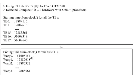
Figure 17: A code example to confirm the TB-level resource management on GPUs
To further confirm the TB-level resource management, we performed the following experiment on GTX680 (Kepler) GPUs with CUDA 5.5. The kernel code used in this experiment is shown in Figure 17. The grid dimension is set as 120 (i.e., 120 TBs) and the TB size is set as 1024 (i.e., 32 warps). The statement in line 4, ‘if(tid < 32)’ where ‘tid’ is the thread idx within a TB, forces the first 32 threads (or the first warp) in a TB to delay for an amount of time specified with the variable ‘clock_count’. The starting and ending times of all the threads are stored in global memory arrays. In this experiment, the variable ‘clock_count’ is set as (30 * deviceProp.clockRate) such that the execution time is always 30ms across different GPUs.
From the execution results shown in Figure 18a, we can see that the first 16TBs (TB0-TB15) are launched at similar times. The reason is that a GTX680 GPU has 8 SMXes and each SMX is capable of launching 64 warps (2 TBs) for our kernel. As shown in Figure 17, the first warp has the longest execution time among all the warps in each TB. In Figure 18b, we report the execution time of all the warps in TB0 as an example. From Figure 18, we can see that for each TB, although 31 warps finish execution much earlier than the warp0, a new TB cannot be launched until the warp0 has finished the execution. In other words, the GPU cannot dispatch a new TB to an SM/SMX unless all the warps from a previous TB have finished execution.
1. __global__ void TB_resource_kernel(…){ 2. ...
3. clock_t start_clock = clock();
4. if(tid < 32){ //tid is the threadid within a TB 5 clock_offset = 0;
6. while( clock_offset < clock_count ) { 7. clock_offset = clock() - start_clock; 8. }
9. }
10. clock_t end_clock = clock();
11. d_o[index] = start_clock; //index is the global thread id 12. d_e[index] = end_clock;