BOYETTE, WESLEY RYAN. Thrust and Specific Impulse Optimization of Eight-Centimeter Valveless Pulsejets at Low Subsonic Flight Speeds. (Under the direction of Dr. William L. Roberts).
by
Wesley Ryan Boyette
A thesis submitted to the Graduate Faculty of North Carolina State University
in partial fulfillment of the requirements for the Degree of
Master of Science
Aerospace Engineering
Raleigh, North Carolina 2008
APPROVED BY:
Dr. Andrey V. Kuznetsov Dr. Terry Scharton
Biography
The author was born Wesley Ryan Boyette on June 27,1980 in Hudson, North Carolina to Warren and Ruby Boyette. He was the youngest of three with two older sisters; Lara and Katie. At the age of nine, his family moved to Wendell, North Carolina where he stayed until graduating from East Wake High in 1998. He then attended the University of North Carolina at Chapel Hill for four years, obtaining a B.S. in Biology and a B.A. in Geography. In 2003, he enrolled full-time at North Carolina State University studying Aerospace Engineering and received his B.S. in 2006, graduating Magna Cum Laude. Immediately following graduation, he began his Master’s work under the direction of Dr. William Roberts.
Acknowledgements
Table of Contents
List of Figures ... vi
List of Tables...viii
1 Introduction... 1
1.1 Theory of Operation...1
1.2 History ...5
1.3 Related Work...6
1.4 Previous Research at AERL ...8
1.5 Objectives... 13
2 Experimental Apparatus...15
2.1 Pulsejet Designs... 15
2.1.1 Forward Facing ...15
2.1.2 Rearward ...18
2.1.3 Modified Rearward...19
2.1.4 Optimized ...22
2.1.5 Four Centimeter...23
2.1.6 Pertinent Design Dimensions and Ratios ...24
2.2 Air Delivery System ... 24
2.2.1 Cautionary Considerations ...27
2.2.2 Velometer ...27
2.3 Fuel Delivery System... 29
2.3.1 Flowmeters and Valves ...29
2.3.2 Fuel Injectors ...29
2.4 Spark Ignition... 32
2.4.1 Transformer and Switch ...32
2.4.2 Igniter...33
2.5 Electronic Balance ... 35
2.6 Load cell... 36
2.7 Thrust stand... 38
2.7.1 For Load Cell ...38
2.7.2 For Mass Balance...41
2.8 Heating apparatus... 42
2.9 Sound Level Meter... 44
2.10 Startup procedure... 44
3 Forward Facing Configuration...49
3.1 Evolution of a Methodology ... 49
3.1.1 Load Cell...49
3.1.2 Electronic Balance ...53
3.1.3 Final Apparatus...56
3.1.4 Difficulties and Considerations...58
3.3 Performance as a Function of Inlet Diameter... 80
3.4 Performance as a Function of Inlet Length... 82
3.5 Performance as a Function of Fuel Flow Rate... 87
3.6 Performance as a Function of Simulated Forward Velocity ... 90
4 Frequency and Temperature ...97
4.1 Measured Frequency... 97
4.2 Exit Temperature ...102
4.3 Analytical Frequency ...103
4.4 Frequency, Temperature and Performance...107
5 Hybrid Configurations ... 110
5.1 Thrust and Specific Impulse Results...111
5.2 Hybrid Configuration Trends...124
5.3 Case Study: Inlet 700081...127
6 Other Results ... 131
6.1 Operation on Hydrocarbon Fuels ...131
6.2 Sound Pressure Level...134
6.3 Comparisons with Computational Results ...134
6.4 “Optimized” Geometry...136
6.5 Experiments on 4 Centimeter Valveless Pulsejet...138
7 Conclusions ... 139
8 Future Work... 141
List of Figures
Figure 1-1: Humphrey cycle in p-V space ...2
Figure 1-2: Example of a valved pulsejet (Foa, 1960) ...3
Figure 1-3: Example of a valveless pulsejet (Foa, 1960) ...4
Figure 2-1: Side view of 8 cm pulsejet...16
Figure 2-2: 8 cm pulsejet and inlets ...18
Figure 2-3: Modified 8 cm pulsejet with 125 deg inlets and rearward injection ...21
Figure 2-4: 8 cm modified hybrid running on acetylene...21
Figure 2-5: Typical 8 cm pulsejet and "optimized" pulsejet ...22
Figure 2-6: 4 cm model along with 8 cm pulsejet and penny ...23
Figure 2-7: Control panel. (A) Power supply, (B) Ignition switch, (C) Air rotometer, (D) Hydrogen regulator valve, (E) Hydrogen stop valve ...26
Figure 2-8: Fuel injector with propane flames ...31
Figure 2-9: Fuel injector arrangement within combustion chamber ...31
Figure 2-10: Igniter while sparking...35
Figure 2-11: Electronic balance with 1.00 gram weight ...36
Figure 2-12: Omega DLC101-10 dynamic force sensor ...37
Figure 2-13: Drawing of vertical thrust stand designed for load cell...40
Figure 2-14: Final modified thrust stand with labeled components...42
Figure 3-1: Load cell voltage output during fuel cutoff...52
Figure 3-2: Mass versus time profile for typical run in early mass balance testing...54
Figure 3-3: Effects of obstruction location in pulsejet flowfield for inlet 700-125. (A) No obstruction, (B) Obstruction in inlet farfield, (C) Obstruction in inlet nearfield, (D) Obstruction in exhaust nearfield...58
Figure 3-4: Evidence of effects of clamping location. (A) Clamped behind combustion chamber, (B) Clamped at inlet ...59
Figure 3-5: Thrust data for inlet 300-125...63
Figure 3-6: Specific impulse data for inlet 300-125...64
Figure 3-7: Thrust data for inlet 415-125...65
Figure 3-8: Specific impulse data for inlet 415-125...66
Figure 3-9: Thrust data for inlet 550-125...67
Figure 3-10: Specific impulse data for inlet 550-125...68
Figure 3-11: Thrust data for inlet 700-125...70
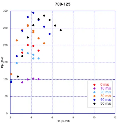
Figure 3-12: Specific impulse data for inlet 700-125...71
Figure 3-13: Thrust data for inlet 700-100...73
Figure 3-14: Specific impulse data for inlet 700-100...74
Figure 3-15: Thrust data for inlet 700-081...76
Figure 3-16: Specific impulse data for inlet 700-081...77
Figure 3-17: Thrust data for inlet 700-150...79
Figure 3-19: Thrust data for inlets of same area at 50 m/s...83
Figure 3-20: Thrust data for inlets of same area at 0 m/s...84
Figure 3-21: Maximum thrust and Isp for inlets of varying length...86
Figure 3-22: Peak thrust for each fuel flow rate...88
Figure 3-23: Peak specific impulse for each fuel flow rate...89
Figure 3-24: Forward flight speed at which peak thrust occurs by fuel flow rate ...93
Figure 3-25: Airspeed for which maximum Isp occurs as a function of inlet length...94
Figure 4-1: Frequency measurements for inlet 300-125 ...98
Figure 4-2: Frequency measurements for inlet 415-125 ...99
Figure 4-3: Frequency measurements for inlet 550-125 ...100
Figure 4-4: Frequency measurements for inlet 700-125 ...101
Figure 4-5: Temperature as a function of frequency...103
Figure 4-6: Percent error in frequency ...106
Figure 5-1: Thrust data for inlet 500-088 + 180 deg hybrid ...112
Figure 5-2: Specific impulse data for inlet 500-088 + 180 deg hybrid ...113
Figure 5-3: Thrust data for inlet 700-081 + 180 deg hybrid ...114
Figure 5-4: Specific impulse data for inlet 700-081 + 180 deg hybrid ...115
Figure 5-5: Hybrid configuration in "torch" mode...116
Figure 5-6: Thrust data for inlet 700-081 + 125 deg hybrid ...117
Figure 5-7: Specific impulse data for inlet 700-081 + 125 deg hybrid ...118
Figure 5-8: Thrust data for inlet 700-100 + 125 deg hybrid ...120
Figure 5-9: Specific impulse data for inlet 700-100 + 125 deg hybrid ...121
Figure 5-10: Thrust data for inlet 700-125 + 125 deg hybrid ...123
Figure 5-11: Specific impulse data for inlet 700-125 + 125 deg hybrid ...124
Figure 5-12: Thrust for all cases with inlet 700-081 at 50 m/s ...129
Figure 5-13: Specific impulse for all cases with inlet 700-081 at 50 m/s ...130
List of Tables
Table 2-1: Critical dimensions and ratios for pulsejet configurations ...24
Table 2-2: Required rotometer settings for simulated velocity...28
Table 3-1: Dimensions of inlets tested ...61
Table 4-1: Averaged analytical and measured frequencies...105
Table 4-2: Average performance characteristics for 4 inlets...107
Table 5-1: Peak results for hybrid configurations ...125
1
Introduction
The pulsejet is a member of a small group of thrust generators that are unsteady. The
mechanical simplicity of the pulsejet makes it relatively easy to construct and operate. On
the other hand, its unsteady nature and the competing governing principles of fluid
mechanics, acoustics, and chemical kinetics make analysis and prediction of pulsejet
behavior a very formidable task.
1.1
Theory of Operation
The pulsejet operates on the Humphrey cycle. A diagram of the Humphrey cycle is
given below in Figure 1-1. The cycle begins with 1-2, isentropic compression. This is
followed by 2-3, isochoric heat addition provided by combustion. The path 3-4 is the
isentropic expansion following combustion. The cycle is completed by 4-1, isobaric heat
rejection. The pulsejet is generally separated into three components: inlet, combustion
chamber, and exhaust. The inlet brings fresh air into the combustion chamber, which
initially contains hot combustion products at sub-atmospheric pressure. Fuel, which is
continually being released into the combustion chamber, then reacts with the fresh air and
combustion of the gasses creates a large pressure rise at essentially constant volume. The
pressure difference between the combustion chamber and the ambient pressure at the exhaust
exit then causes the hot products to expand down the exhaust tube being released into the
atmosphere. With the combustion chamber once again at sub-atmospheric pressure, the cycle
restarts. Initially a spark is required to initiate combustion but after a number of cycles, the
sufficient for autoignition. In many cases, the post-expansion pressure in the combustion
chamber is low enough for fresh reactants to be automatically pulled in through the inlet. As
a result, pulsejets can often run statically with only an external fuel source necessary to
maintain operation.
Figure 1-1: Humphrey cycle in p-V space
Pulsejets can be divided into two types: valved and valveless. Valved pulsejets
contain a series of valves separating the inlet from the combustion chamber. An example
diagram of one is given in Figure 1-2, with an enhanced view of the valves. These valves are
chamber cannot flow back into the inlet. Thus, the valves stay closed during the combustion
phase and most of the expansion phase. The exhaust duct acts as a tube open at one end so
once the pressure wave created by combustion reaches the exhaust plane, an expansion wave
is reflected and travels back to the combustion chamber, creating low pressure and reopening
the valves. Large pulsejets typically utilize valves for their superior performance but as the
size of the pulsejet is reduced, valves may become a liability and one may wish to consider
the valveless version.
Figure 1-2: Example of a valved pulsejet (Foa, 1960)
The primary difference between the valveless and valved pulsejets is, of course, the
absence of valves. In fact, the valveless pulsejet, shown in Figure 1-3, closely resembles a
ramjet. One of the primary differences between it and a ramjet, as far as construction, is the
abrupt increase in area from the inlet to combustion chamber. The absence of valves creates
the drawback of lower combustion chamber peak pressures since the building pressure now
has two escape routes. Furthermore, if gasses are allowed to exit through the inlet, they will
contribute negatively to the thrust. However, at small scales, the valves become inefficient.
difficult for combustion products to exit through the inlet. Some methods for doing so have
included turning the inlets around and including immobile obstructions at the
inlet-combustion chamber interface. Another challenge in valveless design is in scaling the
dimensions appropriately so that the acoustic characteristics of the pulsejet allow operation.
The valvless pulsejet essentially has two components with competing acoustics. The inlet
and the exhaust have their own characteristic frequencies and both provide the expansion
waves that are crucial to lowering combustion chamber pressure. If these frequencies are not
matched sufficiently, operation may not be possible.
Figure 1-3: Example of a valveless pulsejet (Foa, 1960)
As with any propulsion system, pulsejets have their pros and cons. Probably the
biggest advantage is the pulsejet’s simplicity. This makes it cost effective, expendable, low
maintenance, and easily scalable. For these reasons, it has been a popular choice for
hobbyists. Also, there is evidence that unsteady modes of combustion are actually capable of
higher cycle efficiency than any steady modes (Foa, 1960). And true constant volume
combustion yields better performance than the more common constant pressure combustion
(Brayton cycle). However, combustion in the pulsejet is not truly isochoric. Furthermore,
before combustion, which allows for much higher thermodynamic efficiencies. Also, the
pulsejet is confined to subsonic operation. For these reasons, the pulsejet’s practicality has
been confined to a relative few and rather specific uses, and will probably never be seen as a
good general-use propulsion system.
1.2
History
The concept of pulsating combustion is at least a couple of centuries old. By the turn
of the 20th century, two French engineers, Esnault and Peltrie, had designed a cyclical engine
that took advantage of pulsating combustion (Schoen, 2005). In 1909, Marconnet proposed
the “reacteur-pulsateur”, which according to Foa, was in every respect the precursor of the
pulsejet (1960). By the 1930’s, Paul Schmidt obtained a German patent for his Schmidt
tube. In the following decade, he along with a team from the company Argus, developed the
Argus-Schmidt tube which was responsible for propelling the German V-1 buzz-bomb,
which had a limiting velocity of 500 km/hr (Putnam, 1986). This would be the first and last
large-scale usage of pulsejets.
After WWII, the increasing efficiency of the turbojet made the pulsejet obsolete for
most applications. Project Squid was a collaborative effort between the US Navy and the Air
Force in the 1940s and 50s to further develop all types of jet propulsion, which led to some
research in valveless pulsejets (Schoen, 2005). At the same time, SNECMA began
developing versions of aerovalved pulse combustors (Putnam, 1986). Further research was
undertaken on valveless pulsejets in the 1960s by Lockwood and Hiller (Ordon, 2006). Since
relegated to the interests of hobbyists. This is an extremely brief overview of pulsejet
history. For more information, one should consult Putnam’s 1986 paper or the theses of
Schoen, Ordon, or McCauley, all of which are cited in the References section.
1.3
Related Work
Recently, advances in technology have made small, unmanned aerial vehicles a hot
research topic in the field of aeronautics. Smaller vehicles, of course, require smaller
propulsion units as well. The question then becomes how best to utilize chemical energy
through a micro-propulsive device. A few of the many options are rotary devices powered
by batteries, chemical rockets, gas turbine engines, and pulsejets. One of the objectives of
this research is to investigate the viability of pulsejets as a propulsion unit at very small
scales.
The problem with using a system that relies on batteries is that the highest energy
densities yet proven in batteries may still be an order of magnitude lower than energy
densities presented by hydrocarbon fuels. Chemical rockets are fundamentally limited to low
specific impulse relative to those of gas turbine engines and, at small scales, boundary layer
effects will only make this situation worse. The more interesting and more relevant issue is
how micro-gas turbine engines might compare to pulsejets at a similar scale.
The problems with microcombustion can essentially be grouped into three topics, as
outlined by Waitz (1998). The first obstacle is the residence time in the combustion zone.
Shorter length scales mean shorter residence times for similar mass flow rates. As the
becomes a challenge to complete the combustion process to an appreciable degree while the
reactants are still in the intended combustion chamber. The crucial parameter in this case is
the Damköhler number, which is the ratio of the residence time to the characteristic chemical
reaction time. The solution may to be increase residence time, which means increasing the
combustor size. According to Waitz, if a full-size engine is scaled down by a factor of 500,
then the volume of the combustor must grow relative to the engine by a factor of about 40 to
provide sufficient residence time. On the other hand, one may want to increase the chemical
kinetic time scale, which may be done by adding a catalytic surface. Unfortunately, this
poses problems because a sufficient amount of surface area must be provided and sufficient
time for diffusion of reactants to the catalytic surface becomes an equally important time
factor (Spadaccini, 2007). Along with these factors, one must also consider the time
necessary for sufficient reactant mixing.
The second obstacle is heat transfer losses. At low length scales, the surface area is
much larger relative to the volume of the combustor. The additional surface area increases
the convective heat loss from the hot combustion gases. At some critical size, the heat
transfer from the flame front may be enough to quench the reaction. This will have the effect
of reducing flammability limits and reducing the normally high combustor efficiencies of gas
turbine engines (Waitz, 1998).
A third obstacle is material properties. Compressors and turbines are composed of a
very large numbers of well-machined parts. These parts, in addition to being expensive to
machine, have temperature and pressure limits. The use of ceramics can mediate the effects
machining and use of such parts is possible but the complexities involved increase cost and
decrease robustness.
The valveless pulsejet generally exhibits lower specific impulse than a valved
pulsejet, which in turn has lower specific impulse than typical gas turbine engines. At the
length scales studied in this research, adding valves to the pulsejet is not feasible, at least not
in the petal valve configuration that is typically used. Certainly the valveless pulsejet is
easier to machine than the micro-gas turbine engine because of its lack of moving parts,
however, some of the same obstacles that exist with small gas turbine engines also exist with
small valveless pulsejets. In particular, fuel choices are going to be limited by the residence
time and heat transfer properties of the combustion chamber.
1.4
Previous Research at AERL
This research was conducted at the Applied Energy Research Laboratory at North
Carolina State University in Raleigh, North Carolina. AERL has been conducting pulsejet
research for several years now and I am only the most recent investigator. Much of this work
has been made possible by the work that has preceded mine. Furthermore, the results and
conclusions of the past have provided me with valuable guidance and knowledge not only
about pulsejet operation but also laboratory methods. Each of these experimental
investigators (all of whom were Master’s students) made crucial contributions to the body of
knowledge concerning pulsejets. I would be remiss if I did not report on their findings.
Michael Schoen was one of the first AERL pulsejet investigators and he received his
attempted operation using both hydrogen and propane, only hydrogen succeeded. It should
be mentioned that “success” in this case, as with all AERL research preceding mine, meant
continuous operation without forced air. The primary objective was to investigate the
consequences of varying inlet length, inlet diameter, tail pipe length, and tail pipe exit
geometry. His quantitative results include resolved chamber pressures and
time-resolved thrust. However, no net thrust was measured for these cases, as the thrust stand was
not sensitive enough for such low values. He found that one of the results of reducing inlet
area was a decrease in the maximum allowable fuel flow rate. However, he found no trend
associated with maximum fuel flow rate and inlet length suggesting boundary layer build up
did not have significant effect on air intake volume. Schoen also suggested that higher
operating frequencies allow higher fuel flow rates (Schoen, 2005). Ultimately, he laid the
groundwork for much of the valveless pulsejet work that was completed later.
Adam Kiker, also a graduate student, finished his research in December of 2005. His
work dealt with a valveless pulsejet that measured only 8 cm in length. The geometry of the
smaller pulsejet was directly scaled down from the 15 cm pulsejet except that the combustion
chamber was kept the same size. A version with forward facing inlet and a configuration
using 2 rearward inlets were designed such that the total cross-sectional inlet area was equal
for both. He attempted to use a Kistler load cell for thrust measurements but found it
difficult to use in obtaining average thrust, and suggests using a linear load cell with a long
rise time. Attempts to measure net thrust were largely unsuccessful. By measuring
combustion chamber pressure, he found that with the forward facing inlet, the operating
efficiently around 5 or 6 SLPM where peak pressure is highest. In testing the rearward
configuration, he actually found lower peak pressure in the combustion chamber and he
indicates that the range of fuel flow rate is in the 4 to 6 SLPM range. He also notes that a
reduction in exhaust diameter results in higher peak pressures. Kiker also attempted to
construct and operate a 5 cm valveless pulsejet. The jet was coated with a catalyst (platinum)
in order to speed up the chemical kinetics, but the author notes no apparent improvement
after having done so. Eventually, he was able to operate the 5 cm model without air in a
rearward configuration (Kiker, 2005). His work at the 8 cm scale is a direct predecessor to
the work presented here.
The next graduate student working on pulsejets was Rob Ordon who graduated in
2006. He modified a BMS valved pulsejet into a 50 cm valveless version with different
inlets. As with the previous students, he was unable to make net thrust measurements of the
valveless model using his thrust stand. This was the first valveless model to run successfully
on propane. It was found that as inlet diameter increased, more fuel was required to run the
jet. Longer extensions allowed a greater variety of inlets and lower fuel flow rates. His
results showed that frequency is a function of both exhaust length and inlet diameter in that
increasing diameter increases the frequency. Perhaps his most important contribution was in
showing that the inlet can be modeled as a Helmholtz resonator and the exhaust is similar to
a quarter wave tube but more like a 1/6th wave tube. For a Helmholtz resonator, one can
determine the frequency using the speed of sound, c, the inlet area, S, the inlet length, L, and
Similarly for the exhaust tube, where is the length of the exhaust;
Ordon then shows that the measured frequency is well predicted by averaging the calculated
frequencies of inlet and exhaust. He also did some testing of the valved hobby scale model,
which showed significantly higher combustion chamber pressures than in valveless models,
as expected (Ordon, 2006).
Finishing in 2006, Christian McCauley performed experiments on a wide range of
pulsejets including the BMS hobby scale, a 1 meter long engine with 25 pounds of thrust, and
a 25cm valveless model designed to work on heavy (liquid) fuels. His first achievement was
in successfully running the 25 cm jet on propane which required adding a flare to the exit,
adjusting the fuel injection system and including a warm-up period before cutting off air to
provide adequate heating of the combustion chamber. Then to run on heavier liquid fuels, he
discovered that the pulsejet must be started on propane then switched to the liquid fuel,
which ran through preheating coils. Through his efforts, he was eventually able to run the 25
cm valveless model without air assistance on both gasoline and kerosene. Interestingly, no
link was found between fuel choice and operating frequency; the frequency appears to be
determined by geometry alone. Furthermore, his results agreed with Ordon’s with respect to
predicting the jet’s frequency. One aspect of the jet’s operation that he paid particular
attention to was the type of fuel injector. He notes that the jet was highly sensitive to fuel !
f = c
2" S VL ! Lb !
injector location and saw that it would not operate if fuel was injected oriented against the
flow of air but operated most preferably oriented at 90 degress to the flow. Another
observation was that fewer and smaller holes in the fuel injector were preferable due to
improved mixing. McCauley was also able to investigate performance-enhancing methods
such as forward flow deflectors and flow rectifiers (McCauley, 2006).
The most recent pulsejet experimentalist prior to myself was Ranjith Kumar who
received his M.S. in 2007. Kumar did most of his work on the 50 cm valved pulsejet from
BMS. He was able to use a thrust plate as a means of indirect thrust measurement. His
thrust measurements were initially aimed at investigating the use of an augmenter. An
augmenter is a device which is little more than a large tube located downstream of the
pulsejet exit. It is able to enhance the thrust of the pulsejet by entraining extra air from
outside of the pulsejet into the exhaust, effectively increasing the momentum flux that
determines the thrust. By using an augmenter, he was able to achieve up to 1.5 times the
unaugmented thrust. Kumar also attempted to validate some of the computational work
performed by Tao Geng involving the effects of flares of varying area ratios on the exhaust
of the pulsejet. His findings showed that the nominal flare with an area ratio of 1.4 and no
curvature gave the best thrust performance. While these results did not agree with the
computational results, the study was an important step for the group in that it was the first
time experimental results were used to validate computational findings. He also did some
experimental work with a 1 meter valved pulsejet and a large Helmholtz resonator (Kumar,
Alongside the experimental research at NCSU, Tao Geng helped with computational
support and finished his PhD in 2007. Geng was able to investigate a number of different
phenomena regarding pulsejets. His first task was to look at the 15 cm valveless pulsejet that
Schoen was developing in the lab. He found that fresh air for the combustion cycle was
introduced through the inlet only. Configurations with multiple opposed facing inlets had
similar characteristics as the conventional forward facing versions. He also helped to explain
how shorter pulsejet lengths require shorter combustion time scales and, thus, faster fuels.
With the 8 cm model, his simulations matched the experimental results in operation
frequency and peak pressure. He also did some modeling of the valved 50 cm pulsejet, with
which he was able to investigate the importance of a flare at the exhaust exit that helps to
augment thrust by inducing starting vortices (Geng, 2007). The ability to perform
computational analysis side-by-side with experimental work has been tremendously
advantageous.
1.5
Objectives
The following study explores a variety of issues concerning an 8 cm valveless
pulsejet. The goal is to expand upon the extensive research that has already been performed
at the AERL. This research has two primary objectives. While the effects of inlet geometry
have been studied before, this is the first investigation to collect reliable net thrust
measurements on a valveless model. Therefore, the first objective is to use net thrust and
specific impulse to evaluate a number of different inlet geometries. Also, no previous
a second objective of this study is to study trends in thrust and specific impulse as a function
of forward flight speed.
In addition to these primary goals, several other smaller phenomena are investigated.
Frequency prediction based on a previously stated analytical model is performed with the
forward facing inlets and links between frequency, temperature, and performance are
confirmed. Alternative pulsejet configurations such as rearward facing and hybrid (rearward
plus forward facing) inlets are considered. An “optimized” geometry that has been suggested
through computational work is manufactured and tested briefly. Various fuels are tested and
compared at the 8 cm level for the first time. Also, a 4 cm valveless model that is directly
2
Experimental Apparatus
As mentioned, this research is a continuation of previous research at the AERL. For
this reason, much of the hardware and many of the practices have been developed by others
and handed down over the previous three years.
2.1
Pulsejet Designs
The vast majority of the work done on this project employed the use of an 8 cm
valveless pulsejet using a forward facing inlet. Testing was done with slight variations on the
base design. Each of these design permutations will be discussed in detail. All physical
models were machined out of 1-inch diameter steel or stainless steel by the Mechanical and
Aerospace Engineering Machine Shop.
2.1.1
Forward Facing
The dimensions for the forward facing inlet configuration were adopted from the
work of Adam Kiker who initially designed the engine by scaling down the 15 cm version
except keeping the combustion chamber the same size (Kiker, 2005). For this reason, the
combustion chamber on the 8 cm pulsejet comprises considerably more of the volume
fraction of the total engine than with other, larger designs. This gives it an odd “bulbous”
look as opposed to the fairly slender shape of the 15 and 25 cm variations. Because the
interior cannot be machined with an inlet, the main body includes only the combustion
chamber and the exhaust tube, and the combustion chamber’s interior is partially threaded to
allow for inlet attachment. This arrangement allows for the fitting of any number of different
given and the primary sections annotated. Table 2-1 lists the pertinent dimensions and ratios
of this model. Note that although dimensions here are given in centimeters (except where
threading is required) in order to keep consistent units throughout this document, the original
drawings were prepared and submitted to the Machine Shop in inches.
Figure 2-1: Side view of 8 cm pulsejet
The inlet base is designed to thread into the combustion chamber a length of 0.508
cm. Therefore, the combustion chamber is considered to occupy the volume beginning at the
inlet base and ending at the point where the area tapers down to the size of the exhaust tube.
igniter, which is a 10-32 screw (see section 2.4.2). The smaller hole is where the fuel
injector is inserted (see section 2.3.2).
The exhaust tube begins where the tapered section ends and extends to the exit face.
The version drawn here and tested is seen to have a flared exhaust. Many investigations of
pulsejets, both valved and valveless, by the AERL researchers and others have indicated that
a flared nozzle such as this is beneficial both for starting the pulsejet and for performance. In
fact, a flared nozzle is standard issue for hobby pulsejets. The area ratio used in this design is
around 2, which was taken roughly from computational results conducted by Tao Geng,
indicating this was near the optimal value (Geng, 2007).
Several models using this design were manufactured while this research was ongoing.
Some of the models had flared ends and others did not. Both types operated and no
noticeable difference was observed. No quantitative comparison between flared and unflared
designs was made as it was deemed outside of the scope of this project. All of the results
using a forward facing inlet reported here were made with the same model. This is for
several reasons. First, the initial set of models were made with slightly larger fuel injector
holes than necessary. This caused unnecessary leakage of exhaust gasses from the
combustion chamber, and was detrimental to the pulsejet’s performance. Second, although
these pulsejets are extremely simple devices, they too are subject to wear and tear with
extended usage. It is not known how significantly this affects performance but erosion of the
metal surface can be seen on both the interior and exterior and a slight curving of the exhaust
the final set of measurements reported here. Figure 2-2 is a view of this model along with
each of the inlets tested.
Figure 2-2: 8 cm pulsejet and inlets
2.1.2
Rearward
Most, if not all, of the jets from Kiker’s research remained at the lab. A couple of 8
cm pulsejets ready for rearward facing inlets were available. These jets were geometrically
similar to the forward facing configuration with only a few differences. Obviously, the big
difference is that the combustion chamber now includes two holes that allow for screws
oriented at 180 degrees with respect to the incoming airflow. The holes are on either side of
in all cases were 0.914 cm long with an individual area of 0.039 cm2. The exhaust tube is
0.254 cm longer than in the geometry detailed above. Finally, there is no flared nozzle on
this pulsejet. Rather, the exhaust tube is partially threaded to allow for extensions, although
in this research, these extensions were never used. The inlet end of the combustion chamber
may be plugged if one wishes to utilize the pulsejet in its rearward facing configuration.
Alternatively, a forward facing inlet may also be used to create a hybrid configuration,
utilizing both forward and rearward inlets, which has never been analyzed at AERL before.
2.1.3
Modified Rearward
The first original design constructed during this research is referred to as the modified
rearward configuration. It has the same internal geometry as the configurations discussed so
far and includes a flared nozzle. However, it differs from the previous discussions in two
important ways.
First, this geometry has two holes in the combustion chamber that can accommodate
slightly rearward facing inlets. The holes are threaded to fit 8-32 screws and are placed on
either side of the exhaust tube. These holes are still located on the converging section of the
combustion chamber but are located slightly closer to the chamber’s straight section. Instead
of being oriented at 180 degrees to the flow, they are oriented at 125 degrees.
The other difference is that the configuration is actually constructed of three parts.
The combustion chamber is separate from the exhaust tube and is tapped beyond the tapered
section to allow the exhaust tube to thread into it. The exhaust tube is then threaded at the
end but is straight along the exterior. Along the exterior, however, a groove has been
machined that is just wide and deep enough to accommodate the fuel injector. The third
component is a sleeve that fits over the fuel injector and exhaust tube and threads onto the
exhaust tube’s exterior at the combustion chamber end. The reasons for constructing this
configuration are twofold. First, the exhaust is generally the hottest part of the pulsejet and is
thus an ideal location for regenerative heating of the fuel. By running the fuel injector along
the exhaust and having it in direct contact with this metal, this configuration offers the
possibility of heating the fuel with no external heat addition source and no cumbersome
tubing wrapped around the jet’s exterior. Furthermore, it was already mentioned that having
an inadequate seal between the fuel injector and combustion chamber may result in a loss of
peak pressure, and thus overall performance. By getting rid of the hole in the wall of the
chamber, any leakage along the fuel injector will now escape in the same direction as the
exhaust gasses and should only contribute to the momentum in the desired direction.
As with the other configurations, the combustion chamber’s straight section is
threaded to allow for a plug or any number of forward facing inlets. A cross-sectional
drawing of the separate components is shown in Figure 2-3. One version of the hybrid
modified is shown in Figure 2-4 while running on acetylene, as proven by the characteristic
white flames. This striking picture was taken in the dark for dramatic emphasis of the use of
three inlets and one exhaust. It is also interesting to note the clear delineation between the
combustion chamber piece (glowing red) and the outer sleeve between the chamber and the
Figure 2-3: Modified 8 cm pulsejet with 125 deg inlets and rearward injection
2.1.4
Optimized
For the first time in the history of pulsejet research at AERL, computational results
were used to assist in the development of an entirely new geometry. Fei Zhang developed a
MATLAB code which, when given a total length and inlet length, will output an “optimized”
geometry for the pulsejet. Based on the MATLAB results for a test case using an 8 cm long
pulsejet at static conditions, a pulsejet was designed and manufactured in order to test the
optimization code. The dimensions are given in Table 2-1. It is referred to as the “optimal”
configuration. Two notable changes resulting from the optimization are the decrease in
combustion chamber volume and the increase in exhaust tube area. This results in a
reduction in chamber area to exhaust area ratio by a factor of almost 9. Other than a radically
different internal geometry, one major difference between the “optimized” geometry and
previous configurations is that the exterior required no extra machining, but, as a result, gave
this model much thicker walls along the exhaust tube. Its shape gives it a very distinctive
look. The machined model is shown in Figure 2-5 alongside a typical pulsejet for
comparison.
2.1.5
Four Centimeter
In addition to the extensive work conducted at the 8 cm level, some qualitative work
was also done on a 4 cm model. This model was directly scaled down from the existing 8 cm
models with all interior linear dimensions being cut in half. The walls were left relatively
thicker due to the inherent difficulties in machining such small models. The initial design
called for a fuel injector hole to be made on the converging section of the combustion
chamber to allow for an injector with the same diameter as those used on the 8 cm models.
This version can be seen in Figure 2-6 where an 8 cm pulsejet and a penny are shown for size
comparison. However, a later design used a smaller fuel injector hole to be placed on the
straight section of the combustion chamber, as was done with the 8 cm model. Likewise, this
model included a flared exhaust and allowed for different inlets.
2.1.6
Pertinent Design Dimensions and Ratios
Table 2-1 gives all of the crucial dimensions and ratios for each design. It is
important to realize that these dimensions play a critical role in determining the pulsejet’s
operating characteristics. Even seemingly slight changes in such design parameters can have
dramatic effects on performance, including rendering the pulsejet inoperable.
Table 2-1: Critical dimensions and ratios for pulsejet configurations
Parameter 8 cm Forward Facing 8 cm 180deg Rearward 8 cm 125deg Modified Rearward 8 cm "Optimized" 4 cm Forward Facing
CC diameter (cm) 1.905 1.905 1.905 0.750 0.953
CC area (cm2) 2.850 2.850 2.850 0.442 0.713
CC length (cm) 1.694 1.694 1.694 1.600 0.843
CC volume (cm3) 3.164 3.164 3.164 0.601 0.395
Exhaust diameter (cm) 0.445 0.445 0.445 0.500 0.224
Exhaust area (cm2) 0.156 0.156 0.156 0.196 0.039
Exhaust length (cm) 4.826 5.080 5.080 5.000 2.540
Flare area (cm2) 0.304 0.156 0.317 0.392 0.073
Flare area/Exhaust
area 1.95 1.00 2.04 2.00 1.85
CC area/Exhaust area 18.33 18.33 18.33 2.25 18.10
2.2
Air Delivery System
All of the pulsejets that have been used at this facility require a forced injection of air
in order to begin operation. Prior to this investigation, however, the air was only used in
starting the pulsejet and, if at all possible, was removed from the pulsejet’s inlet as soon as
independent operation was possible. For the present research, the air was not only necessary
for starting the pulsejet, but it was also used to simulate forward flight speeds in lieu of a
wind tunnel. For this reason, the air delivery system was a crucial component of my testing
At the AERL, there is an Ingersoll-Rand UP6-15CTAS-150 air compressor unit. This
unit has a small tank, which can be pumped up to about 900 kPa (9 atm). This unit is then
connected to a much larger tank which, when connected through a valve, is allowed to store
air at the same pressure. This tank is then connected through a series of hoses to a regulator
valve. By manipulating this valve, the user is able to control the amount of airflow passing
through the line. The line is connected to an Omega variable-area rotometer capable of
measuring up to 39 SLPM of air. In reality, however, one can go as high as 41 SLPM by
allowing the center of the ball to rest between the “AIR” mark and the Omega symbol at the
top of the glass portion. This rotometer was positioned on a control panel that was thankfully
constructed before this research began and located next to the optical table where the
majority of the experiments were conducted. Shown in Figure 2-7, it contains components of
Figure 2-7: Control panel. (A) Power supply, (B) Ignition switch, (C) Air rotometer, (D) Hydrogen regulator valve, (E) Hydrogen stop valve
Having passed through the rotometer, the air is then allowed to travel through a line
The exit of this stainless steel section forms the nozzle that is directed at the inlet face of the
pulsejet during operation. This nozzle blasting air at the inlet can then be used as a simulated
wind tunnel if the air speed is known at the inlet face.
2.2.1
Cautionary Considerations
It is very likely that the air exiting the nozzle exhibits pressures above atmospheric in
the near field. Some distance may be required in order for this air to expand to ambient
pressure. If the nozzle is too close to the inlet, the increased pressure may artificially
enhance the pulsejet’s performance, yielding unrealistic results. In order to prevent this as
much as possible, the nozzle exit should be placed as far as possible from the inlet face.
Furthermore, the air exits the nozzle with a parabolic velocity profile and quickly transitions
to turbulence. On the other hand, the inner diameter of the air nozzle is about 0.444 cm,
which is sufficiently larger than most of the inlet diameters, indicating that the entire inlet
face should see the same incoming velocity.
For these reasons, this method can only be considered a rough approximation to wind
tunnel conditions, which in turn is an approximation to actual flight conditions. This should
be kept in mind when considering the results presented herein. Of course, this discussion
does not apply to any results for static cases as the air nozzle plays no role in the experiment
once the pulsejet has started and is running independent of forced air.
2.2.2
Velometer
In order to measure the air speed at any location away from the air nozzle exit, an
HVAC systems, this equipment was useful in estimating airflow rates for this purpose. It
used one of two pitot probes (each with a different sensitivity) to measure up to 10000 feet
per minute, which corresponds to about 50 meters per second. As it turned out, 50 m/s was
the target velocity, and by placing the probe directly in the path of the air exiting from the
nozzle, it was possible to match a velocity with a volume flow rate for a given distance
between the probe and nozzle exit.
As mentioned above, it was deemed advantageous to have the nozzle as far from the
inlet face as possible. Thus, the goal was to find the maximum distance that the nozzle could
be placed away from the inlet face while still achieving 50 m/s airspeed at the inlet. Since
the air rotometer could not exceed 41 SLPM, the distance was found that corresponded to 41
SLPM and 50 m/s. This distance was measured as 2.95 cm. Using the velometer, Table 2-2
was then constructed, finding the corresponding volume flow rate for a given airspeed for a
distance of 2.95 cm. These airflow settings were used in all of the experiments and great
care was taken to ensure that the distance between the air nozzle and inlet face was kept at
this distance for all cases.
Table 2-2: Required rotometer settings for simulated velocity
Airspeed (m/s)
Rotometer reading (SLPM)
0 0
10 12.5
20 21.0
30 28.5
40 35.0
2.3
Fuel Delivery System
All of the fuels used in the experiments discussed here were delivered to the pulsejet
in gaseous form. These fuels (with one minor exception) were all stored in large containers
provided by National Welders Supply. The fuel of choice, as in past research on small
pulsejets, was hydrogen, and to a lesser extent, acetylene and propane.
2.3.1
Flowmeters and Valves
Fuel flow rates were regulated using two flowmeters. Each flowmeter was a Hastings
Mass Flowmeter Model 200H. A Hastings Instruments Power Supply Model 40 was
connected to both flowmeters and provided a digital readout of the volumetric fuel flow
rates. The user interface of the power supply can be seen on the control panel in Figure 2-7
as well as the regulator valves for the hydrogen supply line. Hydrogen was monitored on
Channel 4 while acetylene and propane were monitored on Channel 1. The regulator valves
for acetylene and propane were not part of the control panel but were instead attached to the
nearby optical table. The hydrogen was controlled through a Swagelok SS-31RS4 metering
valve that allows up to 12.7 SLPM with a pressure drop of 10 atm. However, expecting
lower fuel flow rates than with hydrogen, the acetylene and propane were controlled by way
of a SS-SS4 metering valve that only allows 1.1 SLPM at 10 atm.
2.3.2
Fuel Injectors
Once the fuel leaves the flowmeter, it is transported through quarter-inch plastic
tubing to a section of quarter-inch stainless steel tubing which leads to a fuel injector. The
Kiker’s work. The injector itself is made from hypodermic tubing available from SmallParts,
Inc. The tubing has 0.058-inch outer diameter and 0.042-inch inner diameter. The outer
diameter is large enough to fit snuggly in 1/16 inch tubing, so a 1/4 inch to 1/16 inch adapter
is all that is needed to fashion a fuel injector with a size appropriate for the 8 cm pulsejet.
Twelve-inch sections of the tubing were purchased and then each section could be split into
four 3-inch pieces.
The next step was drilling holes into the tubing. Once again, the Machine Shop was
helpful doing so. Two holes measuring 0.020 inches in diameter were drilled through both
sides of the tubing. The holes can be oriented in any number of ways and a few different
orientations were tried. McCauley found that fuel injectors with the holes oriented
perpendicular to the incoming airflow seemed to work best (McCauley, 2006). This
arrangement also seemed to work best for the 8 cm pulsejet although no quantitative data was
taken to support this claim. With a couple of exceptions, all of the data presented here was
taken with the injector shown in Figure 2-8 which features two holes, both oriented at 90
degrees to the flow, with diameters of 0.020 inches and with a distance of 0.080 inches
separating them. This injector is shown with propane flames emanating from its holes to
easily illustrate how they are oriented. The wide base of the flame gives an idea of how far
apart the holes are. Furthermore, the holes were placed along the tube such that they would
be in the center of the combustion chamber once the closed end of the tube reached the far
side of the chamber wall. This arrangement is diagrammed in Figure 2-9. As for closing one
then be grinded down slightly in order to fit through the pulsejet’s hole. This resulted in
some leakage through the closed end but not any significant amount.
Figure 2-8: Fuel injector with propane flames
The exceptions to this rule are the modified rearward configuration and the injector
used for the 4 cm model. The modified rearward configuration calls for the same size tube,
but in this case the tube must curve slightly once it is in the combustion chamber in order to
reach the center. As a consequence of this orientation, two sets of orthogonal holes were
placed near the closed end of this injector. For the 4 cm model, a similar orientation as above
was used but the injector itself was fashioned from tubing with an outside diameter of 0.036
inches and was placed inside the tubing used on the 8 cm models. An exposed portion of this
tubing was then inserted into the 4 cm pulsejet.
2.4
Spark Ignition
In addition to a fuel source and an air source, a pulsejet needs an ignition source in
order to start. It may be possible to preheat the pulsejet body to autoignition temperatures
and start the engine that way, but a spark most easily provides the ignition source. Once the
pulsejet has warmed up sufficiently, the spark is no longer needed. For the small and
thin-walled 8 cm pulsejets running on energetic fuels such as hydrogen, the spark was usually
only needed for a couple seconds if the air and fuel settings were appropriate.
2.4.1
Transformer and Switch
Because spark plugs generally require very high voltages to be fired properly, a
simple connection to a traditional outlet at 120 V is not sufficient. For this reason, a
transformer is necessary to step-up the voltage by stepping-down the current. Originally, a
Franceformer interchangeable ignition transformer was used for this purpose. This
replaced by a Pan-Tech Enterprises, Inc. model number HX-001 transformer that was
capable of 12 kV. Power from the transformer to the “hot” wire was controlled with an
ignition switch, which can be seen on the control panel in Figure 2-7. Once the pulsejet was
running well, the switch was turned off.
2.4.2
Igniter
Unfortunately with the 8 cm pulsejets, the option of using an off-the-shelf spark plug
is not available due to size constraints. For this reason, an ignition source must be fashioned
by the experimenter. Adam Kiker had, of course, tackled this problem before and his
solution was to use a copper wire inserted into a ceramic tube. The ceramic tube could then
be inserted into a metal screw that could then thread into the pulsejet’s combustion chamber.
With the “hot” wire attached to the copper wire and energized, a spark would form between
the end of the wire inside the pulsejet and the walls of the pulsejet, which was grounded. The
spark inside the combustion chamber would then be responsible for igniting the gaseous
mixture.
This method was essentially adopted for this research with some modifications. The
problem with sparking off of the combustion chamber wall was that the position of the
igniter had to be just right. Many times, this required constant readjustment of the igniter
itself and required a great deal of patience for what was seemingly one of the most trivial
aspects of the pulsejet. Furthermore, it was not uncommon for the ceramic insert itself to be
pushed out by the building pressure while running which would immediately terminate the
The solution was to use two separate copper wires; one to connect to the “hot” lead
and one to be grounded. With this set-up, the spark would form between the two wires
instead of between a wire and the wall. Ceramic tubes that are designed for thermocouples
can be purchased from Omega. The ideal tubes are 1/8-inch thick with two holes running
lengthwise through them. These holes are just large enough to fit 22 guage copper wire
through them and the fit is tight enough so that the wires do not slip easily out of position.
The wires were positioned so that a short portion (no more than 0.1 inches) of each wire
slipped out the end that would be placed in the combustion chamber. The spark would then
form at this location. Out the other end, enough wire was left for easy attachment of alligator
clips. The trick was to crack the ceramic piece such that one wire would exit the top at a
different location than the other and then the two wires were bent away from each other.
This was done to prevent the spark from occurring at the exposed end of the igniter as
opposed to the end inside the pulsejet. The ceramic piece could then be fitted into a 10-32
screw, which would then be screwed into the hole tapped in the chamber. This arrangement
is shown in Figure 2-10 with the ground wire on the left, the “hot” wire on the right, and a
spark forming between the two wires. It was also important that the ceramic piece just barely
fit inside the screw. There may be an adhesive that works even under the extreme
temperatures encountered with pulsejet operation but high temperature silicon was
ineffective. Nonetheless, if the ceramic could stay put in the screw, this arrangement formed
a very sturdy and reliable igniter. A similar but smaller arrangement was eventually used to
Figure 2-10: Igniter while sparking
2.5
Electronic Balance
For making measurements of mass, an Ohaus GT2100 electronic balance was
utilized. This balance has an easily readable digital display that reports mass to the
hundredth of a gram. To determine if the balance was accurate, a series of standard masses
were tested. Masses of 5 g, 1 g, 0.5 g, 0.1 g, 0.05 g, and 0.01g were all tested. The results
for the tests were remarkable. In all cases, the balance was accurate to within 0.01 g. For the
lighter masses especially, the balance often underreported the actual mass by 0.01 g. What
was interesting was that in almost every case where the mass was underreported while the
0.00 g. The balance can be seen in Figure 2-11 with the 1 g brass weight placed on the center
of the balance’s plate.
Figure 2-11: Electronic balance with 1.00 gram weight
2.6
Load cell
As with many of the previous investigations, an attempt to obtain time-resolved thrust
data in addition to net thrust data was made. To this end, it was decided to purchase a new
dynamic load cell. The Omega DLC101-10 dynamic force sensor, pictured in Figure 2-12,
was chosen for the job. For this particular force sensor, a force applied to the upper plate
produces an electrostatic charge that is converted instantly to voltage. This voltage output is
what indicates the dynamic force on the sensor.
Figure 2-12: Omega DLC101-10 dynamic force sensor
It is important to realize that the sensor is setup to operate at a zero bias condition
meaning that the time-averaged voltage will always tend to zero volts. Once a load is applied
and the force sensor is powered, the discharge time constant determines the amount of time it
takes for the voltage to settle to zero. For this particular sensor, the time constant was
reported as 50 seconds. This presents a problem if one is trying to measure the net force on
the sensor. Nevertheless, measuring time-resolved thrust is relatively straight forward if one
instance, if one sees a voltage output of 5.75 mV, this would correspond to a force of about
50 mN. The other important parameters to keep in mind are that the sensor had a high
frequency of 25kHz and a maximum load of 10 lbf, which are both far beyond the expected
range of the 8 cm pulsejets.
In addition to the load cell, a few other components were necessary to produce
results. An Omega ACC-PSI Power Supply supplied power to the sensor. The output could
be sent to an oscilloscope if the user simply wanted to monitor the data visually.
Alternatively, the output could be sent to a LabView program on a nearby computer. This
program was set up to record the signal and produce an FFT instantaneously. Previous
researchers had used the same program to record instantaneous thrust and pressure data.
2.7
Thrust stand
Equally as important as the method of measurement is the structural apparatus in
thrust measurements. Previous AERL researchers had tried a couple of different thrust stand
configurations but none had been able to get credible net thrust measurements. Producing
reliable thrust data was the most important objective of the research presented here and
knowledge of past attempts was helpful.
2.7.1
For Load Cell
The Omega dynamic force sensor’s design naturally suggests a vertical arrangement.
Previous tests of valveless pulsejets, as described, revealed just how small the thrust could be
so any horizontal design would need to be virtually frictionless. Ball bearings were
good option but the setup becomes complicated and probably expensive. Instead, the idea of
setting up the apparatus vertically seemed much more practical. There is no apparent reason
why a valveless pulsejet would behave differently depending on its orientation with respect
to Earth. Furthermore, there are no friction considerations if the thrust stand simply sits atop
the load cell.
Other considerations were necessary though. The load cell is sensitive to temperature
changes so the pulsejet could not be arranged with the exhaust facing down and blowing onto
the load cell. But if the exhaust points upward, the inlet of course faces downward and room
must be left between the inlet and the bottom of the thrust stand in order for the pulsejet to
breathe. Finally, the thrust stand also needed to be lightweight and rigid to give it a very high
natural frequency; one that would not interfere with the signal produced by the pulsejet cycle.
With the help of Dr. Roberts and an undergraduate student, the final design of a thrust
stand emerged and the designs were sent to the Machine Shop to be manufactured out of
aluminum. The design can be seen in Figure 2-13. The pulsejet connects to the upper plate
and the lower plate connects directly to the force sensor via a 1/4-28 set screw. The two
plates are then separated by three aluminum rods, which are tapped for 10-24 screws at each
end in order to attach them securely to the plates. The rods were cut at 3 inches each which
fortunately left just enough room to include the air nozzle at a distance of 2.95 cm from the
inlet face as noted above. The initial design required the upper plate to have a center hole
that was threaded to allow the inlet (which would also be threaded) to screw into the plate. A
second version allowed the inlet to slide through the center hole while another hole offset
Figure 2-13: Drawing of vertical thrust stand designed for load cell
The main difficulty with this setup is figuring out how to deliver fuel to the pulsejet.
As described above, the pulsejet is manufactured to have a fuel injector inserted into the
combustion chamber. This external force on the pulsejet could have a profound artificial
effect on any force measurements if one did not correctly account for it. One option was to
let the injector hang loosely onto the pulsejet so that the injector itself would hopefully move
with the pulsejet as it operated. Another option was to eliminate the external force of the
injector by widening the inlet slightly and bringing the injector up through the inlet. Both
2.7.2
For Mass Balance
Attempts were also made to use the mass balance to measure thrust. Once the idea of
running the pulsejet vertically was accepted, using the balance seemed like an obvious
solution. The electronic balance had at least two advantages. First, it was very accurate.
Second, the pulsejet frequency is so high that the balance would only be able to read net
thrust. As with the load cell setup, the question again is how to account for the fuel injector
and the fuel line leading from it to the flowmeter. Two attempts were made at measuring the
thrust in this way. In the first attempt, the fuel injector was positioned parallel to the hole in
the pulsejet with the hope that there was enough room for movement built into the setup to
allow for any movement associated with thrust.
In the second attempt, a modified thrust stand was assembled that attempted to fix the
position of the fuel injector so that any forces between the injector and the pulsejet would
only create internal forces, in that they would have no effect on the force measured by the
electronic balance. Figure 2-14 is a labeled picture of this modified thrust stand. Here, the
original thrust stand has been attached to a large aluminum base plate. Also attached to this
plate is a vertical bar that uses an aluminum-clamping device to hold the fuel injector in
place. The only external force, other than the forced air and the thrust of the pulsejet, is the
force created by the fuel line. There is no way to eliminate all external forces. Rather, the
working theory behind this attempt is that the force created by the fuel line on the fuel
on the pulsejet. As shown, a 90 degree elbow is used to allow the fuel line hang straight
down without touching the base plate or the table on which the balance is sitting.
Figure 2-14: Final modified thrust stand with labeled components
2.8
Heating apparatus
Another objective with this research was to test different fuels on the 8 cm model. As
previous researchers have discovered, running the valveless pulsejet on fuels other than
hydrogen is not a trivial task. One of the successful methods for running the pulsejets on
hydrocarbon fuels has been preheating the pulsejet and/or the fuel itself. For this reason,