Study of Buckling Behaviour of Beam and
Column Subjected To Axial Loading for
Various Rolled I Sections
Rekha Bhoi
1, L. G. Kalurkar
2P. G. Student, Department of Civ il Engineering, Jawaharlal Nehru Eng ineering College, Aurangabad, Maharashtra,
India1
Associate Professor, Depart ment of Civil Engineering, Ja waharla l Nehru Engineering Co llege, Aurangabad,
Maharashtra, India2
ABSTRACT: In this paper the buckling behaviour of an I - bea m under a xial load on column and beam is e xa mined.
Buckling loads are critica l loads where certain types of structure become unstable. The results of an e xtensive parametric study are presented in graphical form and summarized by simple design curves and ev aluating the effect of critica l buckling load for various symmetrical ro lled I - sections like Indian Standard Junior Bea m (ISJB), Indian Standard Light Weight Bea m (ISLB), Indian Standard Mediu m Weight Bea m (ISM B), Ind ian Standard Wide Flange Bea m (ISW B), Indian Standard Heavy Weight Beam (ISHB) for diffe rent depth are calculated by using software Ansys. The results of critica l buckling load calculated using Ansys are compared with the conventional method of Eu ler Buckling theory analytically.
KEYWORDS:Eu ler Buc kling, Fin ite Ele ment Analysis, Bea ms, Colu mns , A xial Loading, Critica l Buckling Load.
I.INTRO DUC TIO N
Buckling is a phenomenon which occurs in structures which are stiff in the loaded direction and slender in another direction. Initia lly equilibriu m is stable but when the load is increased there is a sudden increase in deflection in loading direction due to a displace ment in the slender direction. Th is is at the location of the bifurcation point. For structural behaviour this is a very important point because it is for slender constructions often governing and the plastic or e lastic cross-sectional capacity is not reached. When buckling does not occur at a certain load level, a structure is considered stable.
The commonly used hot rolled and built up steel co mpression me mbers, due to small th ickness of the constituting ele ments, are prone to e xcessive fle xu ral deformat ion and may fa il by fle xura l buckling. So metimes a type of buckling
are called Local Buck ling [1] characterised by wrinkling at isolated locations occurs wherein some thin portions of the
cross section of a me mber buckle locally in co mpression before other modes of buckling can occur. In such a situation, the cross section is no longer effect ive and the me mber may fa il. As a typical e xa mple , thin flange and web e le ments of an I - shaped cross section may individually buckle loca lly resulting in failure of colu mn.
Finite Ele me nt Me thod: - Finite e le ment method (FEM ) has a powerful tool for the nu merical solution of a wide
range of engineering proble ms. In this method of analysis, a comp le x region defining a continuum is descretized into simp le geo metric shapes called fin ite e le ment. The mat erial properties and the governing re lationship are considered over these elements and expressed in terms of unknown values at element corners. An assembly process duly considering the loading and constraints result in a set of equations. Solution of these equations gives us the approximate behavior of the continuum.
Euler B uckling anal ysis :
Pcr =
22
L
K
I
E
(1)
Where, I = Mo ment of inertia about axis of buckling.
K = Effective length factor based on end boundary condition of co mpression me mbers . E = Modulus of elasticity.
L = Length of me mber
II.B EHAVIOROFCOMPRESS IONMEMB ERS
The susceptibility of compression me mber to loca l buckling is usually governed by width to thickness ratios of the parts of the cross sections; hence, can be prevented by providing suitable width to thickness ratios for the ele ment parts of the cross – sections [4]. On the other hand, when an a xially loaded co mpression me mbe r beco mes unstable in its entirety, it is called overall instability [19]. In addition to local buckling, there are three genera l modes of fa ilure of a xia lly loaded steel me mbers, na me ly fle xura l buckling, torsional buckling and fle xura l torsional buckling, as well as for overa ll buckling; general modes of failure of a xially loaded steel me mbe rs are na me ly latera l buckling and latera lly torsion buckling. These buckling modes may be defined as follows:
1. Fle xu ral buckling: - Fle xu ral buckling is also called Euler Buckling. It is the primary type of buckling wherein me mbe rs subjected to bending or fle xura l action became unstable due to deflectio n about the axis having smallest radius of gyration, i.e . largest slenderness ratio.
2. Torsional Buckling: - Torsional buckling consists in fa ilu re of co mpression me mber of certain
configuration twisting or torsion about the longitudinal of the member. This type of buckling may occur when the torsional rig idity of me mber significantly s maller than its fle xu ra l rigidity. Th in wa lled me mbe rs with open cross sections are particularly susceptible to torsional buckling. The possibility of occurrence of the comple x buckling can be significantly reduced by providing sufficient end supports and intermediate lateral restraints [18].
3. Fle xu ral Torsional Buckling: - It consists in failure of co mpression me mbers of certain configuration by a
combination o f fle xura l buckling and torsional buckling due to simu ltaneous bending and twisting of the section. This type of buckling may occur in the me mbe rs having unsymmet rica l cross section including those with one a xis of symmet ry such as channels, structural tees, double angles a nd those without any axis of symmetry and unequal legs single angle sections.
4. Latera l Buckling : - The lateral buckling involves three kinds of deformat ion, name ly, latera l bending,
twisting and warping; it is feasible to think of various types of end conditions. But the supports should either co mpletely prevent or offe r no resistance to each type of deformation. Solutions for partia l restraint conditions are complicated [15].
5. Latera lly Torsional Buckling:-When the in -plane co mpressive load act ing on a plate is increased gradually,
III.PROB LEMS TATEMENT
In this study, cantilever beam (I-section) is selected. Analysis of various I sections (i.e. ISJB, ISLB, ISMB, ISWB, ISHB) was carried out in ANSYS. A ll the sections were run for spans of 1m in ANSYS as well as the results for Pcr were obtained by Ansys as well as conventional method that are Eule r Buckling Formula in spreadsheet.
IV.RESULT AND DISCUSSION
After analysing cantilever I - steel co lu mn and beam, c rit ical buckling load using ansys of various I sections like Indian standard junior bea m, long beam, med iu m bea m, wide flange beam and heavy weight bea m. Also comparat ive study of critica l buckling load using ANSYS software and Eu ler buckling formu la has done. Para metric curve of all colu mn and beam is as shown below:
Graph 1. Critical Load Of Column & Beam For ISJB And ISLB
Graph 2. Critical Load Of Column & Beam For ISMB And ISWB
0 20000 40000 60000 80000 100000 120000 ISJB 150 ISJB 175 ISJB 200 ISJB 225
Critical Load of column & Beam
Critical Load of column & Beam 0 200000 400000 600000 800000 1000000 1200000 ISLB 75 ISLB 125 ISLB 175 ISLB 225 ISLB 275 ISLB 325 ISLB 400 ISLB 500 ISLB 600
Critical Load of column & Beam
Critical Load of column & Beam
0 500000 1000000 1500000 2000000 2500000 IS M B 1 0 0 IS M B 1 2 5 IS M B 15 0 IS M B 1 7 5 IS M B 20 0 IS M B 2 2 5 IS M B 2 5 0 IS M B 3 0 0 IS M B 3 5 0 IS M B 4 0 0 IS M B 4 5 0 IS M B 50 0 IS M B 5 5 0 IS M B 60 0
Critical Load of column & Beam
Critical Load of column & Beam 0 500000 1000000 1500000 2000000 2500000 IS WB 1 5 0 IS WB 1 7 5 IS WB 2 0 0 IS WB 2 2 5 IS WB 2 5 0 IS WB 3 0 0 IS W B 3 5 0 IS W B 4 0 0 IS W B 4 5 0 IS WB 5 0 0 IS WB 5 5 0 IS WB 6 0 0
Critical Load of column & Beam
Graph 3.Critical Load Of Column & Beam For ISHB
Graph 4. Comparison Of Critical Load Using Ansys And Euler Buckling Formula For ISJB And ISLB
Graph 5. Comparison Of Critical Load Using Ansys And Euler Buckling Formula For ISMB And ISWB
0 200000 400000 600000 800000 1000000 1200000 1400000 1600000
ISHB 150
ISHB 200
ISHB 225
ISHB 250
ISHB 300
ISHB 350
ISHB 400
ISHB 450
Critical Load of column & Beam
Critical Load of column & Beam
0 20000 40000 60000 80000 100000 120000
ISJB 150 ISJB 175 ISJB 200 ISJB 225
Pcr by Euler Buckling formula
Pcr by Ansys
0 200000 400000 600000 800000 1000000 1200000
ISLB 75
ISLB 125
ISLB 175
ISLB 225
ISLB 275
ISLB 325
ISLB 400
ISLB 500
ISLB 600
Pcr by Euler Buckling formula
Pcr by Ansys
0 500000 1000000 1500000 2000000 2500000
ISMB 100
ISMB 150
ISMB 200
ISMB 250
ISMB 350
ISMB 450
ISMB 550
Pcr by Euler Buckling formula
Pcr by Ansys
0 500000 1000000 1500000 2000000 2500000 3000000 3500000 4000000
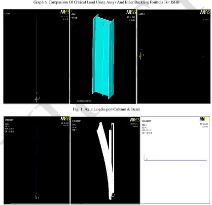
Graph 6. Comparison Of Critical Load Using Ansys And Euler Buckling Formula For ISHB
Fig. 1. Axial Loading on Column & Beam
Fig. 2. Buckling Mode Shape Of Column And Beam
0 200000 400000 600000 800000 1000000 1200000 1400000 1600000 1800000 2000000
ISHB 150
ISHB 200
ISHB 225
ISHB 250
ISHB 300
ISHB 350
ISHB 400
ISHB 450
Pcr by Euler Buckling formula
V. CONC LUSION
Buckling Behavi our Of Column:- The fin ite ele ment analysis includes the effects of residual stresses and geometric
imperfections. These are inc luded as a representative single geometric impe rfection. The fin ite ele ment model is not an e xtre me ly advanced model and therefore the results should not be seen as the exact answer for the collapse load but the results are especially suitable for a Co mparative study. The fin ite ele ment analysis has been done on many cross -sections. Not only I-co lu mns have been studied, Also I-beams under a xia l loading have been studied. The results for those I-beams are very similar to the I-colu mns. Critica l buckling curve shows the increase in critical load of increase in depth of section. As depth increases, the critical load also increases. In colu mn ana lysis the constraint used is one end fixed and other end free therefore fro m mode shape it seen that ma jorly web buckling is occurred in colu mn at particular boundary condition.
Buckling Behavi our Of Be am:- In this thesis report, the analysis of beam has done. The crit ical buckling load of bea m
is similar to colu mn but mode shape of beam has straight, it means that buckling load magnitude is same in beam but beam cant buckle because the force is applied on bea m is on longitudinal direction of its geomet ry that is majo r a xis of beam a long length, Therefore the buckling mode shape not seen. In beam the buckling or deformation has seen when the force is applied to its minor a xis or its transverse direction.
Compar ati ve study:- This behaviour of the analysed structures signifies that under loaded condition the structure does
not become unstable and buckle immediate ly. These load values are co mpared to the Eigen buckling load values and Eigen Va lue buckling load is found to be higher. At this load the structu re becomes unstable and buckles immediately. Ansys software is based on the Timoshenko theory, and Timoshenko theory includes residual stresses, shear stresses and geometric impe rfect ions. In Euler Buc kling theory these minor stresses and geometric impe rfection are neglected, therefore the analysis done by manually and using Ansys software shows the difference in critica l buckling load. Timoshenko theory gives more accuracy as co mpared to Eule r Buckling theory. As well as in Ansys Timoshenko theory with finite element method is used that‟s why descritisation of structure in number of s mall element have done
and individual e le ment is solved by matrix method therefore the accuracy of results are more in Ansys.
REFERENCES
[1] John L. Dawe and Geoffrey L. Kulak, “Local Buckling Behaviour of Beam-Columns,” Journal of Structural Engineering, ASCE, Vol. No. 112, 11, pp. 2447-2461, November, 1986.
[2] H. R. Kochar, S. K. Kulkarni, “Lateral-Torsional Buckling Of Steel Beam,” International Journal Of Computational Engineering Research, Vol. 2 Issue. 6, PP. 178 – 181, October, 2012.
[3] Goutam Sahaand Sajeda Banu, “Buckling Load Of A Beam-Column For Different End Conditions Using Multi-Segment Integration Technique,” Journal of Engineering and Applied Science, Vol. 2, No. 1, pp. 27 – 32, February 2007.
[4] John L. Dawe and Geoffrey L. Kulak, “Local Buckling Of W Shape Columns And Beams,” Journal of Structural Engineering, ASCE, Vol. 110, No. 6, pp. 1292 – 1304. June 1984.
[5] Jorge H. B. Sampaio, Joan R. Hundhausen, “A mathematical model and analytical solution for buckling of inclined beam-columns,” Journal of Elsevier Science, Vol. 22, pp. 405 – 421, 23 March 1998.
[6] Dominik Schillinger, Vissarion Papadopoulos, Manfred Bischoff , Manolis Papadrakakis, “Buckling analysis of imperfect I -section beam-columns with stochastic shell finite elements,” Springer-Verlag 2010, Vol. 46, pp. 495 – 510, 8 April 2010.
[7] Amir Javidinejad, “ Buckling Of Beams And Columns Under Combined Axial And Horizontal Loading With Various Axial Loading Application Locations,” Journal of Theoretical and Applied Mechanics, Sofia, vol. 42, No. 4, pp. 19–30,05 November 2012.
[8] Shruti Deshpande, “Buckling And Post Buckling Of Structural Components,” The University Of Texas At Arlington, pp. 1 – 65, December 2010.
[9] Mark A. Bradford And Nicholas S. Trahair, “Inelastic Buckling T ests On Beam-Columns,” Journal of Structural Engineering, ASCE, Vol.112, No. 3, pp. 538-549, March, 1986.
[10] John L. Dawe and Geoffrey L. Kulak, “Inelastic Buckling Of Steel Plates,” Journal of Structural Engineering, ASCE, Vol.111, No. 1, pp. 95-107, January, 1985.
[11] Charles E. Riley, “Elastic Buckling Loads Of Slender Columns With Variable Cross Section By The Newmark Method,” Colorado State University, pp. 1-14, May 20, 2003.
[12] Srinivasan Sridharan and M. Ashraf Ali, “Interactive Buckling In Thin-Walled Beam-Columns,” Journal of Engineering Mechanics, ASCE, Vol. 111, No. 12, pp. 1470-1486, December, 1985.
[13] K. K. Ang and C. M. Wang, “Shear-Flexural Buckling Of Columns,” Journal of Engineering Mechanics, Vol. 116, No. 6, ASCE, pp. 1220-1241, June, 1990.
[15] Masayoshi Nakashima, Takeshi Nakamura and Minoru Wakabayashi, “Post-Buckling Instability Of Steel Beam-Columns,” Journal of Structural Engineering, Vol. 109, No. 6, June, 1983. ASCE, pp.1414-1430.
[16] Hwon-mo Parka, Jae-hyouk Choi, “Evaluation on the Post-buckling Residual Strength of H-shaped Steel Column,” Journal of Procedia Engineering, Vol.10, pp. 3387–3392,2011.
[17] B. W. Schafer, “Local, Distortional, and Euler Buckling of Thin-Walled Columns,” Journal of Structural Engineering, Vol. 128, No. 3, March 1, ASCE, pp. 289-299, 2002.
[18] John L. Dawe and Geoffrey L. Kulak, “Plate Instability Of W Shapes,” Journal of Structural Engineering, Vol. 110, No. 6, June, ASCE, pp. 1278-1291, 1984.
[19] Gale P. Mulligan and Teoman Pekoz, “Locally Buckled Thin -Walled Columns,” Journal of Structural Engineering, Vol. 110, No. 11,-November, ASCE, pp. 2635-2654, 1984.
[20] J. D. Toneff, S. F. Stiemer, and P. Osterrieder, “Local And Overall Buckling In Thin-Walled Beams And Columns,” Journal of Structural
Engineering, Vol.113, No. 4, April, ASCE, pp. 769-786, 1987.
[21] Masahiro Kubo and Yuhshi Fukumoto, “ Lateral-Torsional Buckling Of Thin-Walled I-Beams,” Journal of Structural Engineering, Vol. 114, No. 4, ASCE, pp. 841-855, April, 1988.
[22] Alexander Chajes, “ Post-Buckling Behavior,” Journal of Structural Engineering, Vol. 109, No. 10, ASCE, pp. 2450-2462,October, 1983. [23] Rahul Patole, P. T. Nitanware, “Effect Of Variation In Thickness And Conix Angle On The Buckling Load Of The Conical Shell,”
International Journal Of Innovative Research And Studies, Vol. 2, pp. 35-45, June 2013.
[24] Lu Jingping, Guo Zaitian, and Chen Shaofan, “Buckling Of Transversely Loaded I-Beam Columns,” Journal of Structural Engineering, Vol. 114, No. 9, ASCE, pp.2109-2118, September, 1988.
[25] Andreas S. Vlahinos, Alfredo Cervantes, “ Buckling And Postbuckling Behaviour Of Gabled Frames,” 7th Int. Conf. on Mathematical and Computer modeling, Vol. 14, pp. 873-876, 1990.
[26] G. V. Palassopoulos, “New Approach To Buckling Of Imperfection-Sensitive Structures,” Journal of Engineering Mechanics, Vol. 119, No.4, ASCE, pp. 850-869, April, 1993.
[27] Foudil Mohri, Cherif Bouzerirab, Michel Potier-Ferry, “Lateral Buckling Of Thin-Walled Beam-Column Elements Under Combined Axial And Bending Loads,” Thin-Walled Structures, Elsevier Science – Direct, Vol.46, pp. 290–302, 2008.
[28] Iqbal S. Sohal, and Wai-Fah Chen, “Local And Post -Buckling Behavior Of T ubular Beam-Columns,” Journal of Structural Engineering, Vol.114, No. 5,. ASCE, pp. 1073-1090, May, 1988.
[29] Christian Mittelstedt, “Local buckling of wide-flange thin-walled anisotropic composite beams,” Springer-Verlag 2006, Vol.77, pp: 439–452,
4 January 2007.
[30] Y.L. Pit and N. S. Trahair, “Lateral-Distortional Buckling Of Hollow Flange Beams,” Journal of Structural Engineering, Vol. 123, No.6,.ASCE, pp. 695-702, 1997.
[31] John L. Dawe and Geoffrey L. Kulak, “Local Buckling Of W Shapes Used As Beams, Columns And Beam – Column,” Structural Engineering Report No. 95,pp. 1-156, March 1981.
[32] M. S. Deepak, R. Kandasamy, Dr. R. Thenmozhi, “Investigation Of Lateral – Torsional Buckling Performance Of Cold – Formed C Channel Sections, “International Journal Of Emerging Trends In Engineering And Development,” Vol. 4, pp. 538 – 551, 2012.
[33] Amin Mohebkhah, “The moment -gradient factor in lateral - torsional buckling on inelastic castellated beams,” Journal of Constructional Steel Research, Vol. 60, pp.1481–1494, 2004.
[34] K. Vijaya Lakshmi, V. Bapi Raju and V. Balakrishna Murthy, “ Non-Linear Analysis Of Beams,” Journal of Mechanical and Civil Engineering (IOSR-JMCE), Vol. 12, PP: 55-58,2012.