Emergency Vehicle Sensing Traffic Signals
Using Android and Cloud Computing
Darpan U. Patil
B.E. Student, Department of Computer Engineering, GDCOE, Jalgaon, Maharashtra, India
ABSTRACT: A Cloud based service called EVSTS (Emergency Vehicle Sensing Traffic Signal) is proposed to control traffic in real-time, through the use of Android, Cloud Computing and Global satellite navigation and positioning (GPS) in order to minimize the time and cost of the emergency vehicle movement on the specified route. A set of innovative scientific and technological solution for solving social, human, economical and environment problems associated with creation and use of a cloud for monitoring and management is developed. All of these technologies and tools are integrated into the automation model of real-time interaction between monitoring and management clouds, emergency vehicles and road infrastructure. Each emergency vehicle has a virtual model in a cyberspace- an individual cell in the cloud, which is invariant with respect to drivers of EV(Emergency Vehicles).
KEYWORDS:Android, Cloud Computing, Emergency Vehicles, Traffic Signal, System
I. INTRODUCTION
We all know that as the population is increasing at a very rapid rate as the result of this traffic on roads is also increasing. This increased traffic provides hindrance to the movement of emergency vehicles. Because of this hindrance emergency vehicles have to wait in the traffic. Literally they are wasting their precious time which can be utilised to save precious lives of some people. In order to overcome this problem I propose a system called EVSTS (Emergency Vehicle Sensing Traffic Signals). This system will have following components.
1. Traffic Signals – These Traffic signals will look the same as normal traffic signals but only difference will be working of these signals. Traditional traffic signals works on the divided principle in which a predefined time-span is provided to every signal present on the crossroad. According to the given time-time-span signals will show Red (Stop) / Yellow (Move with Caution) / Green (Move) signals. But we are doing some modification in working of these signals in which every traffic signal will be integrated with Android Operating System, all these traffic signals will be connected to a central cloud and these traffic signals will be able to sense the coming emergency vehicle and will respond to them accordingly.
2. Cloud Computing – A Cloud Computing is nothing but a set of servers floating on the internet which will provide data / services to their clients. So in this system Centralized Cloud will be storing all the data and services which will be required by the system. Basically it will store data about each and every entity present in the system i.e. traffic signal and emergency vehicles. And it will also store the services which will be invoked by the clients i.e. traffic signals and emergency vehicles.
4. GMAPS – GMAPS is a cloud based navigation service provided by Google inc. Used to find the shortest and fastest route having least traffic. We will integrate GMAPS API (Application Program Interface) into our system using which a route will be set and all traffic signal present on the route will be manipulated in the favour of EM.
The need to develop this system was to increase the speed of the emergency vehicles in a crowded environment. Emergency vehicles have the authority to surpass the red-light of the traffic signal but the Emergency Vehicle can do nothing when it gets stuck in the traffic. So this system will operate the traffic signals in a manner in which all the traffic will be released soon and clear path will be provided to the Emergency Vehicle. This will be accomplished by means of proper integration of the components listed above. For this system to work all the components should be interconnected with a reliable communication medium. This medium can be General Packet radio service (GPRS) / High-Speed Datalink Packet Access (HSDPA) for using wireless communication or Direct Ethernet link for wired Communication but wireless communication will be more efficient and will cost less money as compared to the wired communication.
II. RELATEDWORK
There are few papers which describe that to overcome the problem of traffic jam and they gave some ideas for ambulance to reach the hospital speedily. This is explained below one by one.
1. K. Athavan, G. Balasubramanian, “Automatic Ambulance Rescue System”, IEEE Advanced Computing and
Communication Technology, Vol.1,pp.190-195, 2012
According to IEEE standard DOI 10.1109, the ambulance can be easily cross all the traffic junctions without waiting over that traffic junction. And also the smooth flow towards the hospital is available. This is possible by displaying the rote towards hospital in the ambulance. There are may be several paths are available to reach the hospital. But here the shortest route is displayed in ambulance, so that the driver got the smooth flow towards the hospital and helps patient to reach hospital speedily and take their best care before time out. In this the server maintains a database for each node and controlling them, the GPS co-ordinate is also stored. Therefore based on this the ambulance is guided to hospital. This whole system is worked under the GPS and GSM system. GPS is used to indicate the upcoming emergency vehicles. And GSM is used here to make connection with emergency vehicles and traffic junction. But the one problem is exists here. Which is the delay is coming in transfer of message via GSM. Because the GSM is a queue based technique, so longer time it was taken for transferring a message. So we have to think the alternative way of this. K. Athavan and G. Balasubramanian states that this system is not only helpful for the ambulance, but also it would be helpful for all the another emergency vehicles like Fire brigade, police van and VIP vehicles.
2. K.Sangeetha, P.Archana, M., P. Ramya , “Automatic Ambulance Rescue With Intelligent Traffic Light
System”, IOSRJEN, Vol. 04, pp. 53-57,2014
In IOSRJEN, K.Sangeetha, P.Archana, M. and P. Ramya discusses the need to meet a smart traffic light system. They wrote in this paper, whenever an emergency vehicle is near to traffic junction, than according to programming done the traffic signal turned to green light. But I think that the after the green signal ON, no one will wait for an ambulance. Everyone start to go, and by this way the ambulance could not be go as fast as it can. In accordance with this, they wrote that the nodes are controlled before the ambulance reaches a 100 meter from that node. And whenever two ambulances reach the same lane or different lane on same time then FIFO (First In First Out) will work.
III.IMPLEMENTATION DETAILS
1. Android based Units (EVU and TSU)
As our system is based on android operating system so the devices like EVU and TSU needs minimum hardware requirement are as follows.
a. Chipset – ARM Based. Android is primarily targeted towards mobile handsets and portions of the platform,
such as Dalvik VM graphics processing, currently assume ARM architecture.
b. Memory – 128 MB RAM 256 MB Flash memory. Android can boot and run in configuration with less
memory, but it isn‟t recommended.
c. Primary Display – QVGA TFTLCD or larger, 16 bit colour or better. The current android interface targets a
touch-based HVGA resolution display with a touch-interface no smaller than 2.8 inches in size. However, smaller displays will suffice for initial porting.
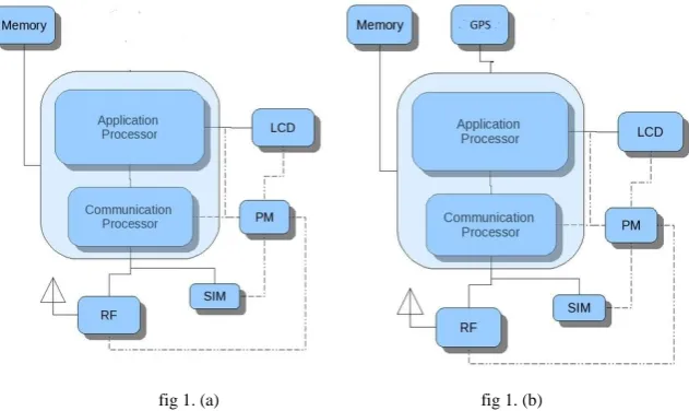
fig 1. (a) fig 1. (b)
In above figure fig 1. (a) Represents TSU (Traffic Signal Unit) Shows the block diagram of interconnection of various components present in TSU and fig 1. (b) Represents EVU (Emergency Vehicle Unit) Shows the block diagram of interconnection of various components present in TSU.(More
information of each component is given below.)
1. CPU – it consists of application processor and communication processor this unit is responsible for all arithmetic and logical operations performed by the system. All other sub systems are connected to this unit.
2. Memory – It stores the data that will be required by the CPU i.e memory will store the whole program of which some small part is being executed by the cpu.
3. LCD – it is the primary output device using which we can configure or monitor the proper working of the whole unit.
4. PM, SIM and RF- will be responsible for implement all telephony services using which a reliable connection
can be established between the Unit and the Cloud environment.
5. GPS – GPS module will be integrated only in EVU using which we can get the exact GPS Coordinates of the
2. Cloud Environment
Cloud environment will store information related to each and every Traffic Signal and Emergency Vehicle into its main database and it also have some procedures (REST Services) which are required to manipulate the database in order to achieve the objective of the system.
Signal Table – Signal table will store following data of all traffic signals present in the System
1. _id– Integer Auto increment & primary key :- This field will be unique for each and every row present in the
database. The main purpose of this field would be to uniquely identify the Traffic Signal.
2. Signal_Longitude – Integer :- This field will store the Longitude of the given signal
3. Signal_Latitude – Integer :- This field will store the Latitude of the given signal
4. Emergency_status –Boolean :- If this field will be equal to 1 then signal will show green otherwise it will work in time divided manner or any predefined manner.
EV Table – EV table will store following data for each EV present in the System.
1. _id – Integer Auto increment & primary key :- This field will be unique for each and every row present in the database. The main purpose of this field would be to uniquely identify the EV.
2. EV_Longitude – Integer :- This field will store the Longitude of the given EV. This field will be updated in
real-time as the EV moves
3. EV_Latitude – Integer :- This field will store the Latitude of the given EV. This field will be updated in
real-time as the EV moves
4. Source_Latitude - Integer :- It will Store the Latitude of the Source point.
5. Source_Longitude - Integer :- It will Store the Longitude of the Source point
6. Destination_Latitude - Integer :- It will Store the Latitude of the Destination point
7. Destination_Longitude - Integer :- It will Store the Longitude of the Destination point
Route_Table – It will store a route for each EV by means of storing traffic signals coming in its way.
1. _id – Integer Auto increment & primary key :- This field will be unique for each and every row present in the database.
2. EV_id – Integer :- This will store the _id field of EV table
3. Communication between EVU - Cloud - TSU
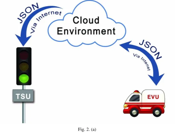
Communication between EVU and cloud will be carried out using JSON (Java Script Object Notation). Which is the data transfer format used by the android to communicate with the cloud environment.
Fig. 2. (a)
Fig. 2. (a) Model for intercommunication between EVU, Cloud Environment and TSU. This system will communicate in given way (Figure above). All the data communication will be handled by internet protocol and actual data will transfer in the form of JSON.
IV.WORKING
EVU working – following steps states that how should EVU work
1. Start
2. Setup reliable connection with the cloud
3. Get the source and destination GPS coordinates from the user.
4. Send the source and destination GPS coordinates to the Cloud Server.
5. If Acknowledgement is received.goto step 6 otherwise goto step 4.
6. Get the detailed route from the server.
7. Instruct driver of the EV to Follow the Given Route.
8. As EV starts moving send the current GPS coordinates of the EV to the cloud (Tracker algorithm). Every 5
second
9. Stop
Route working – following steps states that how should Route_Table can be filled with the proper signal coordinates.
1. Start
2. Get the source and destination GPS coordinates from the EV.
3. Get the shortest, fastest and least traffic prone route for the given points using GMAPS API.
4. Store all the traffic signal present on the route into table Route_Table. With respect to the EV _id
TSU working – following steps states that how should TSU work
1. Start
2. Setup active connection with cloud server
3. Wait for the any push message from the cloud server
4. If “set_signal_green” message is received from the cloud (Tracker) then make the current signal green i.e. allow vehicles to move out of the intersection
5. If “back_to_normal” message is received from the cloud (Tracker) then make this signal work on time divided
manner as programmed to work initially.
6. Stop
Tracker – following steps states that how should Tracker work
1. Start
2. Get the current GPS coordinates from the EVU of a particular EV.
3. Find the next traffic signal that the EV is going to reach.
4. If the distance between EV and traffic signal is less than 500m then send push message “set_signal_green” to
that TSU. Otherwise Goto step 2.
5. If the EV passes that particular signal then send push message “back_to_normal” to that TSU.
6. If destination is not reached goto step 2. Otherwise goto step 7.
7. Stop.
V. CONCLUSION
This paper touched on key point to give a clear way to emergency purpose vehicles on road so that they can reach to their destination in least time by not stopping at the traffic intersections. Traffic intersections will be smart enough to take care for flow of traffic if there is any emergency purpose vehicle need to pass on and in normal condition, traffic intersection will work normally as discussed in earlier paper. But a practical implementation of this paper need to grass root level and then optimization can be done accordingly.
REFERENCES
[1] ALLSOP R.E.: „SIGSET: a computer program for calculating traffic capacity of signal-controlled road junctions‟, Traffic Eng. Control, 1971, 12, pp. 58–60 & LITTLE J.D.C.: „The synchronization of traffic signals by mixed integer-linear-programming‟, Oper. Res., 1966, 14, pp. 568–594
[2] PAPAGEORGIOU M., DIAKAKI C., DINOPOULOU V., KOTSIALOS A., WANG Y.: „Review of road traffic control strategies‟, Proc. IEEE, 2003, pp. 2043–2067
[3] LIST G.F., CETIN M.: „Modeling traffic signal control using Petri nets‟, IEEE Trans. Intelligent Transport. Syst., 2004, 5, pp. 177–187 [4] Elisabeth ILIE-ZUDOR “The RFID Technology and Its Current Applications”, MITIP 2006, ISBN 963 86586 5 7, pp.29-36
[5] Chong hua Li “Automatic Vehicle Identification System based on RFID”, Anti-Counterfeiting Security and Identification in Communication (ASID), 2010, pp 281-284.
[6] M. Ferreira, R. Fernandes, H. Conceic¸ ˜ao, W. Viriyasitavat, and O. K. Tonguz, “Self-organized traffic control,” in the ACM international
workshop on VehiculAr InterNETworking (VANET), pp. 85–90, 2010.
[7] O. K. Tonguz, “Biologically inspired solutions to fundamental transportation problems,” IEEE Communications Magazine, vol. 49, pp. 106–115, November 2011.