Pallavi Wamanrao Taywade
, Madhuri Narayan Savale
Civil Structural Engineer, Pune, India1 Civil Structural Engineer, Pune, India2
ABSTRACT: Every structure is subjected to some kind of dynamic loading during its life span. Various dynamic loads
include wind, waves, traffic, earthquake, blasts etc. Unquestionably earthquake forces are the most devastating one among dynamic loadings. Earthquake becomes more perilous due to high unpredictability of its occurrence. Special branch of structural dynamics called Earthquake Engineering has emerged and is dedicated to analysis of structures subjected to such seismic loadings and ultimately finding solution for sustainability of a structure in seismic event. Base Isolation is a very effective way to counteract the damaging component of seismic forces and is one of the most widely implemented and accepted Design considerations for base isolated structures & general code guidelines.
Devices used:
Comprises the explanation & working of different type of devices mostly preferred, viz elastomeric & lead rubber bearing and spherical sliding bearing.
Advantages & Limitations:
about applications of this technology under which conditions and to what type of structures this technique is most suitable.
I. INTRODUCTION
Tectonic plate movements give rise to seismic events. In any such event huge amount of energy is released. For instance energy released in 2001 Bhuj earthquake was 400 times greater than that released by atomic bomb dropped at Hiroshima in 1945. Needless to say, any such major event causes great casualties, sometime claiming lives even over number of lakhs and causing innumerable amount of property destruction. High unpredictability of its occurrence makes an earthquake even more perilous. Possibility of any such happenings cannot be ruled out in a life span of a structure located in severe seismic zones. So it‟s a moral responsibility of any structural engineer to be comprehensive with his work. With the appreciation to research in the field of structural dynamics many innovative techniques & devices has been suggested to build an earthquake resistant structure. Base isolation is one of such techniques widely accepted as seismic protection system.
II. LITERATUREREVIEW
A Base isolation technique is one of the most widely implemented seismic protection systems in earthquake prone areas. The term ‟base‟ refers to the foundation of a structure & „isolation‟ refers to reduced interaction between the ground & the structure resting over it. It is a simple design approach to reduce the earthquake damage potential. It is an implementation of flexible or sliding interface between a structure and its foundation, for the purpose of decoupling the horizontal motions of a structure, thereby reducing earthquake damage to the structure and its contents.
English doctor, J.A. Calantrients, patented a construction by putting a talc layer between the foundation and a structure. However first practical implementation was done lately in year 1969 for Pestalozzi school in Yugoslavia (now Macedonia) using rubber bearings. The building rested on solid blocks of rubber without any internal horizontal reinforcing plates, as those in practice today. The first structure to utilize isolation system with added damping was the Toetoe viaduct in North Island of New Zealand. The Isolation system consisted laminated steel and rubber bearings incorporating a specially formulated high damping natural rubber, it also contained a central lead core for energy dissipation. This type of system is referred as Lead Rubber Bearing (LRB) isolation system and nowadays of the most popular. The first building to use LRB system was William Clayton Building in Wellington, New Zealand, in 1981.
A. Need for Base Isolation
In the past, an Earthquake mainly caused collapse of buildings and fatalities. Nowadays a seismic event may also endanger the social-economical stability of large areas due to the complexity of technologically advance societies. For instance Kobe earthquake of 1995 in Japan is the first case in the history of seismic events that occurred in highly industrialized urban area, by producing enormous damage to the buildings, roads and in particular, productive systems.
The earthquake which struck Izmit in turkey on August 17, 1999, caused the fire of the biggest Turkish petrochemical plant, by leading to very difficult fuel supply and heavy pollution. Scenery similar to above might take place in other parts of the world too. Having a look at casualties, death counts are in lakhs in some of the deadliest earthquakes recorded. Need for hospitals or emergency facilities to be functioning post earthquake is clear. Expected performance level for such buildings should be “fully occupational” i.e performance level of immediate occupancy post earthquake. There is ever increasing necessity of protecting non-structural components and highly sensitive equipments. Thus, for the above mention reasons wide extension of the use of innovative anti-seismic techniques, which aim at ensuring the full integrity and operability of structures, is necessary for both new constructions and retrofit of existing buildings. Seismic isolation techniques have proved themselves to be fully mature for such a use.
III.CONCEPT
An earthquake is the result of a sudden release of energy in the Earth‟s crust that creates seismic waves. This results in enormous seismic vibrations that travel through bedrock. As the energy of the earthquake travels in waves through the ground, certain frequencies of vibration retain more energy than others depending on the mechanical properties of the surrounding soil. Every building has a fundamental frequency (usually between 5 and 0.833 Hertz) that often falls within the range of seismic frequencies.
During a seismic event floor accelerations and inter-storey drifts are caused in a structure. The basic dilemma in providing superior seismic resistance of a building is the difficulty in minimizing inter-storey drift and floor accelerations simultaneously.
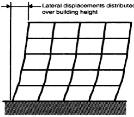
Large inter-storey drifts also causes damage to non-structural components. Inter-storey drifts can be minimized by stiffening the structure, but this leads to amplification of the ground motion, which leads to high floor acceleration, causing damage to structural components. Inter-storey drifts can be minimized by stiffening the structure, but this leads to amplification of the ground motion, which leads to high floor acceleration, causing damage to structural components. Making the system more flexible can reduce floor acceleration, but this leads to large inter-storey drifts. The only practical way of reducing inter-storey drift and floor acceleration simultaneously is to use base isolation, which provides the necessary flexibility, with the displacements concentrated at the isolation level.
Fig 1. Configuration of base isolated building.
A. Conservation of Energy
During an earthquake, a finite amount of energy is input into the structure. This input energy is transformed into both kinetic and potential (strain) energy, which must either absorbed or dissipated through heat. Following equation shows the conservation of energy in a structure during earthquake.
E = E
k
+ E
s
+ E
n
+ E
d
Whereas,
E-
Absolute energy input from earthquake motion i.e., represents the work done by total base shear force at the foundation,E
k– Absolute kinetic energy,
E
s – Recoverable elastic strain energy,E
n– Irrecoverable energy dissipated by structural system through inelastic or other forms of action andE
d – Energy dissipated by supplemental damping device.B. Behaviour of Base Isolated System Against Fixed Base System
As an earthquake shakes the soil laterally, the foundation moves with the soil and the seismic waves are transferred throughout the structure over time. If the earthquake has natural frequencies with high energy that match the natural frequencies of the building, it will cause the building to oscillate violently in harmony with the earthquake frequency. The earthquake energy loses as it moves a structure, is proportional to the stiffness of the structure. Thus, in a non-isolated state, the building itself becomes an outlet for the energy of the earthquake because in all of its structural components it has to provide tremendous resistance (force) to the seismic motion. For the above equation of conservation of energy of a structure during seismic events, magnitude of energy component En is very high and is the primary reason for failure of structure.
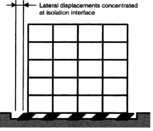
However, if the natural frequency of the building can be changed to a frequency that does not coincide with that of earthquakes, the building is less likely to fail. This is exactly what a base isolator does. The base isolator reduces the stiffness of the structure and thereby lowers its natural frequency. In this condition, the building's superstructure will respond to the vibrations as a rigid unit instead of resonating with the vibrations. Simply put, the building's foundation moves with the ground and the base isolator flexes to reduce the ground motion from affecting the superstructure. Lateral displacements caused are concentrated at isolation interface limiting the inter-storey drifts.
Fig 3. Isolated base system on earthquake.
Seismic isolation is characterized by flexibility and energy absorption capability. The flexibility alone is insufficient to defeat away a major portion of the earthquake energy so that inelastic action does not occur, i.e., En is minimized by
means of energy dissipation in the isolation system and Ed is then useful in limiting the displacement response and in
avoiding resonance.
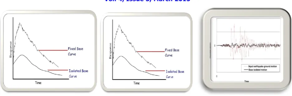
Fig 4. Time-response curve during ground accelerations Fig 5. Seismograph of base isolated systems vs. ground motions.
IV.DESIGNCONSIDERATIONSFORBASEISOLATEDSTRUCTURE
A number of factors need to be considered by an engineer, architect or owner to decide on seismic isolation for a project. Among the foremost is the evaluation of seismic hazard, which includes local geology, proximity to faults, soil conditions, characteristics of possible earthquakes such as period and severity. Subsequently, performance levels for different intensities of earthquakes need to be evaluated.
Since the isolators carry large vertical loads and deform to significant lateral displacement, the components of the structure above and below the isolator need to be designed appropriately. Plane of isolation may be chosen based on the practical aspects of installation and relative strengths of super and sub structure components.
For the isolation system to work properly, the structure should be free to move in any direction up the maximum specified displacement. Typically a seismic moat is provided around the structure to allow this movement. It is imperative that owners and occupiers of seismically isolated structures are aware of the functional importance of seismic gap and the need for this space to be left clear.
To maintain the functional purpose of the structure after a seismic event, all the utilities, electrical connections and waste pipelines should be designed to accommodate the maximum seismic displacement. The main connections between the building and the ground, such as stairs, entryways and elevators need to be unconnected across the isolation plane. In general, all the interaction between the structure and the ground need to be designed and detailed. Seismic isolation provides immediate occupancy performance level following strong events. Costs and benefits of different approaches may be evaluated in determining the incorporation of seismic isolation.
V. DESIGNPARAMETERSFORBASEISOLATIONSYSTEMS
Design of base isolated buildings is not yet included in any Indian standard code for regulations on construction works. 2000 National Earthquake Hazards Reduction Program (NEHRP, United States) & 2000 International Building Code (IBC) are some of the codes which provides general guidelines given for design of base isolation systems.
A. General Philosophy Followed by the Codes.
No specific isolation systems are described.
All isolation systems must :
Remain stable at the required displacement
Provide increasing resistance with increasing displacement.
Have non-degrading properties under repeated cyclic loading.
B. Design objectives of 2000 NEHRP and 2000 IBC Base Isolation Provisions.
No damage to structural elements
No damage to non-structural components
No damage to building contents. Major Earthquakes
No failure of isolation system
No significant damage to structural elements
No extensive damage to structural components
No major disruption to facility function
Life safety.
VI.ISOLATIONDEVICES
Successful seismic isolation of a particular structure is strongly dependent on the appropriate choice of the isolation system. The isolation system should essentially be Able to support the structure and remain rigid under service load and minor earthquakes
Able to provide horizontal flexibility to increase period of vibration and thus reducing force response
Able to dissipate energy to control isolation system displacement
These three functions could be concentrated into a single device or could be provided by means of different components. In addition to these basic requirements, it is desirable that isolation system should be rigid for low lateral loads so as to avoid perceptible vibration during frequent minor earthquakes or wind loads.
Concept of base isolation appears to have an irresistible attraction to inventors, and many new and different systems of isolators are proposed and patented each year. Many of which might prove to be impractical, but the number continues to increase year by year. Most of the practical systems today incorporate either elastomeric bearings, with the elastomer being either natural rubber or neoprene, or sliding bearings, with the sliding surface generally being Teflon and stainless steel. Some of most popular base isolation devices are briefly discussed here
A. Laminated Rubber (Elastomeric) Bearings :
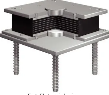
Fig 6 Elastomeric bearings
Rubber bearings offer the simplest method of isolation and are relatively easy to manufacture. The bearings are made of vulcanization bonding of sheets of rubber to thin steel reinforced plates. The bearings are stiff in vertical direction and very flexible in horizontal direction. High vertical stiffness of these bearings is achieved through the laminated construction of the bearing using steel plates. The ratio of vertical stiffness and horizontal stiffness should be high and the desired value is in the range of 200 to 500.
Fig 7. Viscous Fluid Damper (Passive damping device)
Thus for energy dissipation often passive mass dampers are incorporated along with these bearings. However, development of a natural rubber compound with enough inherent damping to eliminate the need for supplementary damping elements was achieved in 1982 by Malaysian Rubber Producers Research Association of the United Kingdom. The damping is increased by adding extra fine carbon blocks, oils and resins and other proprietary fillers. Bearings are either rectangular or circular in shape and force-displacement behavior generally linear.
The most common elastomeric used in elastomeric bearings are natural rubber, neoprene rubber, butyl rubber and nitrile rubber. Butyl rubbers are suitable for low temperature applications and nitrile rubber has limited application in offshore oil structures. Many buildings in Europe have been built on rubber bearings to isolate them from vibration due to underground railways.
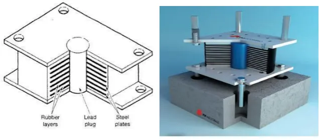
B. Lead Rubber Bearings
Fig 6. Lead Rubber Bearings Fig 7. Model showing section of Lead Rubber Bearing system.
The lead-plug rubber bearing was invented in New Zealand in 1975 and has been used extensively in New Zealand, Japan and United states. Lead Rubber bearing consists of a laminated elastomeric rubber bearing equipped with lead cylinder at the centre of the bearing as depicted in Figure 6.
The function of the rubber steel laminated portion of the bearing is to carry the weight of the structure. This bearing consists of alternate horizontal layers of steel and rubber, same as in case of elastomeric bearings. Steel provides the vertical stiffness to isolation system and is rigid under service loads. Whereas, lead core provides energy dissipation
and resists excessive displacement under high lateral loads. The lead cylinder extends throughout the full depth of the
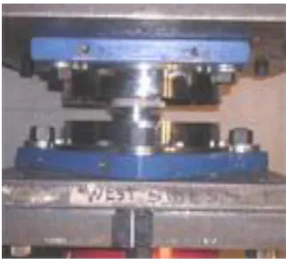
Fig 8. Force-displacement curve for Lead Rubber Bearing Fig 9. Actual photograph of installed Lead Rubber Bearing system.
Buildings isolated with these bearings performed well during some major earthquakes. One of the most recent examples involved the USC university Hospital, Isolated by Lead Rubber Bearing in 1991. In the 1994 Northridge earthquake, the hospital suffered no damage and remained operational while an adjacent hospital complex without isolators sustained about $400 million in damages.
C. Spherical Sliding Bearings
Title Spherical sliding bearing (also known as Friction pendulum) is another type of base isolation device. In this base isolation system the building is supported by bearing pads that have a curved surface and low friction. During an earthquake the building is free to slide on the bearings. Since the bearings have a curved surface, the building slides both horizontally and vertically.
Fig.10. Working of friction pendulum against simple pendulum
The period of friction pendulum using the pendulum principle can be adjusted by changing the radius of the sliding surfaces. Friction Pendulum also provides a restoring force due to gravity. In addition, sliding surfaces on the plates provide for significant displacement in a compact device. With this device it is possible to set the oscillation period of a building regardless of its weight.
Coefficient of friction is very important parameter that affects the seismic response of the sliding system considerably. The value of coefficient of friction generally varies from 0.10 to 0.24, depending upon the number of storeys of the chosen building. It is assumed that value less than 0.10 would be difficult to obtain in actual building construction and
for a value greater than 0.24 practically no advantage may be derived in FPS during some severe ground motion. High performance seismic isolation can be achieved for light buildings for which conventional methods have been considered impractical. This system can reduce costs not only because of the low cost of the device, but also due to low installation cost. Simple device works well, is easy to install, saves space and is practical for a seismic reinforcement (retrofit).
Fig 11. Actual Photograph of Sliding Bearing
VII.ADVANTAGES&LIMITATIONS
A. Advantages
A base isolation effectively protects structures against extreme earthquake without sacrificing performance during
the move frequent, moderate seismic events. With the conventional methods of building earthquake resistant structures, structure may survive of the earthquake but it is very likely that it may not remain operational after any major seismic event. But base isolation technique not only prevents the earthquake from any serious damages but also maintains functionality i.e building remains operational after earthquake.
may be having high strength and could be capable of resisting earthquake, sometime no inter-storey drifts are permissible such as in case of museums, hospitals where value of the content is more than the structure itself and thus movement of valuables cannot be afforded
This system is a saviour when it comes to safety and prevention of infrastructure of the nation such as hospitals, bridges, nuclear power plants etc from the major disastrous seismic events. This system has proven its necessity when structure is situated in seismic zone.
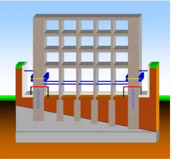
Though the process in itself is much complicated, but for conceptual explanation following pictures shows the stages of retrofitting (i.e. application of this technology to existing structures) using a simple 2D frame.
Fig 11.1 Consider above framed structure which has to be seismically retrofitted. Its basement has been excavated retaining walls at the ends has been provided to resist the lateral displacement of surrounding soil.
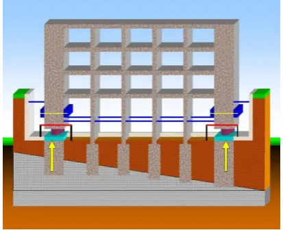
Fig 11.3 Cavity is generated in a member at base for installation of isolators.
Fig 11.4 And thus the base isolators are installed.
B
.
LimitationsBase isolation enables the reduction in earthquake-induced forces by lengthening the period of vibration of the
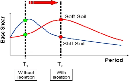
structure. However, Base isolation is not suitable for all buildings. Most suitable candidates for base-isolation are low to medium-rise buildings rested on hard soil underneath; high-rise buildings or buildings rested on soft soil are not suitable for base isolation.. Period of vibration in building increases with increasing height. Taller buildings reach a limit at which the natural period is long enough to attract low earthquake forces without isolation. Therefore, seismic isolation is most applicable to low and medium rise buildings and becomes less effective for tall ones. The cut off mainly depends on structural systems or type of framing system.
Fig. 12 Time Period of base isolated & non base isolated on soft & stiff soil.
Soft soil ground condition isn‟t suitable for base-isolated structures. After LRB yield, the structure period corresponding to the equivalent linear stiffness can be further prolonged. As a result, the natural period just enters into the range of the predominant period of earthquake wave. It leads to the acceleration amplification which makes the enlargement of seismic energy response. Consequently, it should be paid much attention on the design of absorption and isolation for base-isolated structures under the soft soil ground condition.
Requirement of tests on prototype bearing of every type increases the cost of the project. Therefore, development and standardization of testing methods for evaluating the properties of isolation devices should be formulated.
CASESTUDY
It has become evident in recent times that base isolation can be very effective in the event of an earthquake. The cost of installing base isolation systems has been so great that it is generally only used for emergency centres, historical buildings, and buildings housing very expensive and sensiti6ve equipment and are limited to developed nations only and in a developing country like India, base isolation technique is as good as nonexistent. Having technological & research institutes in almost every part of a country, still research in this field is limited to few IITs only. The only instance of base isolation in India is at district hospital. constructed post 2001 bhuj earthquake incorporating lead rubber bearing system Cost involved in constructing a new building is higher than the cost of conventional earthquake resistant structural system. Seismic isolation bearings are expensive. Due to these economic considerations, even in developed countries these devices have so far been used for important buildings only. To enable its use for common buildings, some low cost devices have to be developed.
Requirement of tests on prototype bearing of every type increases the cost of the project. Therefore, development and standardization of testing methods for evaluating the properties of isolation devices should be formulated.
CASESTUDY
It has become evident in recent times that base isolation can be very effective in the event of an earthquake. The cost of installing base isolation systems has been so great that it is generally only used for emergency centres, historical buildings, and buildings housing very expensive and sensiti6ve equipment and are limited to developed nations only and in a developing country like India, base isolation technique is as good as nonexistent. Having technological & research institutes in almost every part of a country, still research in this field is limited to few IITs only. The only instance of base isolation in India is at district hospital. constructed post 2001 bhuj earthquake incorporating lead rubber bearing system
Fig: 14 Rubber bearing provided to Bhuj hospital.
Fig: 15 Indian scenario for base isolation
Some examples of low cost isolation system include rubber bearings reinforced with fibre glass mesh instead of steel (this reduces weight as well as cost of the bearings to great extent).
Fig.16 Scrap tyre pad as low cost isolator device.
Scrap rubber tyre pads can also be utilized for isolating a building. Since the tires are being designed for friction, load transfer between scrap tire layers would be large enough to keep all layers intact. A minimal slip generated between the piled layers at high strain rates may even help to dissipate some extra energy. Steel mesh in tyre can be assumed to provide vertical rigidity to an extent. Rectangular shaped layers cut from tread sections of used tires and then piled on top of each other to form Scrap Tire Pad (STP) can function as an elastomeric pad
VII. CONCLUSION
Seismic base isolation method has proved to be a reliable method of earthquake resistant Design. The success of this method is largely attributed to the development of isolation devices and proper planning. Different types of isolation devices have been proposed and extensive research has been made on them.
They can serve the purpose for almost all types of conditions. Adaptable isolation systems are required to be effective during a wide range of seismic events. Besides, the existing devices are expensive and to make isolation feasible for ordinary buildings, it is efforts are required to develop cost effective devices.
REFERENCES
1. Andrew Jacobs, Base Isolation. On the WWW, URL http://illumin.usc.edu/article.php?articleID=127&page=1
2. Michael D. Symans, Seismic protective systems: Seismic Isolation. On the WWW, URL http://www.nibs.org/client/assets/files/bssc/Topic15-7-SeismicIsolation.pdf .PDF file.
3. Andrew W. Taylor, Takeru Igusa, Primar on Seismic Isolation. Search engine www.books.google.com. 4. Farzad Naeim & James M. Kelly , Design of Seismic Isolated Structures.
5. Bayezid Özden, Low Cost Seismic Isolation Using STP. On the WWW, URL http://etd.lib.metu.edu.tr/upload/12607193/index.pdf .PDF File. 6. Catalogue of Robinson Seismic Bearings, On the WWW, URL
http://www.rslnz.com/?pageRequired=showDoc&item=9http://www.robseis.bengeweb.co.nz/?pageRequired=showDoc&item=9 7. Videos on shake table test & base isolation by world news. On the WWW, URL http://wn.com/base_isolation.
8. Buildings having Base Isolation Systems. On the WWW, URL http://civil-engg- image.blogspot.com/2009/07/buildings-having-base-isolation.html
9. Friction Pendulum System. On the WWW, URL 10. http://www.oiles.co.jp/en/menshin/building/isolate/fps.html
11. Seismic Base Isolation Technique for Building Earthquake Resistance on WWW, URL
http://articles.architectjaved.com/earthquake_resistant_structures/seismic-base-isolation-technique-for-building-earthquake-resistance/ 12. How base isolation originated - Video by Dr. Bill Robinson, on WWW, URL