MWF-NW Algorithm for Space-Time Antijamming
Fulai Liu1, 2, Miao Zhang2, Fan Gao2, *, and Ruiyan Du1, 2
Abstract—Space-time antijamming problem has received significant concern recently in global navigation satellite. Space-time null widening technique is an effective technique to suppress interference signals in the case of rapidly moving environments. However, the computational complexity of traditional null widening algorithms is usually so high that it is difficult to apply in engineering problems. In order to solve this problem, a novel null widening algorithm based on multistage wiener filter (named as MWF-NW algorithm) is proposed for reducing the computational complexity of space-time antijamming algorithms. By using the Hadamard product and Khtri-Rao product, the space-space-time covariance matrix taper problem can be transformed into a space-time data taper problem. Then, the dimension of the tapered data is reduced by multistage wiener filter theory, and the optimal weight vector is also given by multistage wiener filter theory. Thus the algorithm can reduce computational complexity significantly and suppress interference signals effectively when the receiver is shaking. Simulation results are presented to verify the feasibility and effectiveness of the proposed algorithm.
1. INTRODUCTION
Global navigation satellite system (GNSS) provides accurate position and velocity information to users with appropriate receiving equipment at any time [1]. However, due to the long distance between satellite and receiver, the power level of satellite signals is so weak that the performance of GNSS can be affected by various interference signals, thus the performance of navigation and positioning might dramatically descend. In real application, the receiver usually moves with large rate change of the motion velocity in practical applications such as the maneuvering flight of fighter aircraft and target tracking in the course of missile [2]. In this case, it is possible that the mismatch may occur between the weights and data, and the interference signals may move out of the narrow nulls formed by conventional antijamming algorithm easily [3]. Thus, the performance of the antijamming algorithm may degrade dramatically under aforementioned scenarios. In order to solve such problems, space-time null widening technique is presented to suppress the interference signals when the receiver moves with high velocity. By adding virtual interference around the direction of the interference signal and constructing covariance matrix, a null widening algorithm is proposed by Mailloux [4]. Zatman also gives a null widening algorithm by expanding the bandwidth of the interference signal [5]. Through generalizing the algorithm proposed by Mailloux and Zatman, a concept of “Covariance Matrix Taper (CMT)” is given by Guerci [6]. By using the convex programming technique, the width of null can be broadened, and the sidelobe level can be controlled effectively. Unfortunately, the computational complexity of this algorithm is high [7]. A new null widening adaptive beamforming algorithm combined with projection transform and diagonal loading is given in [8]. The diagonal loading technique and received data transform technique based on the subspace projection are used to gain a new sample covariance matrix. This method can effectively broaden the width of jammer nulls and strengthen the null depth. A robust beamforming algorithm
Received 5 December 2018, Accepted 24 January 2019, Scheduled 10 February 2019 * Corresponding author: Fan Gao (gaofan [email protected]).
1 Engineer Optimization & Smart Antenna Institute, Northeastern University at Qinhuangdao, China.2School of Computer Science
166 Liu et al.
based on nulls optimization is proposed in [9]. The width of the formed null is widened by the rotation of the steering vector, and the received data are projected into the interference subspace. Thus the algorithm can broaden the nulls of interference signals as well as guarantee the gain of the desired signal. Using covariance matrix augmentation method and dispersion synthesis, a new null widening algorithm is proposed based on random array. The feasibility in engineering of the algorithm is verified [10]. Unfortunately, all of the algorithms given above may have a high computational complexity in the process of gaining optimal weights.
In order to avoid the process of inverting the covariance matrix, more and more experts and scholars begin to study dimensionality reduction and iterative algorithms, which can avoid the process of finding the inverse of covariance matrix and greatly reduce the computational complexity of the algorithm. The householder multistage wiener filter is improved to suppress the influence of impulsive noise spikes from desired signal direction of arrival. This algorithm adopts samples section method to avoid the influence of weights calculation and can gain good performance in both of narrow band and wideband interference signals [11]. Diagonal loading technique is added to the multistage wiener filter to improve the robustness of beamformers, and two forms of diagonal loading are given [12]. To reduce the complexity of the algorithm, a multi-stage wiener filter based adaptive process for antijamming is designed in [13]. By using this algorithm, the signal is projected to orthogonal space and filtered step by step. Simulations show that this algorithm can satisfy the real time processing requirement of navigation signal. An iterative realization method of minimum variance distortionless response beamforming algorithm is presented in [14]. An antenna structure based on four circular patches is proposed in [15], and the main lobe is steered towards a desired direction to obtain an optimal management of wireless resources. In [16], some advantages and potentialities of the integration of smart antennas in a Wireless Sensor Network (WSN) architecture is envisaged by means of a set of experiments dealing with test configurations. In [17], a method for the synthesis of a microstrip switched-beam antenna array with a compact and efficient feeding network is proposed, which is a better candidate for modern wireless sensors that require cheap, efficient and compact radiating systems. The computational complexity is reduced by avoiding matrix inversion operation of the iterative realization method. By choosing the data length properly, interference signals can be suppressed effectively.
However, the dimensionality reduction and iterative algorithms given above are not combined with null widening technique. In order to reduce the computational complexity of null widening algorithm, in this paper, an MWF-NW algorithm is proposed. By using multistage Wiener filter theory, the computational complexity can be reduced significantly. The rest of the paper is organized as follows. The data model is described in Section 2. Section 3 introduces the proposed method. Section 4 gives some simulation results. Finally, the conclusion is summarized in Section 5.
2. DATA MODEL
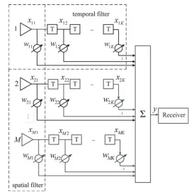
The structure of a uniform circular array (UCA) with M elements is shown in Figure 1. Each element in the UCA is equally spaced withK taps, and the space-time filter structure is given in Figure 2.
The space-time observation signal x(t) = [x11, x12, . . . , x1K, . . . , xM K]T can be expressed as
x(t) =us(t) + Q
q=1
gqjq(t) +n(t) (1)
where s(t) denotes the desired satellite signal, and jq(t) denotes the qth interference signal. n(t) represents the white Gaussian noise of antenna array. u and gq stand for the space-time steering vector of the desired satellite signal and theqth interference signal, which have the following forms
u=a(θ0, φ0)⊗at(T)
gq =a(θq(t), φq(t))⊗at(T) (2) whereθ0 and φ0 are the azimuth angle and pitch angle of the desired satellite signal. θq and φq are the azimuth angle and pitch angle of theqth interference signal. a(θ, φ) andat(T) in Eq. (2) can be written as
a(θ, φ) = [e−jvT(θ,φ)p1, e−jvT(θ,φ)p2, . . . , e−jvT(θ,φ)pM]T
Figure 1. Uniform circular array model. Figure 2. Space-time filter structure.
wherea(θ, φ) is the space steering vector of the array, andat(T) is the time steering vector. T denotes the time delay in Figure 2. The superscript (·)T represents the transpose operation. The vector v and position vector of themth elementpm have the following forms
v(θ, φ) = 2π λ
sinθ cosφ sinθ sinφ
pm=r[cosrm,sinrm]
(4)
wherer is the radius of the UCA andrm = 2π(m−1)/M.
Thus, the beamformer output of the space-time filter can be expressed as
y(t) =wHx(t) (5)
where w= [w11, w12, . . . , w1K, . . . , wM1, . . . wM K]T is the M K×1 weight vector. The superscript (·)H denotes the conjugate transpose.
3. ALGORITHM FORMULATION
3.1. Null Widening Method
When the receiver is shaking, incident direction of the interference signal changes continuously with time, and it is not guaranteed to be incident at a fixed angle. In this case, under the uniform circular array, the azimuth and pitch angles can be expressed as follows.
¯
θq=θq+ Δθq ¯
φq=φq+ Δφq (6)
168 Liu et al.
ξq22(Δφq ∼N(0, ξq22)). The above model is used in [18] and [19] to describe the distributed targets and transmit characteristics of mobile communication. Thus, the mean covariance matrix can be given by
¯
RL(m, n) = Q
q=1
σ2q
f(Δθq,Δφq)e−j[pm−pn]
Tv(¯θq,φ¯q)
d(Δθq)d(Δφq) +σ2eδmn (7)
where σ2q and σe2 denote the power of the qth interference signal and noise signal, respectively. f(Δθq,Δφq) stands for the joint probability density function of (Δθq,Δϕq). The vectorv and position vector pm are given in Eq. (4). The vector v(¯θq,φq¯ ) can be expressed in Eq. (8). δmn can be expressed in Eq. (9).
v(¯θq,φ¯q) = v(θq+ Δθq, φq+ Δφq). (8)
δmn =
1 m=n
0 m=n (9)
Owing to the extension angle Δθq and Δφq are statically independent of each other. Thus, the vector v(θq+ Δθq, φq+ Δφq) in (8) can be simplified by Taylor series, and ¯RL(m, n) can be written as
¯
RL(m, n)≈ Q
q=1
σq2e−j2λπ[pm−pn]Tv(θq,φq)AmnBmn+σ2eδmn (10)
whereAmn andBmn in Eq. (10) can be expressed as
Amn=
f(Δθq)e
−j2λπ[pm−pn]T
cosθqcosφq cosθqsinθq
Δθq
d(Δθq) = exp(
ξq21D2mn
2 )
Bmn=
f(Δφq)e
−j2λπ[pm−pn]T
−sinθqsinφq sinθqcosθq
Δφq
d(Δφq) = exp(
ξ2q2Fmn2 2 ).
(11)
Introduce an extension matrixTL, and each element inTL can be expressed as
TL(m, n) = exp(ξ 2
q1D2mn
2 )exp(
ξ2
q2Fmn2
2 ). (12)
In order to gain the biggest extension angle, whenξq1=ξq2 =ξq, Eq. (12) can be simplified as
¯
TL(m, n) = exp −ξ 2 q 2
G2
mn+Hmn2
(13)
whereGmn= 2λπr(cosrm−cosrn),Hmn= 2λπr(sinrm−sinrn).
Utilizing the extension matrix ¯TL in Eq. (13), the mean covariance matrix in Eq. (10) can be written as
¯
RL=Rx◦T¯L. (14)
where “◦” represents the Hadamard product of the covariance matrixRxand the expansion matrix ¯TL
for solving the received signal.
3.2. Space-Time Data Taper
Utilizing the Khatri-Rao product, received data of the array can be refactored as
RL=Rx◦TL
=x0(t)xH0 (t)
◦ΩΩH
= [x0(t)Ω] [x0(t)Ω]H
(15)
where “” represents the Khtri-Rao product of x0(t) and Ω. Let α1, α2, . . . , αM K be the row vector of the received signal x0(t), and β1, β2, . . . , βM K is the row vector of the matrix Ω. According to the definition of the Khtri-Rao product, the Khtri-Rao product of x0(t) and Ωcan be expressed as
3.3. Calculation and Solution of Weight
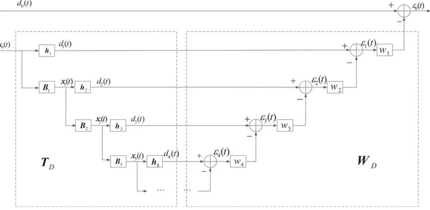
In traditional antijamming algorithm, the optimal weight is usually obtained through the process of inversing covariance matrix. Therefore, in order to reduce the computational complexity, multi-stage Wiener filter is used to reduce the dimension of the data. The multi-stage Wiener filter is proposed by Goldstein [14], and the structure of the multi-stage Wiener filter is given in Figure 3.
Figure 3. Multi-stage Wiener filter structure.
In the figure, the multi-stage Wiener filter can be decomposed into two parts: an analysis filter and a synthesis filter. hi+1 is a normalized cross-correlation vector. By calculating the cross-correlation vectorrxidi ofxi(t) anddi(t), then normalizing it, a vectorhi+1can be obtained, which has the following form:
hi+1 =
rxidi
rxidi (17)
By utilizing the vector hi+1, data information associated with di(t) can be extracted from data
xi(t). In the figure,Bi is a (M K−i)×M K dimensional blocking matrix, which can be expressed as
Bi =null(hi) (18)
The blocking matrixBi is the zero space of the vectorhi, which is Bihi =0. In the final level of decomposition, let xN−1(t) = dN(t) = εN(t), then be synthesized by a set of recursive scalar Wiener filters. An output error signal ε0(t) of the Wiener filter is obtained. Therefore, in the synthesis filter, wi in each stage can be expressed as
wi=R−εi1rεidi−1 (19)
whereRεi = E[|εi(t)|2], rεi+1di can be expressed as
rεi+1di =E[εi+1(t)d∗i(t)] =hHi+1rXidi =
rH
XidirXidi (20)
whererXidi =E[xi(t)d∗i(t)] and the result of the above formula is recorded asδi+1. Therefore, Eq. (19) can be expressed as
wi = R−εi1rεidi−1 =ηi−1δi (21)
ηi = E
|εi(t)|2
=Edi(t)−w∗i+1εi+1(t) 2
=σd2i−ηi−+11|δi+1|2 (22)
whereσ2
di =E[|di(t)|
2] =hH
170 Liu et al.
According to the above derivation process and the multi-stage Wiener filter structure shown in Figure 3, the output error signalε0(t) can be expressed as
ε0(t) =d0(t)−w∗1ε1(t) =d0(t)−w∗1(d1(t)−w2∗ε2(t)) =d0(t)−wHnd(t) (23) where wn represents an equivalent weight vector after dimension reduction, and the weight vector wn
and vector d(t) can be expressed as
wn=
w1,−w1w2, w1w2w3, . . .(−1)N+1 N
i=1
wi T
d(t) = ⎡
⎣hH1 ,hH1 B1, . . . ,hHN−1 1
j=N−2
Bj, 1
j=N−1
Bj
⎤ ⎦ H
x0(t) =TNHx0(t)
(24)
By bringing Eq. (24) into Eq. (23), ε0(t) can be expressed as
ε0(t) =d0(t)−(TNwn)Hx(t) (25)
Therefore, the weight vector of the multi-stage Wiener filter with the decomposition level ofN can be obtained, which is recorded as wM W F.
wM W F =TNwn (26)
3.4. Computational Complexity Analysis
3.4.1. MWF-NW Algorithm Computational Complexity Analysis
Suppose that a space-time uniform circular array contains M array elements, and each array element is equally spaced with K taps. The snapshot is recorded as N. The dimension of the space-time array receiving data x0(t) is in M K×N dimension. In the MWF-NW algorithm, assuming that the multi-stage Wiener filter needs to be decomposed d times, and the computational complexity of the MWF-NW algorithm can be analyzed as follows:
In the decomposition filter, the computational complexity of each decomposition is O(M KN), and assuming that the number of decompositions is d, the computational complexity of the process is O(M KN d). In the synthesis filter, assuming that the number of decompositions is d, the number of iterations of the synthesis filter is d, where the computational complexity of each iteration is O(N), and the computational complexity of the second iteration is O(N d). In summary, the computational complexity of the MWF-NW algorithm is O(M KN d) + O(N d).
3.4.2. Mailloux Algorithm Computational Complexity Analysis
In the space-time receiving array where the number of elements isM, and the number of taps isK, the complexity of the Mailloux algorithm is analyzed as follows:
The received signal covariance matrix ˆRx is calculated by M K ×N dimensional space-time receiving data x0(t). The dimension of the received signal covariance matrix ˆRx is M K ×M K.
From ˆRx=K1 K
k=1
x(t)xH(t), the computational complexity of the calculation ˆRx is O((M K)2N). In
the process of covariance matrix taper, according to Eq. (14), the computational complexity of the covariance matrix taper is O((M K)2). In the solution of the weight vector, it is necessary to inverse the modified covariance matrix ¯RM. The computational complexity of the inversion process is O((M K)3). In summary, the total complexity of the Mailloux algorithm is O((M K)2N) + O((M K)2) + O((M K)3).
3.4.3. DC-NW Algorithm Computational Complexity Analysis
In order to analyze the computation complexity clearly, the computation complexity of these three algorithms is given in Table 1.
Table 1. Analysis of computation complexity.
Algorithm Computation complexity
MWF-NW O(M KN d) + O(N d)
Mailloux O((M K)2N) + O((M K)2) + O((M K)3) DC-NW O((M K)2N) + O((M K)3)
Compared with the other two algorithms, the MWF-NW algorithm requires fewer sample snapshots, and d < M K. Therefore, the computational complexity of the proposed MWF-NW algorithm is significantly lower than that of the other two algorithms. The main reason is that the algorithm avoids the operation of inverting the covariance matrix in the process of obtaining the weight vector, thus greatly reducing the computational complexity.
Summary of the Proposed Method
Step 1. The space-time data are tapped by Eq. (16) receiving datax(t) from the array antenna, and the received datax0(t) after taper are obtained.
Step 2. According to Eqs. (17)∼(19), the received data reconstructed in Step 1 are decomposed using an analysis filter of the multi-stage Wiener filter. Find the scalar weight of each level of the Wiener filter.
Step 3. According to Eq. (23), the output error signal of each stage Wiener filter can be calculated.
Step 4. The reduced dimension matrix can be computed by Eq. (24).
Step 5. The weights of each level in Step 2 are iteratively processed, and the dimensionality reduction matrix obtained in Step 4 is utilized. The final weight vector is obtained according to Eq. (26).
4. SIMULATION RESULTS
This section gives simulations of the proposed algorithm. In the simulation experiment, the uniform circular array consists of 7(M = 7) array elements, and 5(k = 5) taps are used. The signal to noise ratio (SNR) is −17 dB. The jam to signal radio is 54 dB. The azimuth and pitch angles of the satellite signal are (280◦,30◦). Assume that only one interfering signal is incident, and the azimuth and pitch angles of the interference signal are (80◦,45◦). Due to the motion of the receiver, the azimuth and pitch angles change from (80◦,45◦) to (80◦,50◦). The weight is obtained when the interference signal incident azimuth and pitch angles are (80◦,45◦).
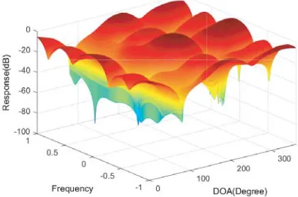
Figure 4. Space frequency response of MWF-NW.
172 Liu et al.
Figure 4 and Figure 5 give the space-time response diagram of the MWF-NW algorithm and the Multistage Wiener Filter (MWF) algorithm. It can be clearly seen from Figure 4 and Figure 5 that the azimuth angle of the incident signal is 80◦, and the number of incident interference signals is one. Both algorithms are capable of forming a deeper null in the direction in which the interfering signal is incident. It is expected that the satellite signal will have an azimuth of 200◦. Both algorithms can form the main lobe in the direction in which the satellite signal is expected to be incident, and the interference signal can be suppressed to the maximum while ensuring the distortion-free output of the desired signal.
Figure 6 and Figure 7 show the array beam patterns of the proposed MWF-NW algorithm and MWF algorithm, respectively. It can be seen from the figure that the number of incident interference signals is one. Compared with the MWF algorithm, the data of the MWF-NW algorithm are reconstructed, thus the formed null of MWF-NW algorithm has a certain degree of broadening in the azimuthal direction and pitch angle direction of the incident signal. The anti-jamming performance of the algorithm is improved.
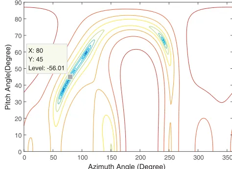
Figure 8 is a top view of Figure 6, and Figure 9 is a top view of Figure 7. The MWF algorithm forms a null in the direction of interference incidence, but the width of the null is narrow. The MWF-NW algorithm not only forms a wide null in the azimuthal direction of the incident signal, but also forms a
Azimuth Angle(Degree) 60 300 Pitch Angle(Degree) 40 200 20 100 0 0 -80 -60 80 -40 Response Gain(dB) -20 0
Figure 6. Beam pattern of MWF-NW algorithm.
Azimuth Angle(Degree) 60 300 Pitch Angle(Degree) 40 200 20 100 0 0 -80 -60 80 -40 Response Gain(dB) -20 0
Figure 7. Beam pattern of MWF algorithm.
0 50 100 150 200 250 300 350
Azimuth Angle(Degree) 0 10 20 30 40 50 60 70 80 90 Pitch Angle(Degree)
Figure 8. Contour of MWF-NW algorithm.
0 50 100 150 200 250 300 350
Azimuth Angle (Degree) 0 10 20 30 40 50 60 70 80 90 Pitch Angle(Degree) X: 80 Y: 45 Level: -56.01
-26 -25 -24 -23 -22 -21 -20 -19 -18 -17 Input SNR(dB)
-35 -30 -25 -20 -15 -10
Output SINR(dB)
MWF-NW
Mailloux
DC-NW
MWF
Figure 10. The output SINR versus input SNR.
null in the direction of the pitch of the incident signal.
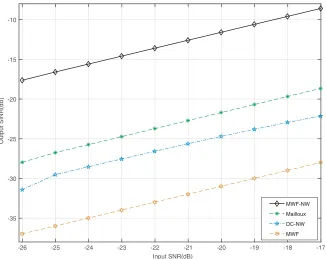
Figure 10 gives the output signal to interference plus noise ratios (SINRs) of the proposed MWF-NW algorithm, Mailloux algorithm, DC-MWF-NW algorithm, and MWF algorithm. The input SNR changes from −26 dB to 17 dB. From the figure, obviously, with the growth of the input SNR, all the output SINRs of these four algorithms increase linearly. In the same simulation environment, the output SNR of the MWF-NW algorithm is higher than the MWF algorithm. Compared with the Mailloux algorithm and DC-NW algorithm, when the receiver is shaking, the SINR of the MWF-NW algorithm is about 10 dB and 14 dB higher than that of the Mailloux algorithm and DC-NW algorithm. According to the above analysis, the multi-stage Wiener filter is used to obtain the weight vector, and the process of inversing covariance matrix is avoided. Therefore, compared with the other three algorithms, the MWF-NW algorithm has lower computational complexity and better performance.
5. CONCLUSIONS
This paper presents a novel null-widen algorithm based on a multistage Wiener filter which can reduce the computational complexity and can be applied to engineering problems easily. The algorithm first uses the relationship between the Hadamard product and Khtri-Rao product to reconstruct the received data, then uses a multi-stage Wiener filter to perform step-by-step dimensionality reduction on the reconstructed received data. Finally, the process of inverting the covariance matrix is transformed into a process of retrieving multiple scalars. This reduces the complexity of the algorithm. The results in simulation demonstrate that the proposed algorithm can form a wide null in the azimuth and elevation angles of the incident signal, and the proposed algorithm has better performance under small snapshot, which can effectively suppress the interference signal.
ACKNOWLEDGMENT
174 Liu et al.
REFERENCES
1. Hu, H. and N. Wei, “A study of GPS jamming and anti-jamming,” International Conference on Power Electronics & Intelligent Transportation System, 2010.
2. Compton, R. T., “The power-inversion adaptive array: Concept and performance,” IEEE Transactions on Aerospace &Electronic Systems, Vol. 15, No. 6, 803–814, 1979.
3. Ke, X. and N. Liu, “Research on adaptive anti-jamming and null widening algorithm for satellite navigation,” Journal of Electronic Measurement& Instrument, Vol. 24, No. 12, 1082–1087, 2010. 4. Mailloux, R. J., “Covariance matrix augmentation to produce adaptive array pattern troughs,”
Electronics Letters, Vol. 31, No. 10, 2141–2142, 1995.
5. Zatman, M., “Production of adaptive array troughs by dispersion synthesis,” Electronics Letters, Vol. 31, No. 25, 2141–2142, 1995.
6. Guerci, J. R., “Theory and application of covariance matrix tapers for robust adaptive beamforming,” ITS Telecommunications Proceedings, 2006.
7. Jafargholi, A., M. Mousavi, and M. Emadi, “Wide-band VHF nulling by five elements spiral array antenna,” Electronics Letters, Vol. 31, No. 25, 2141–2142, 1995.
8. Mao, X. J., W. X. Li, and Y. S. Li, “Robust adaptive beamforming against signal steering vector mismatch and jammer motion,”International Journal of Antennas and Propagations, Vol. 10, 1–12, 2015.
9. Li, S., “Robust beamforming algorithm based on nulls optimization,” Signal Processing, Vol. 33, No. 12, 1542–1547, 2017.
10. Shuai, S. U. and X. Wang, “Application of null broadening technique in random array adaptive beamforming,” Ship Electronic Engineering, Vol. 36, No. 01, 67–71, 2016.
11. Huang, Q. D., L. R. Zhang, and G. Y. Lu, “Interference suppression method for space-time navigation receivers based on samples selection Householder multistage wiener filter,” IEEE International Conference on Signal Processing, 2010.
12. Hiemstra, J. D., M. E. Weippert, and H. N. Nguyen, “Insertion of diagonal loading into the multistage Wiener filter,”Sensor Array &Multichannel Signal Processing Workshop, 2003. 13. Zhang, C., Z. Li, and C. Pan, “A multi-stage Wiener filter based adaptive processing device for
anti-jamming of navigation signal,” Modern Electronics Technique, Vol. 38, No. 22, 1–10, 2015. 14. Hua, Z., “Iterative realization and investigation of MVDR anti-jam beamforming algorithm,”
Electronic Measurement Technology, Vol. 36, No. 9, 37–40, 2013.
15. Donelli, M. and P. Febvre,“An inexpensive reconfigurable planar array for Wi-Fi applications,”
Progress In Electromagnetics Research C, Vol. 28, 71–81, 2012.
16. Viani, F., L. Lizzi, M. Donelli, D. Pregnolato, G. Oliveri, and A. Massa, “Exploitation of parasitic smart antennas in wireless sensor networks,” Journal of Electromagnetic Waves and Applications, Vol. 24, No. 9, 993–1003, 2010.
17. Donelli, M., T. Moriyama, and M. Manekiya, “A compact switched-beam planar antenna array for wireless sensors operating at Wi-Fi band,” Progress In Electromagnetics Research C, Vol. 83, 137–145, 2018.
18. Zetterberg, P. and B. Ottersten, “The spectrum efficiency of a base station antenna array system for spatially selective transmission,” IEEE Transactions on Vehicular Technology, Vol. 44, No. 3, 651–660, 1995.
19. Riba, J., J. Goldberg, and G. Vazquez, “Robust beamforming for interference rejection in mobile communications,”IEEE Transactions on Signal Processing, Vol. 45, No. 1, 271–275, 1997.