Implementation of UART based on BIST (Built in self
test) Architecture
Bodapati Lakshmi Durga
1, G.SrinivasaRao
2, Dr. CH. Balaswamy
3[email protected] [email protected]
[email protected]
1Ug Scholar, Department Of Ece, Qis College Of Engineering & Technology, Vengamukkapalem,Prakasam, Ongole, Andrapradesh.
2Assistant Professor, Department Of Ece, Qis College Of Engineering & Technology,
Vengamukkapalem, Prakasam, Ongole, Andrapradesh.
3Professor, Department Of Ece, Qis College Of Engineering & Technology, Vengamukkapalem,
Prakasam, Ongole, Andrapradesh.
Abstract:Testing of VLSI chips is changing into significantly complicated day by day as a result of increasing exponential advancement of NANO technology. BIST is a technique that enables a system to check mechanically itself with slightly larger system size. This paper targets the introduction of Built-in self test (BIST) and Status register to UART. Asynchronous serial communication is usually implemented by Universal Asynchronous Receiver Transmitter (UART), mostly used for short distance, low speed, low cost data exchange between processor and peripherals. The BIST used here have two modes actually i.e. test mode and UART mode. This technique generate random test pattern automatically, so it can provide less test time compared to an externally applied test pattern and helps to achieve much more productivity at the end. Simulation results for BIST enabled UART are observed by Xilinx ISE design suite.
Keywords: Built-In-Self-Test (BIST), Universal Asynchronous Receive Transmit (UART).
I. INTRODUCTION
Testing of integrated circuits (ICs) is of crucial importance to confirm a high level of quality in product practicality in each commercially and in camera made merchandise. The impact of testing affects areas of producing also as those concerned in style. This want to realize a top quality level should be tempered with the value and time concerned during this method.
In VLSI we've testing issues like input combinatorial issues, gate to I/O pin magnitude relation issues, take a look at generation issues, light-emitting diode the designer to spot reliable take a look at ways and solve this issues.teh insertion of special take a look at electronic equipment on the VLSI circuits that
enables economical take a look at ways. This has been self-addressed by the requirement for style for testability (DFT) and thus the requirement for BIST. It tests the circuit or system performs itself thus it's named as “self-test". BIST is AN on-chip take a look at logic that's utilized to check the useful logic of a chip, by it. Thanks to the speedy increase within the style quality, BIST has become a serious style thought in DFT ways and is changing into progressively vital in today’s state of the art SoCs. A properly designed BIST is in a position to offset the value of additional take a look at hardware whereas at identical time making certain the dependability, reduces maintenance value and testability.
In parallel communication the value still as quality of the system will increase because of concurrent transmission of data bits on multiple wires. Serial communication alleviates this downside and emerges as effective technique in several applications for long distance communication because it reduces the signal distortion attributable to its straightforward
structure. Universal Asynchronous Receiver
of a laptop (Personnel computer). UART performs parallel-to-serial conversion on information character received from the host processor into serial information stream, and serial-to-parallel conversion on serial information bits received from serial device to the host processor. It additionally adds the start and stop bit to the info for synchronization. Additionally to the fundamental job of changing information from parallel to serial for transmission and from serial to parallel on reception, a UART can sometimes give extra circuits for signals that can be accustomed indicate the state of the transmission media and to manage the flow of information within the event that the remote device isn't ready to just accept additional information.
II. BIST Architecture
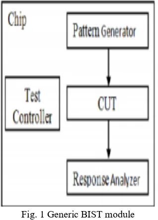
BIST architecture consists of a take a look at Pattern Generator (TPG), the circuit to be tested (CUT), some way to investigate the results (TRA), and some way to compress those results (BCU) and also LFSR for simplicity and handling. CUT could be designed as memory device architecture for testing the faults. The fault address can be detected and it could compare to the comparator for the analysis of the all relevant circuits.
Fig. 1 Generic BIST module
The LFSR generates the feedback values from the each and every flip-flop for the new CUT architecture. The level of this recognition could be
difficult to identify the fault and it could be having time consuming process. The process can be adoptable for the all authorized and the unauthorized data’s. The BIST controller can be easily controlled as a device details for the novel architecture for the further details. The test response analysis could be considered for the UART transmitting and the receiving data’s form the each bits. The test results can be detecting the fault address and then it consumes all the details as a database and identifies the fault address and shows the details. This could be as a process of simulation level waveform.
III. UART with BIST Architecture
The UART architecture contains the transmitter and the receiver. This could be contain and loads the buffer data for all the read and write operation. The data transfers through this serial communication to get the proper information about the outputs.
Figure 2: Block diagram of UART Architecture
A. UART TRANSMITTER
frame of the info and transmits the info in serial type on the Transmitter Output terminal (TxD) (Figure.3). The baud generator output will be the clock for UART transmitter into the data buffer to enable and reset the all new data’s from the input and the output registers. The transmitter controller could be accessed as a terminal data for the buffer usage from the control section.
Figure 3: Block of UART Transmitter
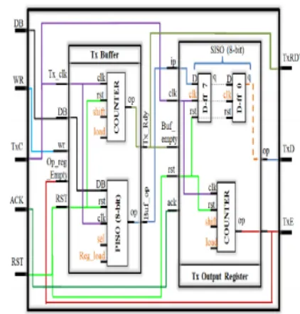
UART transmitter module consists of an output register, a transmitter buffer register and transmitter control logic. The i/o pins are:
• TxD is the port for serial data output • TxC bar is the transmitter clock input • TxE is the transmitter control logic • ACK & RST are two control inputs
Fig 4: Internal architecture of UART transmitter
The PISO block shown in Fig 4 takes 2 input signals PISO_sel and Reg_load. The first one is used to derive third function of the block i.e. hold the data bits when output register is not ready-this is done just by deactivating the clock inside the block. The 2nd one i.e Reg_load is high when 8 data bits are loaded parallel in PISO register i.e. when output register is ready, the Counter_3_bits counts and all 8bits are shifted from PISO to Tx_Out_Reg.
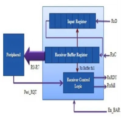
UART Receiver Section
Figure 5 shows the architecture of UART receiver section. The followings are the brief description of each block.
Fig 5: UART receiver section architecture
IV. LFSR GENERATOR
The most ordinarily used linear perform of single bits is exclusive-or (XOR). Thus, Associate in LFSR is most frequently a register whose input bit is driven by the XOR of some bits of the register worth. The initial worth of the LFSR is termed the seed, and since the operation of the register is settled, the stream of values made by the register is totally determined by its current (or previous) state. Likewise, as a result of the register encompasses a finite variety of potential states, it should eventually enter a repetition cycle. However, Associate in Nursing LFSR with a felicitous feedback perform will manufacture a sequence of bits that seems random and that encompasses a terribly long cycle.
Figure 6: LFSR Block
Test vector inhibiting techniques separate out some non-detecting subsequences of a pseudorandom take a look at set generated by associate degree LFSR. These architectures apply the minimum variety of take a look at vectors needed to attain the required fault coverage and thus cut back power. Many low power methods are projected for full scan and scan-based BIST design.
Fig.7 Port mapping and the internal components of LFSR
In this figure 7 a LFSR of polynomial X8+X6+X5+1 is made. A PISO with one 3 bit down counter & one 1 CLk delay component is connected. O/P from all DFF comes to the PISO , PISO has another two I/P sel & Reg_load & one PS O/P which serially fed to the receiver.3 bit down counter with 1 CLK delay is connected to the Reg_load of PISO. Now when sel is zero O/P from DFF is fed to the receiver serially with every count of the down counter (counter CLK is the trigger signal from comparator). Now when counter value goes to zero i.e 8 bit data has been send to the receiver then PISO will send all 8 bit data parallel to the transmitter in one clock period.
RTL Schematic.
Technology Schematic.
Design Summary.
Timing Summary.
VI. CONCLUSION
The architecture of UART that support 8-bit data for serial transmission of data with the addition of status register for detecting errors in data transfer and BIST which allows to test the circuit itself, is introduced. Working of UART has been tested using Xilinx ISE simulator, which is implemented on FPGA. With error checking status register, we can detect the
different types of errors occurred during
communication and hence correct them. With the implementation of BIST, expensive tester requirements and testing procedures starting from circuit or logic level to field level testing are minimized. The LFSR replaces the function of the external tester features such as a test pattern generator by automatically generating pseudo random patterns to give good fault coverage to the UART module. Although the additional BIST circuit increases the hardware overhead and design time, it eliminates the need to acquire high-end testers. The reduction of the test cost helps in the reduction of overall production cost.
REFERENCES
[2] Dr. T.V.S.P. Gupta, Y. Kumari,M.Asok Kumar”UART realization with BIST architecture using VHDL” International Journal of Engineering Research
and Applications (IJERA) ISSN: 2248-9622
www.ijera.com Vol. 3, Issue 1, January -February 2013, pp.636-640
[3] M.S. Harvey,Generic UART Manual,Silicon Valley,December 1999
[4] P. J. Anderson , “The designer’s guide to VHDL” , Morgan Kaufman , 2nd edition, 2002.
[5] Neil H.E. Weste, Kim Haase, David Harris , A. Banerjee , “CMOS VLSI Design: A circuits and Systems Perspective”, Pearson Education.