DESIGN OF METAMATERIAL MULTILAYER STRUC-TURES AS FREQUENCY SELECTIVE SURFACES
H. Oraizi and M. Afsahi
Department of Electrical Engineering Iran University of Science and Technology Narmak, Tehran 16844, Iran
Abstract—The reflection and transmission coefficients of multilayer structures are computed by the Transmission Line Transfer Matrix Method (TLTMM) and it is shown that metamaterials (MTMs) act as frequency selective surfaces (FSSs). Several examples of multilayer structures are analyzed, which are composed of combination of common materials and MTMs with dispersion relations. Interesting and uncommon behaviors are observed for MTMs. Novel applications are treated by TLTMM and a matrix method. The physical realizability of MTM structures and their optimum design are also described.
1. INTRODUCTION
Metallic frequency selective surfaces (FSSs) have been commonly fabricated by the printed circuit technology for the microwave and optical systems. Their frequency selective characteristics are determined by the shape and periodic spacing of conducting patches, which produce a periodic structure [1]. Metallic FSSs operate satisfactorily in the microwave frequency ranges, but their applications in the millimeter wave (MMW) and optical frequency ranges are accompanied by the increase in losses and thickness limitations of metal works.
Common materials having positive permittivityεand permeabil-ity µare designated as double positive (DPS). MTMs are such mate-rials that at least one of their permittivity or permeability constants is negative. MTMs are designated as epsilon-negative (ENG), mu-negative (MNG) and double mu-negative (DNG) [3]. The entropy condi-tions show that simultaneously negativeεandµare physically impos-sible in a nondispersive medium since they would violate the law of entropy [4].
In this paper, we study the macroscopic behavior of MTMs, which are considered as homogeneous and isotropic dielectrics having the real parts of εor µ or bothnegative. Here it is shown that the multilayer MTM structures exhibit frequency selective properties, which are not observed in common dielectric materials (DPS).
Several numerical and analytical methods have already been devised for the analysis of multilayer MTM structures such as a matrix method [3], transmission line method [4], propagation matrix method [5], an iterative method [7], and developing the Green’s functions in terms of plane waves [8].
It seems that there is a reciprocal relationship between FSS and MTM media. Namely, the MTM multilayered structures may exhibit properties of FSS and conversely FSS structures may be used as MTMs. In this paper, it is shown by several examples that multilayered MTM structures may behave as FSS. Analysis of wave propagation in multilayered structures composed of common dielectrics and MTMs is preformed by the extended Transmission Line Transfer Matrix Method (TLTMM) [2], and a matrix method [6]. Since the methods based on the equivalent transmission line model are simple, fast and accurate, so is TLTMM which facilitates the analysis, design and optimization of the problems. First, the problem formulation is briefly developed in MTM media and second several examples of the application of TLTMM are presented.
2. FORMULATION OF THE PROBLEM
In this paper, the analysis and design of MTMs as FSS have not been performed by any available commercial softwares, since bulk MTMs with negative r and/or µr may not be defined in them. Moreover,
2.1. TLTMM Method
TLTMM develops an equivalent transmission line for a multilayered planar structure under oblique incidence of an arbitrarily polarized plane wave. In this method, each transmission line section is defined by a characteristic impedance and propagation constant in the direction z normal to the structure, which depend on the angle of incidence, polarization and frequency. By TLTMM, the tangential components at the consecutive layers are related, which lead to two equations for two unknowns of reflection coefficientrand transmission coefficienttof the whole multilayer structure for TE, TM or elliptical polarizations. We may define reflectance (R = rr∗), transmittance (T = tt∗) and absorption (A= 1−R−T) for the multilayer structure.
For the linear media, the reflectance due to the circularly polarized plane may be expressed in terms of those of TE and TM waves as
RC = 0.5RTE+RTM (1) If the time dependence is defined as exp(jωt), the imaginary parts of εand µ should be negative, to denote that losses satisfy the conservation of energy. Furthermore, the correct sings of square roots in the expressions for Z and γz of the equivalent transmission lines
of MTMs should be selected. That is, their signs should be selected in such a way that in lossy MTMs the real parts of Z and γz should be
positive and in lossless MTMs onlyZ of MNG andγz of DNG should
be negative. For details refer to [10]. 2.2. Matrix Method
The potential functions ψ in the half free space and multilayered regions may be written as:
ψ0TE/TM = e−γ0yye−γ0zz+rTE/TMeγ0zz
ψTE/TM = e−γyy
C+e−γzz+C−
e γzz
, = 1, . . . , N (2) ψNTE+1/TM = e−γyy
tTE/TMe−γ(z+1)z
where rTE/TM and tTE/TM are the reflection and transmission coefficients for TE or TM polarizations, respectively and C± are the normalized amplitudes of the forward and backward traveling waves in the’th layer, andγ= ˆyγy+ ˆzγz is the propagation vector in the’th
which may be obtained from the continuity of tangential electric and magnetic fields at theN + 1 boundaries by a matrix equation [6]
[A]·[X] = [B] (3) 3. EXAMPLES AND DISCUSSIONS
Several examples of oblique and normal incidence on different dispersive MTM multilayered media are treated to show new actual applications of MTMs as FSSs. All of the examples are designed by the least square error function, and the combination of conjugate gradient and genetic algorithm optimizer. The Drude and Lorentz dispersion models are used for r and µr of the MTMs, respectively. The
parameters of each model are obtained by appropriate optimization. Assuming time dependence as exp(jωt), the permittivity of common lossy materials is assumed as in Eq. (4) which may be dispersive, the complex relative permittivities are assumed as in Eq. (5) according to the Drude’s model and the complex relative permeabilities are assumed as in Eqs. (6) and (7) according to the Lorentz and resonance models, respectively, [11–13]
εc = ε−j
ε+σ/ω (4)
εr = 1−fep2/
f2−jΓef
(5) µr = 1−
fmp2 −fm20/f2−fm20−jΓmf
(6) µr = 1−F f2/
f2−fm20−jΓmf
(7) where fep and fmp are the electric and magnetic plasma frequencies,
fm0 is the magnetic resonance frequency, Γe and Γm are the electric
and magnetic damping factors, respectively and F is a relative factor between 0 and 1. The permittivities at microwave frequencies with the Drude’s model may be realized by metallic thin wires [11] and permeabilities at microwave frequencies with the Lorentz and resonance models may be realized by a periodic array of resonators of various shapes such as rings, S, Ω, etc [12, 13]. Accordingly, ENG has µr = 1 andεr in Eq. (5), MNG has εr = 1 and µr in Eqs. (6) or
(7), and DNG hasεr in Eq. (5) andµr in Eqs. (6) or (7) [13].
3.1. High Reflection Metamaterial Coating Including Dispersion
Figure 1. The transmittance of a high reflecting MNG MTM slab located in free space in the millimeter wave frequency band.
lossless and nondispersive DPS-ENG pairs has been analyzed in [7]. Whereas actual metamaterials are lossy and left-handed media are necessarily dispersive, in the present example the high reflection coating is designed only for one MNG layer having thickness 4.3 mm (which is equal to the thickness of 21 layers in [7]), εr = 1 and µr
obeying dispersive relation (6) with constants fmp = 350 GHz, fm0 = 100 GHz and Γm = 0.5 GHz. Fig. 1 shows the frequency dependence
of transmittance of a high reflection coating for TE polarization under the incidence angles 0◦ and 30◦. Design by common materials require large number of layers for high reflection coatings [14, 15].
3.2. Radar Absorbing Metamaterials
Common radar absorbing materials are made of dielectric, magnetic or frequency selective surface (FSS) layers. For example, the most widely used absorbing structures are the Dllenbach, Salisbury and Jaumann surfaces, which are narrow band resonant absorbers made up of lossy dielectric and magnetic layers on ground planes [16]. Lossy magnetic materials are occasionally used for common RAMs [17]. However, synthesis of optimum materials with nonunity permeability having the desired dispersion relations at microwave frequencies is difficult [18]. Therefore, MTMs with the desired effective permeabilities and dispersion relations are used in the proposed RAMs. The required permeabilities are obtained by split ring resonator (SRR), which makes MTMs and possess both the required magnetic losses and resonance behavior leading to RCS reduction.
and has acceptable performance only in a narrow range of incidence angles [19].
Radar absorbing metamaterials (RAMs) have various applications such as stealth and shielding of high reflection surfaces, and metal surfaces. Fabrication of wide band and wide angle RAMs being thin and having low weight will be interesting, which may be an improvement over the available technologies [20]. We design a wideband RAM under an oblique incidenceθi = 30◦ and TE, TM, and
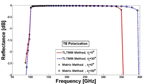
circularly polarized plane waves. The first layer is made of common lossy materials having a dispersion relation according to Eq. (4) and the second layer is composed of lossy MTMs with the dispersion relation in Eq. (6). The parameters of the layers are given in Table 1. The frequency response of a double layer DPS-MNG RAM under above conditions is shown in Fig. 2. It is observed that for frequencies from 1.2 to 18.6 GHz, the reflectance is less than 20 dB.
Figure 2. The reflectance of the DPS-MNG bilayer RAM coating composed of lossy common material and metamaterial under the plane wave incidence at incident angle of 30◦.
3.3. Dichroic Plate
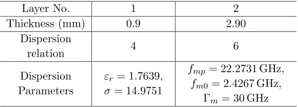
Table 1. Specification of the DPS-MNG bilayer RAM where the first layer is composed of common lossy materials with µr = 1 and the
second layer is composed of split ring resonators withεr= 1.
Layer No. 1 2
Thickness (mm) 0.9 2.90 Dispersion
relation 4 6
Dispersion Parameters
εr = 1.7639,
σ = 14.9751
fmp= 22.2731 GHz,
fm0 = 2.4267 GHz, Γm= 30 GHz
and less expensive, and having the required characteristics. A DNG dichroic plate is designed with εr in Eq. (5) and µr in Eq. (6),
and in the Ka frequency band. The plate thickness is obtained as 4.5 mm, the parameters of the dispersion relations are obtained: fep =
30.3679 GHz, fmp = 196.418 GHz, fm0 = 90 GHz, Γe = 11.930 GHz
and Γm = 1 MHz for the circularly polarized plane wave under the
incident angle of 30◦. The frequency responses of reflectance and transmittance of this dichroic plate are shown in Fig. 3. It is seen that in the frequency band 31.8–32.3 GHz, which is designed for reception, good reflection occurs, whereas in the band 34.2–34.7 GHz which is assigned for transmission, good transmission happens, and vice versa. These two frequency bands are used for the design of Mirror 7 of the deep space antenna of the European Space Agency installed in Spain [20].
3.4. Antenna Radome
permittivity is εr = 1 and its µr is assumed to obey the dispersion
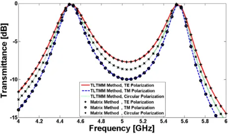
relation (6). The appropriate optimized parameters are obtained according to Table 2. The frequency response of its transmittance in the C band is shown in Fig. 4. The complete transmission about frequencies 4.5 and 5.5 GHz are seen in this figure.
Figure 3. The transmittance and reflectance frequency responses of a dichroic plate in theKa frequency band at incident angle of 30◦.
Figure 4. The transmittance-frequency dependence of a dual-band antenna radome in the C band at incident angle of 30◦.
3.5. Dual Band Reflectors MTM
Table 2. Specifications of a tri-layer radome which is composed of split ring resonator withεr= 1.
Layer No. 1 2 3
Thickness (mm) 5.5 0.7 1.1 fmp (GHz) 125 125 125
fm0 (GHz) 16.1244 7.9227 10.6441
Γm (MHz) 1 1 1
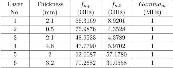
Fabrication of stealth wallpaper with MTM is a new application for MTM. For example a dual band reflector with six-layers of MNG-MTM is designed for the obstruction of data transmission at 2.4GHz and 3.4GHz. Fig. 5 shows the transmittance-frequency characteristic and Table 3 shows its designed parameters.
Figure 5. The transmittance-frequency dependence of a dual reflector inS band under TE polarization.
Table 3. Specifications of six-layers of MNG-MTM as a dual band reflector, composed of split ring resonators with εr = 1.
Layer No.
Thickness (mm)
fmp
(GHz)
fm0 (GHz)
Gammam
(MHz)
1 2.1 66.3169 8.9201 1
2 0.5 76.9876 4.3528 1
3 2.1 48.9533 4.3789 1
4 4.8 47.7790 5.9702 1
5 2 62.6087 57.1780 1
6 3.2 70.2682 31.0558 1
4. CONCLUSIONS
It is shown that the MTM multilayer structures act as FSS against the incident waves. The frequency responses of reflected and transmitted waves of such multilayer structures are accurately determined by a new transmission line transfer matrix method namely TLTMM and a matrix method, which demonstrate the dependence of their performance on the angle of incidence, polarization of the incident wave, physical parameters of the stratified media, and dispersion relations of materials.
Several new examples with novel applications were treated such as high reflection coatings, radar absorbing metamaterials, dichroic plates, antenna radomes and dual band reflector MTMs. The results of computations by TLTMM agree very well with other method. ACKNOWLEDGMENT
This research was in part supported by Iran Telecommunication Research Center under contract number 500/1911 dated 2007/5/8. REFERENCES
1. Mittra, R., C. H. Chan, and T. Cwik, “Techniques for analyzing frequency selective surfaces — A review,”Proceedings of the IEEE, Vol. 76, No. 12, 1593-1615, 1988.
3. Alu, A. and N. Engheta, “Pairing an epsilon-negative slab with a mu-negative slab: Resonance, tunneling and transparency,”IEEE Trans. on Antennas and Propagat., Vol. 51, No. 10, 2558–2571, 2003.
4. Caloz, C. and T. Itoh,Electromagnetic Metamaterials: Transmis-sion Line Theory and Microwave Applications, Wiley Interscience, 2006.
5. Kong, J. A., “Electromagnetic wave interaction with stratified negative isotropic media,”Progress In Electromagnetics Research, PIER 35, 1–52, 2002.
6. Qing, A. and C. K. Lee, “An improved model for full wave analysis of multilayered frequency selective surface with gridded square element,” Progress In Electromagnetics Research, PIER 30, 285– 303, 2001.
7. Cory, H. and C. Zach, “Wave propagation in metamaterial multi-layered structures,”Microwave Opt. Technol. Lett., Vol. 40, No. 6, 460–465, 2004.
8. Zhang, Y., T. M. Grzegorczyk, and J. A. Kong, “Propagation of electromagnetic waves in a slab with negative permittivity and negative permeability,” Progress In Electromagnetics Research, PIER 35, 271–286, 2001.
9. Oraizi, H. and M. Afsahi, “Determination of correct values for propagation constant, intrinsic impedance and refraction index of metamaterials,” IEEE Applied Electromagnetic Conference, AEMC, 1–4, Kolkata, India, 2007.
10. Oraizi, H. and M. Afsahi, “Determination of correct values for propagation constant, intrinsic impedance and refraction index of metamaterials,”IEEE Int. Conf. Applied Electromagnetic, Vol. 1, 1–4, India, 2007.
11. Pendry, J. B., A. J. Holden, W. J. Stewart, and I. Youngs, “Extremely low frequency plasmons in metallic mesostructures,” Phys. Rev. Lett., Vol. 76, No. 25, 4773–4776, 1996.
12. Pendry, J. B., A. J. Holden, D. J. Robbins, and W. J. Stewart, “Magnetism from conductors and enhanced nonlinear phenom-ena,” IEEE Trans. on Microwave Theory. Tech., Vol. 47, No. 18, 2075–2084, 1999.
13. Smith, D. R., W. J. Padilla, D. C. Vier, S. C. Nemat-Nasser, and S. Schultz, “Composite medium with simultaneously negative permeability and permittivity,”Phys. Rev. Lett., Vol. 84, No. 18, 4184–4187, 2000.
calculating the shielding effectiveness and light Transmittance of multilayered media,” IEEE Trans. Electrogagnetic Compatibility, Vol. 35, No. 4, 451–456, 1993.
15. Gerardin, J. and A. Lakhtakia, “Negative index of refraction and distributed Bragg reflectors,” Microwave and Optical Technology Letters, Vol. 34, No. 6, 409–411, 2002.
16. Knott, E. F., J. F. Shaeffer, and M. T. Tuley,Radar Cross Section, Artech House, London, 1993.
17. Mosallaei, H. and Y. Rahmat-Samii, “RCS reduction of canonical targets using genetic algorithm synthesized RAM,” IEEE Trans. on Antennas Propagat., Vol. 48, 1594–1606, 2000.
18. Mackay, A. J., “The theory and design of provably optimal bandwidth radar absorbent materials (RAM) using dispersive structures and/or frequency selective surfaces (FSS),”ICEAA Int. Conf. Electromagnetics in Advanced Applications, 3–8, Torino, Italy, 2007.
19. Terracher, F., G. Berginc, T.-C. Optronique, and R. Guyan-court, “Thin electromagnetic absorber using frequency selective surfaces,”IEEE Int. Conf. Antennas Propagat. Society, 846–849, Salt Lake, USA, 2000.
20. Besso, P., M. Bozzi, L. Perregrini, L. Salghetti Drioli, and W. Nickerson, “Deep space antenna for Rosetta mission: Design and testing of the S/X-band dichroic mirror,” IEEE Trans. on Antennas and Propagat., Vol. 51, No. 3, 388–394, 2003.
21. Besso, P., M. Bozzi, M. Formaggi, S. Germani, and L. Perregrini, “S/X/Ka-band dichroic mirrors for deep-space antennas,” IEEE Int. Symp. Antennas Propagat., Vol. 4, 372–375, 2005.
22. Bertoni, H., L.-H. Cheo, and T. Tamir, “Frequency-selective reflection and transmission by periodic dielectric layer,” IEEE Transactions on Antennas Propagat., Vol. AP-37, No. 1, 78–83, 1989.
23. Wu, T. K., Frequency Selective Surface and Grid Array, Wiley, New York, 1995.
24. Wu, T. K., “Cassini frequency selective surface development,” J. Electromagn. Waves Applicat., Vol. 8, No. 12, 1547–1561, 1994. 25. Romeu, J. and Y. Rahmat-Samii, “Fractal FSS: A novel dual-band