Abstract—Leaky-wave radiations are usually generated by leaking the electromagnetic energy gradually over a structure. By using the coupling effect and leaky-wave properties, this paper designs a novel 1-D frequency scanning antenna array. The antenna is intended for the direct imaging radar sensors. The simulated results show that the scanning angle can stay in the range from −60◦ to 30◦. The proposed 1-D antenna array was manufactured, and the measured results are consistent with the simulated ones.
1. INTRODUCTION
Searching a low-cost means to measure the distance and angle of targets is always a great challenge in the commercial radar sensors researches [1–3, 11–18]. In recent years, with the attractive advantages such as low profile, compact structure, wide frequency band, frequency beam scanning characteristics and easiness of integration with planar circuits, scientists and researchers have paid much attention to planar leaky-wave antennas (LWAs) [2–10]. By leaking electromagnetic energy along the structure, the radiated beams of LWAs can scan in the space as frequency changes [2]. Frequency beam scanning antennas are widely used in radar and wireless communication systems [3–5, 19].
In the design of frequency scanning antenna arrays, the range of scanning angle, the required frequency bandwidth, and the loss in the traveling-wave structure of the antenna should be considered. Typical frequency-scanning antenna arrays operate based on two basic mechanisms: one is the radiating function, and the other is the frequency-dependent phase shifter function [7, 13–17]. Because the phase adjustment can be realized through the change of frequency, the radiated beams can scan in the space as frequency changes [2].
In this paper, the propagation properties of the element of leaky-wave antenna are analyzed. The proposed antenna is fabricated and measured. The simulated results indicate that this printed antenna exhibits a good scanning performance of−60◦to 30◦with a maximum gain of 16.87 dBi, and the antenna has flat gain of more than simulated 13 dBi in the whole operation band from 8.3 GHz to 10.9 GHz. The measured results are consistent with simulated ones.
2. ELEMENT OF LEAKY-WAVE ANTENNA
In the antenna array design, the property of phase shifters is the main reason to realize beam scanning. In this paper, the phase adjustment is realized through the change of frequency. The proposed phase shifter is shown in Fig. 1. This phase shifter has dual functions: it can be used as phase shifter, and it can also leak electromagnetic waves and be used as radiating element. The increased coupling effect can contribute to increasing scanning angle. The proposed element has three layers. The top layer is a unit cell of LWAs. The middle layer is a substrate with permittivity of 2.65 and loss tangent of 0.001. The bottom layer is a metallic ground. The optimum dimensions are: h = 1.5 mm, l= 26 mm, w= 16.35 mm,p= 1 mm, a= 0.5 mm,ws= 0.75 mm,sg = 0.04 mm and g= 0.35 mm.
Received 26 March 2018, Accepted 10 July 2018, Scheduled 31 July 2018
* Corresponding author: Liaori Jidi ([email protected]).
(a) (b)
Figure 1. Proposed element of leaky-wave antenna, (a) topological view and (b) top view.
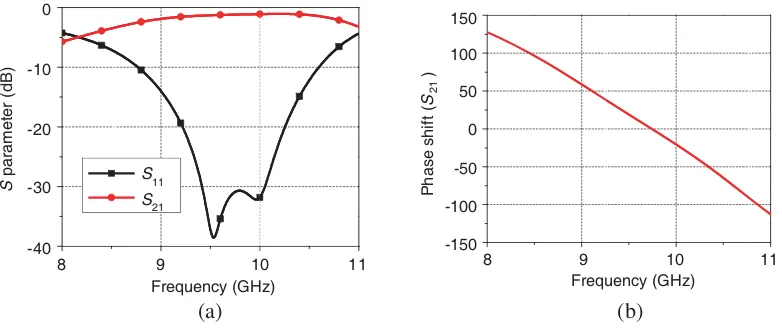
This phase shifter is simulated using HFSS, and its results are shown in Fig. 2. From Fig. 2, it can be seen that this element can radiate some electromagnetic power into space, and the phase shift from 8.3 GHz to 10.9 GHz is 215◦.
(a) (b)
8 9 10 11
Frequency (GHz)
8 9 10 11
Frequency (GHz) 0
-10
-20
-30
-40
S
parameter (dB)
150
100
50
0
-50
-100
-150
Phase shift (
S
)
21
S
S21
11
Figure 2. (a) Amplitude and (b) phase characteristics of the proposed element antenna design.
3. ANTENNA DESIGN
Based on the radiation element, we design a linear scanning antenna array, as shown in Fig. 3. This proposed linear scanning antenna array can radiate EM waves into free space element by element gradually, and each element also has a different phase shift as frequency changes, thus this proposed antenna can realize beam scanning. Using Ansoft HFSS, we also simulate this proposed 1-D linear array antenna, and its results are shown in Fig. 4. As expected, the radiated beams of this linear array antenna can scan in the space as frequency changes, and its scanning angle can stay in the range from −60◦ to 30◦.
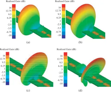
In order to make a better understanding of the beam scanning performance, the radiated far-field patterns of the proposed antenna array at different frequencies under polar coordinate system are illustrated in Fig. 5.
As shown in Fig. 5, it can be seen that the main beam of the proposed antenna array can point at different directions of the free space as frequency varies.
Figure 3. Proposed 1-D linear antenna array.
-60 -40 -20 0 20 40
Angle θ (degrees)
Figure 4. Simulated relative radiation pattern for the linear antenna array in E-plane.
(a) (b)
(c) (d)
16 12.75 9.5 6.25 3 -2.5 -3.5 -6.75 -10
Realized Gain (dB) Realized Gain (dB)
Realized Gain (dB) Realized Gain (dB) 16
12.75 9.5 6.25 3 -2.5 -3.5 -6.75 -10
16 12.75 9.5 6.25 3 -2.5 -3.5 -6.75 -10
16 12.75 9.5 6.25 3 -2.5 -3.5 -6.75 -10
Figure 5. Radiated far-field patterns of the proposed antenna array at (a) 8.6 GHz, (b) 9 GHz, (c) 10 GHz and (d) 10.9 GHz.
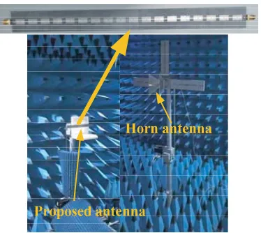
of antenna array, a matching load is loaded at the end of the array in the measurement process. The simulated and measured reflection and transmission coefficients are shown in Fig. 7. It can be seen from Fig. 7 that the measured results are in good agreement with the simulated ones. The simulated and measuredS11and S21are all less than−7.3 dB in the frequency band of 8.3–10.9 GHz. It indicates that
more than 82% electromagnetic energy is radiated into free space by the antenna elements. The S11
Figure 6. Fabricated sample and measurement environment.
(a) (b)
8.5 9.0 10.0 11.0
Frequency (GHz) 0
-10
-20
-30
S
(dB)
Measured S
Simulated S
21
11
-40
-50
11
9.5 10.5 8.5 9.0 10.0 11.0
Frequency (GHz)
9.5 10.5
11
Measured S
Simulated S21
0
-10
-20
-30
S
(dB) -40
-50
-60
-70
-80
21
Figure 7. Simulated and measured (a) reflection coefficients (S11) and (b) transmission coefficients
(S21) of proposed antenna array.
(a) (b)
0
-10
-20
-30
-40
Normalized radiation pattern (dB)
-60 -40 -20 0 20 40
Angle θ (degrees)
8.4 GHz 8.6 GHz
9 GHz 9.4 GHz
10.2 GHz 10.6 GHz
10.9 GHz -5
-15
-25
-35
9.8 GHz
10.8 GHz
8.5 9.0 10.0 11.0
Frequency (GHz)
9.5 10.5
Measured Simulated 20
15
10
5
Antenna Gain (dBi)
The measured results are in excellent agreement with the simulations.
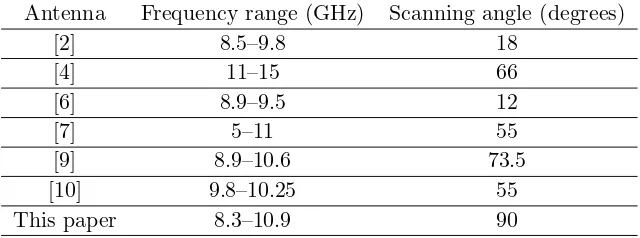
In order to clarify the effectiveness the antenna array in this paper, some similar beam-scanning antennas reported in the references are compared with the proposed antenna array in Table 1. It can be concluded that the proposed antenna array in this paper has a significantly wide scanning angle.
Table 1. Comparison of the proposed antenna with some similar works reported in references.
Antenna Frequency range (GHz) Scanning angle (degrees)
[2] 8.5–9.8 18
[4] 11–15 66
[6] 8.9–9.5 12
[7] 5–11 55
[9] 8.9–10.6 73.5
[10] 9.8–10.25 55
This paper 8.3–10.9 90
4. CONCLUSION
In this paper, a novel phase shifter is designed. This phase shifter has dual functions. It can be used as a phase shifter and radiated element. Based on the proposed element, we design a 1-D linear antenna array with the ability of wide scanning angle. In the operating frequency band of 8.3–10.9 GHz, the simulated scanning angle of the antenna array can stay in the range from−60◦to 30◦, while the measured scanning angle is from−62◦ to 29◦. The simulated gains of the antenna are more than 12.95 dBi, and the measured ones are more than 10.55 dBi. The measurements are in good agreement with simulations. Because of the wide beam-scanning ability, easiness of design and low cost in fabrication, the proposed antenna array has potential applications in radar and wireless communication systems.
ACKNOWLEDGMENT
This work is supported by the National Natural Science Foundation of China (No. 61271100, No. 61471389, No. 61671464 and No. 61501494). Authors also thank reviewers for their valuable comments.
REFERENCES
1. Cameron, T. R. and G. V. Eleftheriades, “Experimental validation of a wideband metasurface for wide-angle scanning leaky-wave antennas,” IEEE Trans. Antennas Propag., Vol. 65, No. 10, 5245, 2017, ISSN: 0018-926X, doi: 10.1109/TAP.2017.2735454.
3. Xu, J. J., H. C. Zhang, Q. Zhang, and T. J. Cui, “Efficient conversion of surface-plasmon-like modes to spatial radiated modes,” Appl. Phys. Lett., Vol. 106, No. 021102, 1, 2015, doi: org/10.1063/1.4905580.
4. Guan, D. F., P. You, Q. F. Zhang, Z. H. Lu, S. W. Yong, and K. Xiao, “A wide-angle and circularly polarized beam-scanning antenna based on microstrip spoof surface plasmon polariton transmission line,” IEEE Antennas Wireless Propag. Lett., Vol. 16, 2538, 2017, ISSN: 1536-1225, doi: 10.1109/LAWP.2017.2731877.
5. Yang, G. W., J. Y. Li, S. G. Zhou, and Y. X. Qi, “A wide-angle e-plane scanning linear array antenna with wide beam elements,” IEEE Antennas Wireless Propag. Lett., Vol. 16, 2923, 2017, ISSN: 1536-1225, doi: 10.1109/LAWP.2017.2752713.
6. Liu, X. B., B. Chen, J. S. Zhang, W. Li, J. Chen, A. X. Zhang, and H. Y. Shi, “Frequency-scanning planar antenna based on spoof surface plasmon polariton,”IEEE Antennas Wireless Propag. Lett., Vol. 16, 165, 2017, ISSN: 1536-1225, doi: 10.1109/LAWP.2016.2565603.
7. Yin, J. Y., J. Ren, Q. Zhang, et al., “Frequency-controlled broad-angle beam scanning of patch array fed by spoof surface plasmon polaritons,” IEEE Trans. Antennas Propag., Vol. 64, No. 12, 5181, 2016, ISSN: 0018-926X, doi: 10.1109/TAP.2016.2623663.
8. Wang, J. F., S. B. Qu, H. Ma, et al., “High-efficiency spoof plasmonpolariton coupler mediated by gradient metasurfaces,” Appl. Phys. Lett., Vol. 101, No. 201104, 1, 2012, doi: org/10.1063/1.4767219.
9. Cui, L., W. Wu, and D. G. Fang, “Printed frequency beam-scanning antenna with flat gain and low side lobe levels,” IEEE Antennas Wireless Propag. Lett., Vol. 12, 292, 2013, ISSN: 1536-1225, doi: 10.1109/LAWP.2013.2248696.
10. Boskovic, N., B. Jokanovic, and M. Radovanovic, “Printed frequency scanning antenna arrays with enhanced frequency sensitivity and sidelobe suppression,”IEEE Trans. Antennas Propag., Vol. 65, No. 4, 1757, 2017, ISSN: 0018-926X, doi: 10.1109/TAP.2017.2670528.
11. Sun, S. L., K. Y. Yang, C. M. Wang, et al., “High-efficiency broadband anomalous reflection by gradient meta-surfaces,”Nano Letters, Vol. 12, 6223, 2012, doi:org/10.1021/nl3032668.
12. Zheng, Q. Q., Y. F. Li, J. Q. Zhang, et al., “Wideband, wide-angle coding phase gradient metasurfaces based on Pancharatnam-Berry phase,”Scientific Reports, Vol. 7, No. 43543, 1, 2017, doi: 10.1038/srep43543.
13. Lianinejad, A., Z. N. Chen, and C. W. Qiu, “A single-layered spoof-plasmon-mode leaky wave antenna with consistent gain,” IEEE Trans. Antennas Propag., Vol. 65, No. 2, 681, 2017, ISSN: 0018-926X, doi: 10.1109/TAP.2016.2633161.
14. Shen, X. P., T. J. Cui, D. Martin-Cano, and F. J. Garcia-Vidal, “Conformal surface plasmons propagating on ultrathin and flexible films,” Pans, Vol. 110, No. 1, 40, 2013, doi:10.1073/pnas.1210417110.
15. Darvazehban, A., Q. Manoochehri, et al., “Ultra-wideband scanning antenna array with Rotman lens,” IEEE Transactions on Microwave Theory and Techniques, Vol. 65, No. 9, 3435, 2017, ISSN:0018-9480, doi:10.1109/TMTT.2017.2666810.
16. Katyal, A. and A. Basu, “Compact and broadband stacked microstrip patch antenna for target scanning applications,”IEEE Antennas Wireless Propag. Lett., Vol. 16, 381, 2017, ISSN:1536-1225, doi:10.1109/LAWP.2016.2578723.
17. Prasad, C. S. and A. Biswas, “Dielectric image line-based leaky-wave antenna for wide range of beam scanning through broadside,” IEEE Trans. Antennas Propag., Vol. 65, No. 8, 4311, 2017, ISSN:0018-926X, doi:10.1109/TAP.2017.2714024.
18. Cao, W. Q., Z. N. Chen, W. Hong, et al., “A beam scanning leaky-wave slot antenna with enhanced scanning angle range and flat gain characteristic using composite phase-shifting transmission line,” IEEE Trans. Antennas Propag., Vol. 62, No. 11, 5871, 2014, ISSN:0018-926X, doi:10.1109/TAP.2014.2350512.