Available online: https://edupediapublications.org/journals/index.php/IJR/ P a g e | 2516
Ac Dynamic Load Control from Solar Energy by Using
Phase In-Position Control Technique
Manikonda Raju & Mrs.A.Chitraleka
1M.Tech(Student), Vaagdevi College of Engineering(Autanomous), Warangal, Telangana, India. 2Assistant professor, Vaagdevi College of Engineering(Autanomous), Warangal, Telangana, India.
Abstract- A two stage, three-phase grid interfaced SPV (Solar Photovoltaic) energy conversion system with an ANF (Adaptive Notch Filter) based control algorithm is proposed in this paper. In this paper we are using in phase opposition technique. In this technique the carrier pulses arranged in a linear and in phase with overlapping manner to get both positive and negative sequence. The ANF has been used for extraction of fundamental part of load current. The proposed system uses an adaptive notch filter based control algorithm, which is proposed and comparatively more suitable for non-stationary environment. The proposed SPV system is a multi-function grid-interfaced solar PV energy conversion system, which along with conversion of dc-power from SPV to ac mains, is capable of reactive power compensation, harmonics currents elimination and load balancing in a three-phase ac distribution system. A multifunction grid-interfaced SPV energy conversion system is capable to capital investment, space and maintenance cost on behalf of multifunctional features compared to multiple devices with different functionalities. Compared to other methods the control algorithm is adaptive with respect to the fundamental frequency of the system and provides instantaneous values of the fundamental signals. The advantages of this technique the switching losses will be decreased and efficiency will be increased. By using the simulation results we can verify the validity of the presented algorithm and confirms its desirable transient and steady state performances.
Index Terms— Solar photovoltaic, harmonics elimination, MPPT, Power quality and load balancing.
INTRODUCTION
Solar photovoltaic (PV) energy conversion system has shown increase at a moderate annual rate of 60% in the last five years [1]. This is possible because of alternate clean energy sources, reduction of cost, efficiency increase of PV modules and subsidy scheme of political regulations. SPV (Solar Photovoltaic) energy conversion systems are gaining momentum due to suitable government policies, falling prices and increased research in the area. Solar PV energy conversion systems can be of two types: standalone and grid-interfaced power generating systems. Standalone systems require additional energy storage device for reliable and efficient operation but energy storage devices like batteries increase both capital and maintenance cost of the system. Grid-interfaced solar energy conversion
systems do not require storage device. An integration of any renewable energy source to the electric grid has to fulfill standard power quality requirements so that the grid is not polluted due to such interface [1-5].
To overcome the power quality problems various custom power devices provided. Such as, shunt, series, hybrid and shunt-series connected devices for power quality improvement are proposed. The proposed system is a multi-function device. A three-phase single stage multifunctional SPV system is proposed. In this paper, a two stage three-phase SPV energy conversion system is proposed using a three-leg VSC (Voltage Source Converter). The ANF successfully extracts a single sinusoid of a possibly non-stationary nature from harmonics corrupted load currents at PCC (Point of Common Coupling).
1. The use of ANF based control approach to overcome the drawbacks of SRFT, which enables fast dynamic response along with good steady state accuracy.
2. The use of PV feed-forward terms in the control loop for fast dynamic responses under variation in climatic condition. The proposed solar PV energy conversion system has been simulated. A wide variety of results are shown to demonstrate all the features of the proposed system.
The proposed two-stage circuit configuration for this purpose provides greater flexibility and better capacity utilization of VSC as compared to single-stage case, wherein the VSC is kept overrated considering variation of voltage of SPV array with respect to insulation and temperature. Fast dynamic response, easy implementation and robustness due simple mathematical functions are the main advantages of the proposed ANF based control algorithm.
SYSTEM CONFIGURATION
Available online: https://edupediapublications.org/journals/index.php/IJR/ P a g e | 2517
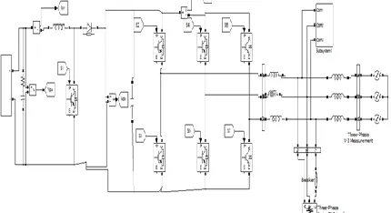
The PV array is connected at input of boost converter. The boost converter performs the functions of electrical MPPT (Maximum Power Point Tracking) and boosts the array voltage to 700V while feeding power to the dc link.
Fig. 1 system configuration.
In second stage, a three-leg VSC is used for interfacing the dc link with the ac supply system. This VSC performs the functions of converting dc power to suitable ac voltages, load balancing, harmonics current elimination and reactive power compensation. Filter inductors are used to reduce ripple currents in the VSC.
PV SOURCE
Photovoltaics (PV) covers the conversion of light into electricity using semiconducting materials that exhibit the photovoltaic effect, a phenomenon studied in physics, photochemistry, and electrochemistry. The dynamic model of PV cell is shown in below Fig.2.
Fig 2.Equivalent electrical circuit of the PV cell. The basic equation describing the I -V characteristic of a practical PV cell is
I = IL− Id− Ish = IL− ID e
Q V oc
AKT −1 −Vout+IRS
RSh (1)
where I D is the saturation current of the diode, Q is the electron charge, A is the curve fitting constant (or diode emission factor), K is the Boltzmann
constant and T is the temperature on absolute scale. PV systems convert light directly into electricity and shouldn't be confused with other technologies, such as concentrated solar power or solar thermal, used for heating and cooling.
CONTROL ALGORITHM
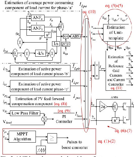
Fig. 3 shows the block diagram of proposed adaptive notch filter based control algorithm. In this algorithm, phase PCC voltages (vsa, vsb, vsc), grid currents (isa, isb isc), load currents (iLa, iLb, iLc), dc-link voltage (vdc), PV-array voltage (vpv) and PV-array current (ipv) are required for the estimation of reference grid currents (isa*, isb*, isc*).
Fig.3 ANF based control algorithm of a two-stage, three-phase grid interfaced SPV system.
The reference grid currents are further used for generation of switching logic. Mathematical and logical expressions for formulation of proposed control algorithm are given in the following section. In this method, PV array voltage and current are sensed and are fed to the controller in which change in sensed PV voltage and PV current is calculated as,
𝑑𝑉𝑃𝑉= 𝑉𝑃𝑉 𝑘 − 𝑉𝑃𝑉 𝑘 − 1 , 𝑑𝐼𝑃𝑉 = 𝐼𝑃𝑉 𝑘 − 𝐼𝑃𝑉 𝑘 − 1 (2)
Available online: https://edupediapublications.org/journals/index.php/IJR/ P a g e | 2518
𝑉𝑝𝑣𝑟𝑒𝑓 𝑘 =
𝑉𝑝𝑣𝑟𝑒𝑓 𝑘−1 𝑖𝑓 𝑑𝑉𝑃𝑉≠0 𝑎𝑛𝑑 𝑑𝐼𝑃𝑉 𝑑𝑉𝑃𝑉 =− 𝐼𝑃𝑉 𝑉𝑃𝑉
𝑉𝑝𝑣𝑟𝑒𝑓 𝑘−1 +𝑠𝑡𝑒𝑝 𝑖𝑓 𝑑𝑉𝑃𝑉≠0 𝑎𝑛𝑑 𝑑𝐼𝑃𝑉 𝑑𝑉𝑃𝑉 >− 𝐼𝑃𝑉 𝑉𝑃𝑉
𝑉𝑝𝑣𝑟𝑒𝑓 𝑘−1 −𝑠𝑡𝑒𝑝 𝑖𝑓 𝑑𝑉𝑃𝑉≠0 𝑎𝑛𝑑 𝑑𝐼𝑃𝑉 𝑑𝑉𝑃𝑉 <− 𝐼𝑃𝑉 𝑉𝑃𝑉
𝑉𝑝𝑣𝑟𝑒𝑓 𝑘−1 −𝑠𝑡𝑒 𝑝 𝑖𝑓 𝑑𝑉𝑃𝑉=0 𝑎𝑛𝑑 𝑑𝐼𝑝𝑣<0
𝑉𝑝𝑣𝑟𝑒𝑓 𝑘−1 +𝑠𝑡𝑒𝑝 𝑖𝑓 𝑑𝑉𝑃𝑉=0 𝑎𝑛𝑑 𝑑𝐼𝑝𝑣>0
𝑉𝑝𝑣𝑟𝑒𝑓 𝑘−1 𝑖𝑓 𝑑𝑉𝑃𝑉=0 𝑎𝑛𝑑 𝑑𝐼𝑝𝑣=0
(3) This Vpvref(k) is used to determine a suitable duty cycle for the boost converter used as 1st stage. This duty cycle is used to generate the pulse for the boost converter. The amplitude of three-phase PCC voltages is estimated using PCC phase voltages (vsa, vsb, and vsc). The expression for amplitude estimation is as,
𝑉𝑡 = 2 𝑣𝑠𝑎2+𝑣𝑠𝑏2+𝑣𝑠𝑐2
3 (4)
So, the in-phase unit templates (uap, ubp, ucp) can be estimated using, 𝑢𝑎𝑝 =𝑣𝑠𝑎 𝑉𝑡 , 𝑢𝑏𝑝 = 𝑣𝑠𝑏 𝑉𝑡 , 𝑢𝑐𝑝 = 𝑣𝑠𝑐
𝑉𝑡 (5)
And the quadrature unit templates (uaq, ubq, ucq) can be generated as,
𝑢𝑎𝑝 =−𝑢𝑏𝑝+𝑢𝑐𝑝
3 , 𝑢𝑏𝑞 =
3𝑢𝑎𝑝+𝑢𝑏𝑝−𝑢𝑐𝑝
2 3 , 𝑢𝑐𝑞 =
−3𝑢𝑎𝑝+𝑢𝑏𝑝−𝑢𝑐𝑝
2 3 (6)
The load current mainly consists of fundamental, harmonics and dc components. The fundamental portion of load current can be further divided into current in-phase and 90° shifted with respect to respective phase voltage. An adaptive theory based notch filter with adaptive frequency is used to estimate the fundamental part of load current of phase “a”(iLfa), as shown in the block diagram of Fig. 3.
An adaptive notch filter (ANF) based control technique is used to estimate average power consuming component of load current. In conventional notch filter, the notch frequency is kept constant whereas in case of ANF, the grid frequency is estimated and notch is placed at estimated grid frequency (θ). For nth order harmonic, the notch frequency is nθ. The dynamic equations for notch filter for nth order harmonic are as,
𝑥𝑛+ 𝑛2𝜃2𝑥
𝑛 = 2𝛼𝜃𝑒𝑡 (7) 𝜃 = −𝐾𝑥1𝜃𝑒𝑡 (8)
where α and K are positive real numbers which decide accuracy and convergence speed. The estimation of frequency is a first order differential equation and ANF is characterized by second order differential equation.
The output of ANF1 is fundamental frequency component of input signal in phase with input signal. The amplitudes of average power
consuming component of load currents (Ifpa, Ifpb and I fcp) are extracted by taking absolute value of fundamental load currents at the positive and negative hit crossings of quadrature-phase unit template (uqa) of PCC voltages. The input signal of SH (fundamental load current) is then sampled and hold at every zero crossing of uaq. The instantaneous compensation term for solar PV power is given as,
𝐼𝑝𝑣𝑎 =2∗𝑃𝑝𝑣
𝑉𝑡 (9)
A PI (Proportional Integral) controller is used to keep the dc link voltage at the set reference value. The error between the sensed and reference dc link voltages is given to PI controller. The output of which denotes the loss component or current needed to maintain the dc link voltage to reference value. The governing equations in discrete domain is as,
𝐼𝑙𝑜𝑠𝑠 𝑘 = 𝐼𝑙𝑜𝑠𝑠 𝑘 − 1 + 𝐾𝑝 𝑉𝑑𝑐𝑒𝑟𝑟𝑜𝑟 𝑘 − 𝑉𝑑𝑐𝑒𝑟𝑟𝑜𝑟𝑘−1+𝐾𝑖𝑣𝑑𝑐𝑒𝑟𝑟𝑜𝑟𝑘 (10) where Iloss is output loss component from PI controller, Kp is proportional gain. Ki is integral gain and vdcerror is error the sensed and reference dc link voltage. The net average power-consuming component of current to be extracted from the grid is estimated as,
𝐼𝑝𝑛𝑒𝑡 = 𝐼𝐿𝑝𝑎 + 𝐼𝐿𝑝𝑏 + 𝐼𝐿𝑝𝑐 − 𝐼𝑝𝑣𝑎 + 𝐼𝑙𝑜𝑠𝑠 (11) For balanced grid currents in all three phases the Ipnet is divided by 3 and reference grid currents are given as,
𝑖𝑠𝑎∗ = 𝐼𝑝𝑛𝑒𝑡
3 ∗ 𝑢𝑝𝑎, 𝑖𝑠𝑏 ∗ =𝐼𝑝𝑛𝑒𝑡
3 ∗ 𝑢𝑝𝑏, 𝑖𝑠𝑐
∗ =
𝐼𝑝𝑛𝑒𝑡
3 ∗ 𝑢𝑝𝑐 (12)
These reference currents so derived are compared with sensed grid currents and a hysteresis current controller is used for inner current control loop.
MATLAB MODELING AND SIMULATION RESULTS
A two-stage, grid interfaced SPV energy conversion system using three-leg VSC is designed The performance of the system is simulated under various operating conditions
Available online: https://edupediapublications.org/journals/index.php/IJR/ P a g e | 2519
Fig. 5 ANF based control algorithm of a two-stage, three-phase grid interfaced SPV system
Fig:6.MPPT algorithm Phase in-position technique
In this technique, the carrier pulses are arranged in a linear and in-phase with overlapping manner to get both positive and negative sequence. These ramp pulses or carrier pulses compared with reference pulses i.e. sinusoidal wave to get switching signals for every level in the multi-level inverter.
Fig.7 Phase in phase opposition technique By using this technique, the switching losses will be decreased and efficiency will be increased. Because each carrier wave includes all the levels of both positive and negative sequence in the multi-level inverter.
Simulated Behavior under Linear Load
Conditions
A linear load of 25 kW, 0.8 lagging power factor is connected to the proposed system.
Performance of the system for a period of 0.35s to 0.5s is shown in Fig. 8.
Fig.8.Simulated performance under linear load conditions.
Simulated Behavior under Nonlinear Load Conditions
Available online: https://edupediapublications.org/journals/index.php/IJR/ P a g e | 2520
Fig.9.Simulated performance under nonlinear load conditions.
The effective load after disconnection of phase-c is a single-phase diode bridge rectifier connected between line to line of ac supply system. The load currents after disconnection seem linear as the inductor on the dc side is not sufficient to keep constant current after load disconnection. Under these operating conditions, the grid currents are maintained balanced and at unity power factor w.r.t. grid voltages.
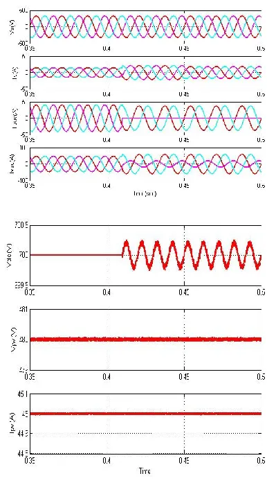
Simulated Behavior under Sudden Variation of Solar Insolation Level
In this case, a balanced linear load of 25 kW, 0.8 lagging power factor is connected across the PCC. The solar irradiance level is suddenly varied from the 1000W/m2 to 500W/m2 as shown in Fig. 10. With sudden drop in the insolation, PV current decreases as solar PV array is primarily an insolation dependent current source. With decrease in PV current, the power supplied by PV array also decreases.
Fig.10. Simulated performance under change in solar insolation level.
CONCLUSION
A two-stage system has been proposed for three-phase grid connected solar PV generation. The design, control, simulation and implementation of multifunctional, two-stage, three-phase SPV energy conversion system have been analyzed using an control algorithm based on ANF. In this paper phase in phase opposition technique, the switching losses will be decreased and efficiency will be increased. Because each carrier wave includes all the levels of both positive and negative sequence in the multi-level inverter. The ANF has been used for extraction of fundamental part of load current. For harmonics elimination, compensation of reactive power, load balancing and power factor correction the performance of the system has been demonstrated. An InCA technique has been used for the electrical MPPT of SPV panels. The performance of the two-stage, three-phase grid-interfaced SPV energy system has been found satisfactory under different dynamics and steady state operating conditions. By using the simulation results we can analyze the feasibility of the control method.
REFERENCES
[1] N. Jain, S. N. Singh and S.C. Srivastava, “A Generalized Approach for DG Planning and Viability Analysis Under Market Scenario,” IEEE Transactions on Industrial Electronics, vol. 60, no. 11, pp. 5075-5085, Nov. 2013.
Available online: https://edupediapublications.org/journals/index.php/IJR/ P a g e | 2521
Industrial Electronic, vol. 60, no. 5, pp.1810-1818, May 2013.
[3] D. Espinoza, E. Barcenas, D. Campos-Delgado and C. De Angelo, “Voltage-Oriented Input-Output Linearization Controller as Maximum Power Point Tracking Technique for Photovoltaic Systems,” IEEE Transactions on Industrial Electronics, Early access. [4] IEEE Recommended Practices and requirement for Harmonic Control on Electric Power System, IEEE Std. 519, 1992.
[5] Byunggyu Yu, Mikihiko Matsui and Gwonjong Yu “A review of current anti-islanding methods for photovoltaic power system,” Solar Energy, vol. 84, pp. 745-754, 2010. [6] Antonio Moreno Munoz, Power Quality: Mitigation Technologies in a Distributed Environment, Springer-Verlag, London, 2007.
[7] M.S. Hamad, M.I. Masoud, K.H. Ahmed and B.W. Williams, “A Shunt Active Power Filter for a Medium-Voltage 12-Pulse Current Source Converter Using Open Loop Control Compensation,” IEEE Transactions on Industrial Electronics, vol. 61, no. 11, pp. 5840-5850, Nov. 2014.
[8] J.D. Barros and J.F. Silva, “Multilevel Optimal Predictive Dynamic Voltage Restorer," IEEE Transactions on Industrial Electronics, vol. 57, no. 8, pp. 2747-2760, Aug. 2010.
[9] C. Kumar and M.K. Mishra, “An Improved Hybrid DSTATCOM Topology to Compensate reactive and Nonlinear Loads,” IEEE Transactions on Industrial Electronics, vol. 61, no. 12, pp. 6517-6527, Dec. 2014.
[10] B.W. Franca, L.F. da Silva, M.A. Aredes and M. Aredes, “An Improved iUPQC Controller to Provide Additional Grid-Voltage Regulation as a STATCOM,” IEEE Transactions on Industrial Electronics, Early access.