University of South Carolina
Scholar Commons
Theses and Dissertations
2015
Design and Development of a Ventilation
Chamber for Testing Efficacy of Tracheal Stents
Caroline N. Horton University of South Carolina
Follow this and additional works at:https://scholarcommons.sc.edu/etd
Part of theBiomedical Engineering and Bioengineering Commons
This Open Access Thesis is brought to you by Scholar Commons. It has been accepted for inclusion in Theses and Dissertations by an authorized Recommended Citation
Design and Development of a Ventilation Chamber for Testing Efficacy of Tracheal Stents
By
Caroline N. Horton
Bachelor of Science
University of South Carolina, 2013
____________________________________________________________
Submitted in Partial Fulfillment of the Requirements
For the Degree of Master of Science in
Biomedical Engineering
College of Engineering and Computing
University of South Carolina
2015
Accepted by:
David N. Rocheleau, Director of Thesis
M. Damon Kolok, Reader
Acknowledgements
I would like to first thank Dr. David Rocheleau for his continued guidance and patience
with me as I struggled to design a chamber worthy of this degree. I know that there were
many times I felt like giving up, but Dr. Rocheleau found a way for me to push forward.
In addition, I would like to thank Dr.’s Franklin McGuire, Damon Kolok, and Maria Del
Mar Cirino, for providing their expertise and guidance as related to the field of
pulmonology. This work was developed due to a need that they felt should be addressed,
and without their insight, this project would have never begun.
I am very grateful for the help I’ve received from Mike Gore and Burt Ward in the School
of Medicine and Mechanical Engineering Machine Shops, as both were incredibly helpful
in converting my rough sketches to viable chamber options, and provided valuable input
for the best design.
Also, the efforts of my fellow researchers on this project, Zach Schwab and Nidah Hussain,
have not gone unnoticed. Zach’s help in particular was instrumental in testing of the
designs, as I often used him as the muscle behind the pumps. I am also very grateful to my
friends and family for putting up with me and even providing advice. Specifically, my
Abstract
Tracheobronchial malacia results in a weakening of the tracheal walls, leading to
increased difficulty breathing. Stents are used to reopen the lumen of the trachea, however,
current models are not personalized to each patient, leading to migration, inflammation,
and breakage of the stents. In order to successfully test novel stent designs, a ventilation
chamber is needed to recreate the breathing conditions of the body.
The following describes the iterative development of a ventilation chamber, which
allows inflation and deflation of lungs via negative pressure ventilation, as representative
of an actual body undergoing respiration. Previous work shows that lungs are not generally
used as the testing medium, as only excised portions of trachea are used. The chamber
presented here would allow testing to the primary and secondary bronchi, which is
beneficial to medical practitioners. This chamber would be utilized for simulating an in
vivo environment, in which, tracheal and bronchial stents may be tested and analyzed. The
chamber described is of simple, replicative design, with attachment of a bladder acting as
a diaphragm, which is expanded and reduced to recreate representative pressures of the
chest cavity. A trachea and lungs, porcine in nature for testing purposes, are attached at the
opposite end of the chamber, via a conduit allowing them to remain open to atmosphere,
allowing the lungs to inflate via negative pressure.
Table of Contents
Acknowledgements ... iii
Abstract ... iv
List of Figures ... vii
List of Tables ... xi
Chapter 1: Literature Review of Existing Pulmonary Stent Designs, Inflammatory Response, and Current Chamber Designs ...1
1.1 Existing Pulmonary Stents ...1
1.2 Animal Testing ...6
1.3 Existing Lung Chambers ...11
1.4 Stent Customization ...15
Chapter 2: Design Development ...17
2.1 Dismissal of Need for Tissue Fixation ...19
2.2 Proof of Concept and Material Selection ...20
2.3 Evaluation of Early Design Concepts ...22
2.4 Choosing a Diaphragm ...27
2.5 Pressure Monitoring ...29
Chapter 3: Design Prototypes ...31
3.1 Final Prototype Design and Testing Method ...34
Chapter 4: Testing Procedures ...37
4.2 Chamber Testing Methodology ...38
Chapter 5: Evaluation of Prototypes ...41
5.1 Results of Human Subjects ...42
5.2 Porcine Lung Testing ...46
Chapter 6: Pump Selection...55
6.1 Proposed Solution for Future Work ...56
Chapter 7: Conclusions ...58
Bibliography ...62
Appendix A: Patented Chamber Diagrams ... 65
Appendix B: Equations Used to Estimate Tidal Volume ... 67
Appendix C: Figures Pertaining to Human Ventilation Trials ... 68
Appendix D: Statistical Analysis of Human Trials... 73
Appendix E: Figures Pertaining to Unrestricted Porcine Lung Ventilation Trials ... 81
Appendix F: Statistical Analysis of Unrestricted Porcine Lung Trials ... 84
Appendix G: Figures Pertaining to Restricted Porcine Lung Ventilation Trials ... 87
List of Figures
Figure 1.1. Overview of currently available stents ...3
Figure 1.2. Examples of Freitag stent, in three different sizes ...4
Figure 1.3. Shape profile of trachea ...6
Figure 1.4. Branching angles at the carina from the main bronchus ...6
Figure 2.1. Schematic of design constraints ...19
Figure 2.2. Ventilation Chamber Concept 1 ...23
Figure 2.3. Ventilation Chamber Concept 2 ...24
Figure 2.4. Ventilation Chamber Concept 3 ...25
Figure 2.5. Ventilation Chamber Concept 4 ...26
Figure 2.6. Two tube bladder used as diaphragm substitute ...28
Figure 3.1. Image of Prototype 1 ...31
Figure 3.2. Image of Prototype 2 ...32
Figure 3.3. Prototype 3: Final Chamber Design ...35
Figure 5.1. Representative charts of total flow (L) for quiet breathing of six subjects ...44
Figure 5.2. Flow rate of lungs in Prototype 2 ...47
Figure 5.3. Total flow into and out of lungs in Prototype 2...47
Figure 5.4. Trial 3 of unobstructed large lung in Prototype 3...48
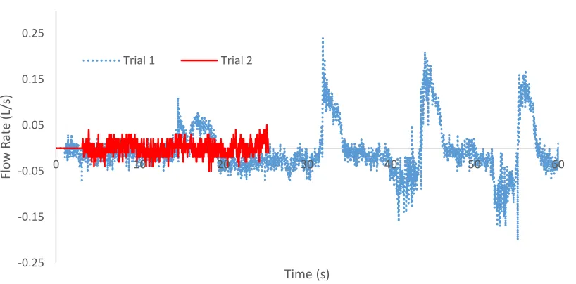
Figure 5.5. Trial 1 of unobstructed smaller lung in Prototype 3 ...49
Figure 5.7. Trachea with 3D printed stent inserted to cause reduction by 30% ...52
Figure 5.8. Reduction in magnitude of flow due to insertion of 3D printed stent designed with 30% reduction of inner diameter ...53
Figure 6.1. Airhead® high volume bellows pump ...56
Figure A.1. Chamber design by Burt Orden, US Patent 4,167,070 (1979) ...65
Figure A.2. Chamber design by Estetter et al., US Patent 6,874,501 B1 (2005) ...66
Figure C.1. F1 graphical representation of total flow and flow rate for Trial 1 ...68
Figure C.2. F1 graphical representation of total flow and flow rate for Trial 2 ...68
Figure C.3. F1 graphical representation of total flow and flow rate for Trial 3 ...68
Figure C.4. F2 graphical representation of total flow and flow rate for Trial 1 ...69
Figure C.5. F2 graphical representation of total flow and flow rate for Trial 2 ...69
Figure C.6. F2 graphical representation of total flow and flow rate for Trial 3 ...69
Figure C.7. F3 graphical representation of total flow and flow rate for Trial 1 ...69
Figure C.8. F3 graphical representation of total flow and flow rate for Trial 2 ...70
Figure C.9. F3 graphical representation of total flow and flow rate for Trial 3 ...70
Figure C.10. M1 graphical representation of total flow and flow rate for Trial 1 ...70
Figure C.11. M1 graphical representation of total flow and flow rate for Trial 2 ...70
Figure C.12. M1 graphical representation of total flow and flow rate for Trial 3 ...71
Figure C.13. M2 graphical representation of total flow and flow rate for Trial 1 ...71
Figure C.14. M2 graphical representation of total flow and flow rate for Trial 2 ...71
Figure C.15. M2 graphical representation of total flow and flow rate for Trial 3 ...71
Figure C.16. M3 graphical representation of total flow and flow rate for Trial 1 ...72
Figure E.1. Graphical representation of total flow and flow rate for Trial 1 of
lung taken from 200-300 lb pig ...81
Figure E.2. Graphical representation of total flow and flow rate for Trial 2 of
lung taken from 200-300 lb pig ...81
Figure E.3. Graphical representation of total flow and flow rate for Trial 3 of
lung taken from 200-300 lb pig ...81
Figure E.4. Graphical representation of total flow and flow rate for Trial 1 of
lung taken from 170 lb pig ...82
Figure E.5. Graphical representation of total flow and flow rate for Trial 2 of
lung taken from 170 lb pig ...82
Figure E.6. Graphical representation of total flow and flow rate for Trial 3 of
lung taken from 170 lb pig ...82
Figure E.7. Graphical representation of total flow and flow rate for Trial 1 of
lung taken from 170 lb pig with 3D printed open stent in place ...83
Figure E.8. Graphical representation of total flow and flow rate for Trial 2 of
lung taken from 170 lb pig with 3D printed open stent in place ...83
Figure E.9. Graphical representation of total flow and flow rate for Trial 3 of
lung taken from 170 lb pig with 3D printed open stent in place ...83
Figure G.1. Graphical representation of total flow for Trial 1 of lung taken
from 170 lb pig with hose clamp causing 30% restriction to outer diameter
of trachea ...87
Figure G.2. Graphical representation of total flow for Trial 2 of lung taken
from 170 lb pig with hose clamp causing 30% restriction to outer diameter
of trachea ...87
Figure G.3. Graphical representation of total flow for Trial 3 of lung taken
from 170 lb pig with hose clamp causing 30% restriction to outer diameter
of trachea ...87
Figure G.4. Graphical representation of total flow for Trial 1 of lung taken from 170 lb pig with 3D printed stent causing 30% restriction to inner
diameter of trachea ...88
Figure G.5. Graphical representation of total flow for Trial 2 of lung taken from 170 lb pig with 3D printed stent causing 30% restriction to inner
Figure G.6. Graphical representation of total flow for Trial 3 of lung taken from 170 lb pig with 3D printed stent causing 30% restriction to inner
List of Tables
Table 3.1 Inner dimensions of prototypes in relation to average lung size ...34
Table 5.1. Ideal body weight and tidal volume range estimation of six volunteer subjects...43
Table 5.2. Trial comparison p-values of each subject ...45
Table 5.3. Trial comparison p-values of porcine lungs ...49
Table 7.1. Average breaths per minute (BPM) and calculated tidal volume (TV) for human and Prototype 3 testing. ...60
Table B.1. Comparison of ideal body weight equations for men and women (Shah et al. 2006) ...67
Table D.1. ANOVA analysis of tidal volumes obtained from F1 ...73
Table D.2. T-Test comparison between Trial 1 and 2 of F1 ...73
Table D.3. T-Test comparison between Trial 1 and 3 of F1 ...74
Table D.4. T-Test comparison between Trial 2 and 3 of F1 ...74
Table D.5. ANOVA analysis of tidal volumes obtained from F2 ...75
Table D.6. ANOVA analysis of tidal volumes obtained from F3 ...75
Table D.7. ANOVA analysis of tidal volumes obtained from M1 ...76
Table D.8. T-Test comparison between Trial 1 and 2 of M1 ...76
Table D.9. T-Test comparison between Trial 1 and 3 of M1 ...77
Table D.10. T-Test comparison between Trial 2 and 3 of M1 ...77
Table D.11. ANOVA analysis of tidal volumes obtained from M2 ...78
Table D.13. T-Test comparison between Trial 1 and 2 of M3 ...79
Table D.14. T-Test comparison between Trial 1 and 3 of M3 ...79
Table D.15. T-Test comparison between Trial 2 and 3 of M3 ...80
Table F.1. ANOVA analysis of tidal volumes obtained from lung taken
from 200-300 lb pig ...84
Table F.2. ANOVA analysis of tidal volumes obtained from lung taken
from 170 lb pig...84
Table F.3. T-Test comparison between Trial 1 and 2 of lung taken from
170 lb pig ...85
Table F.4. T-Test comparison between Trial 1 and 3 of lung taken from
170 lb pig ...85
Table F.5. T-Test comparison between Trial 2 and 3 of lung taken from
170 lb pig ...86
Table F.6. ANOVA analysis of tidal volumes obtained from lung taken
from 170 lb pig with open 3D printed stent in place ...86
Table H.1. ANOVA analysis of tidal volumes obtained from lung taken from 170 lb pig with hose clamp causing 30% restriction to outer
diameter of trachea ...89
Table H.2. T-Test comparison between Trial 1 and 2 of lung taken from 170 lb pig with hose clamp causing 30% restriction to outer diameter
of trachea ...89
Table H.3. T-Test comparison between Trial 1 and 3 of lung taken from 170 lb pig with hose clamp causing 30% restriction to outer diameter
of trachea ...90
Table H.4. T-Test comparison between Trial 2 and 3 of lung taken from 170 lb pig with hose clamp causing 30% restriction to outer diameter
of trachea ...90
Table H.5. ANOVA analysis of tidal volumes obtained from lung taken from 170 lb pig with 3D printed stent causing 30% restriction to inner diameter
Chapter 1: Literature Review of Existing Pulmonary Stent Designs, Inflammatory Response, and Current Chamber Designs
As rapidly as healthcare evolves, one aspect, pulmonary stent design and
administration, remains fairly rudimentary. Pulmonary (airway) stents have been in use for
approximately 100 years, yet among the numerous types of stents which have been
developed in the subsequent years, the efficacy of placement continues to prove
complicated (Chin et al. 2008). Bioactive and bioabsorbable stents which integrate and
improve the tracheal tissue are yet to be perfected. The following provides a discussion of
the existing stent designs, as well as an introduction to animal testing methods, ex vivo
lung chambers for preliminary testing, and using computerized tomography to aid in the
personalization of stents.
1.1 Existing Pulmonary Stents
Pulmonary (or airway) stents are hollow tubular prostheses, which allow for air
passage through the lumen in the event of a weak or damaged bronchial tree. These stents
are often used to re-establish lumens by holding them open; this can be due to
bronchomalacia, which is a weakening or collapse of the cartilage supporting the trachea;
in response to tumor in-growth; or as a treatment against fistulas (abnormal connection
between tissue) and dehiscences (rupture of a previously closed wound) to the esophagus
or pleural cavity (Chin et al. 2008; Freitag 2000). In order to provide the best results for
a multitude of possible stent choices, which can be grouped to include silicone or balloon
dilated, covered, and self-expanding metal stents (Chin et al. 2008; Freitag 2000).
Silicone stents, such as Dumon, Hood, and Polyflex, are disadvantageous in many
situations as they do not allow for cilia penetration, and are often slightly loose in the
trachea, causing migration and discomfort for the patient. However, silicone stents do resist
compression and are more easily removed than their metal counterparts, although
realignment can be difficult(Chin et al. 2008). Metal stents, such as Strecker and Palmaz
in the balloon dilated category, Ultraflex and Gianturco Z in the self-expanding category,
and Wallstent and Alveolus as covered self-expanding examples, are prone to fracture, as
external pressure wears them down over time, and they also have the potential to cause
necrosis of the mucosa, and fistula formation, making them difficult to remove(Chin et al.
2008). The beneficial aspects of metal stents include their thinner frame, which allows for
more clearance through the lumen; they experience less migration; have less interference
with cilia; and in the case of covered metal stents, can block tumor growth along the length
of the stent (Chin et al. 2008).
It is important for mucus clearance to occur, which is generally at a rate of less than
5 mL a day; however, in the event of inflammation and/or irritation, excessive secretions
considered sputum, become problematic and must be cleared by coughing, which can lead
to even more irritation within the airway (Freitag 2000). Another downfall of the majority
of stents produced is that they are mostly circular, which does not directly correlate to the anatomy of the trachea, as it could be described as more “D” shaped, as it is semicircular,
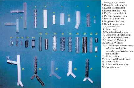
Figure 1.1. Overview of currently available stents (Freitag 2000). The Dynamic stent is listed as piece 29, also, the Dumon (3-4, 28), Polyflex (5-7), Hood (9), Gianturco (10), and Palmaz (11) which were some of those previously mentioned.
The Freitag dynamic stent is the only current “D” shaped airway stent on the
market, which was developed through analysis of CT-scans of various patients. This stent
consists of steel horseshoe shaped struts enveloped in silicone, with a silicone face without
struts that makes up the flat side that lies against the esophagus. These steel struts are useful
in maintaining the lumen against external compression, whereas the silicone face without
struts allows for compression during cough(Freitag et al. 1994). The struts are also spaced
at intervals similar to those of the cartilaginous rings surrounding the trachea, which helps
to prevent migration, as the struts should fit snugly between the rings. In addition, the
length can also be cut to fit more appropriately to each patient (Freitag et al. 1994). This
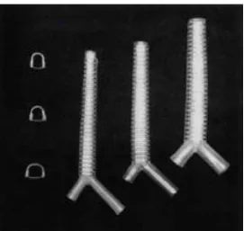
design can be observed more closely in Figure 1.2, which also shows the slight increase in
diameter towards the bifurcation point.
1. Montgomery T-tubes 2. Orlowski tracheal stent 3. Dumon tracheal stent 4. Dumon bronchial stent 5. Polyflex tracheal stent 6. Polyflex bronchial stent 7. Polyflex stump stent 8. Noppen tracheal stent 9. Hood bronchial stent 10. Gianturco stent 11. Palmaz stent
12. Tantalum Strecker stent 13. Uncovered Ultraflex stent 14. Covered Ultraflex stent 15. Uncovered Wallstent 16. Covered Wallstent 17-24. Prototypes of metal stents
and compound stents currently tested preclinically and clinically
25. Westaby stent
26. Bifurcated Orlowski stent 27. Hood Y-stent
Figure 1.2. Examples of Freitag stent, in three different sizes (Freitag et al. 1994). To the left is a representation of the increase in size towards the bifurcation point. The steel struts can be seen, which are horseshoe shaped, and do not interfere with the solid silicone back wall.
Freitag et al., described the importance of a dynamic stent after analyzing CT-scans
of tracheas, and finding that they are not uniformly structured throughout(Freitag et al.
1994). As such, they were also able to model the effects of normal airway breathing and
coughing when stents of different types were in place. Unlike the Freitag stent, most stents
do not allow for a cross-sectional change in lumen diameter during coughing and forced
exhalation, the critical velocity of airflow to move mucus is not reached; this can cause
mucus buildup and blockage, which can be just as problematic as a weak walled trachea.
Freitag et al. approximates that fifteen percent of patients with airway stents develop
clinically significant obstruction due to inspissated secretions, since the cilia, which would
Unfortunately, this stent is often skipped by medical professionals at times as it is difficult
to deploy and remove, even though it is most similar to natural trachea shape.
Preliminary data produced by Freitag et al. describes the changes in diameter that
the trachea undergoes when rigid and dynamic stents are present, and their ability to respond to coughing, to show that a “D” shaped stent would be most effective. The results
of coughing can be seen in Figure 1.3, which illustrates the velocity of air through the
lumen, which is lowest in the rigid stent model. In addition, these tests showed that an ideal
stent should be able to change in regard to cough pressures; this is accomplished by the
flexible membrane on the posterior side of the stent, which allows for reversible reduction
of cross-sectional area. The use of a silicone flexible membrane also counteracts the
tendency of metal stents to induce disproportionate granulation formation when exerting
high localized pressures (Freitag et al. 1994).
In the design of the Freitag stent, one hundred and fifty patients’ airways were
modeled using computed tomography (CT) to determine shape profiles which include the
average and standard deviation for the regions one centimeter below the vocal cords, the
middle of the trachea, and one centimeter above the carina, and is presented in Figure 1.3
as well(Freitag et al. 1994). This image also shows how the models depict the flattening
of the trachea as one progresses up cephalically from the carina towards the cricoid. By
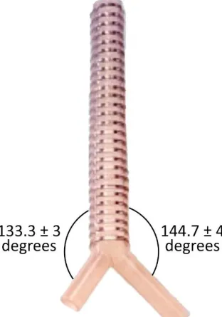
reproducing this information through computer-aided design (CAD) software, models were
made that determined the average branching angles at the carina from the main bronchus
to be 144.7±4° to the right and 133.3±3° to the left, depicted in Figure 1.4 (Freitag et al.
(a) (b)
Figure 1.3. Shape profile of trachea. (a) Depiction of tracheal diameter change subjected to rigid and dynamic stents. When flow is equal through the lumen, the velocity in the rigid stent is the lowest(Freitag et al. 1994). (b) Average shape of trachea determined through CT-scans of 150 patients (Freitag et al. 1994). Bars indicate variance of the standard deviation at each point.
Figure 1.4. Branching angles at the carina from the main bronchus.
1.2 Animal Testing
Piglets and adult mini-pigs that weigh 23 ± 6 kilograms on average, have been
instruments can be used for both species (Marquette et al. 1995). As such, Marquette et al.
describe in detail methods for inducing malacia in pigs, which is improved upon by
Saueressig et al. After induction of malacia and stent deployment, inflammatory response
can be analyzed through tests such as reverse-transcriptase polymerase chain reaction
(RT-PCR) and enzyme linked immunosorbent assays (ELISA).
Before inducing malacia, the animals must be placed under general anesthesia, after
8 hours of fasting from food and water (Saueressig et al. 2011), and in the case of Marquette
et al., intravenous propofol was used at 2 to 3 mg/kg to begin, with a continuous infusion
at 10 mg/kg·hr (Marquette et al. 1995). Ventilation was also provided during surgery either
by a cannula at the proximal port of endotracheal tube, or to the rigid bronchoscope. To
create the malacia, extramucosal resection of approximately 50% of the circumference of
three consecutive cartilaginous arches is performed, then, beginning two weeks later, a
23% solution of NaOH at pH 14 was applied to the mucosal area (inside the trachea) at the
level of the resected cartilaginous arches via cotton swab (Marquette et al. 1995). As
determined by Marquette et al., and confirmed by Saueressig et al., the best technique for
NaOH application is to restrict the application to two thirds of the bronchial circumference,
or avoid the posterior wall, because the caustic properties of the solution will become too
severe if the entire circumference is treated (Marquette et al. 1995; Saueressig et al. 2011).
Subsequent application of the solution was carried out during weekly bronchoscopies, as
needed, to remove necrotic tissue after stenosis of greater than 50% was found, although
three applications was typical (Marquette et al. 1995; Saueressig et al. 2011).
Stent deployment of an uncovered Palmaz stent into these porcine tracheas induced
21; however, after day 21, the stent was no longer molded to the bronchial wall due to
moderate to severe crushing of greater than 50% (Marquette et al. 1995). Dacron covered
Palmaz stents migrated distally, and thus blocked the left upper lobe bronchus, resulting in
pneumonia; and two tests with covered self-expanding stents were deemed inconclusive
overall as one stent was expectorated, and in the other case, the pig died due to respiratory
obstruction 4 days after the operation, though it was determined the stent did migrate
proximally during that short amount of time (Marquette et al. 1995).
Fibrosis and necrosis were found to occur in the region of the excised cartilaginous
arches, mainly in the submucosal and adventitious layers (Saueressig et al. 2011). In order
to determine the latero-lateral and anteroposterior diameters of the tracheal lumen, the
program Sigmascan Demo-Image Analyser by Sigma, was utilized, which uses the
equation:
𝐴𝑟𝑒𝑎 (𝑚𝑚2) = 𝜋 ∙ 𝑠𝑎𝑔𝑖𝑡𝑡𝑎𝑙 𝑑𝑖𝑎𝑚𝑒𝑡𝑒𝑟 (𝑚𝑚)
2 ∙
𝑐𝑜𝑟𝑜𝑛𝑎𝑙 𝑑𝑖𝑎𝑚𝑒𝑡𝑒𝑟 (𝑚𝑚)
2 eq.1
to calculate the area of the tracheal lumen (Saueressig et al. 2011). Tracheal inflammatory
stenosis (narrowing) and malacia are caused by trauma and ischemia, a restriction of blood
supply, to the mucosa, therefore calculating the area proves valuable to quantify the
presence of inflammation and fibrosis (Saueressig et al. 2011).
It is most typical for granulation tissue to form as a result of impaired mucosal
blood supply (Freitag et al. 1994); therefore, with regard to inflammatory response in live
models, testing of an array of cytokines can be performed to quantify immune response.
The body houses a multitude of cytokines, which is a broad term that describes factors that
or transforming growth factors (TGF), and interferons (IFN), etc. As each regulating factor
has different activity and targets, these can be used to develop an overall understanding of the immune response to a particular “intruder” through assays such as the previously
mentioned RT-PCR and ELISA.
These processes are different in that ELISA utilizes antibody specificity to test for
the presence of an antigen in the sample, which is generally displayed through a color
change, whereas RT-PCR is a process that allows for the formation and amplification of
complementary DNA strands, which are analyzed for gene expression through the
quantification of fluorescent probes linked to the cDNA (Thanawongnuwech et al. 2004).
This quantification has taken the place of northern blotting, which was previously the
standard used to separate RNA based on applying a charge to an agarose gel stained with
an UV fluorescent material such as ethidium bromide, the gel acts to trap the molecules
based on their size and structure (Thanawongnuwech et al. 2004).
Previously, Dozois et al., provided the basis for targeting and evaluating porcine
cytokine expression through the determination of the oligonucleotide sequences necessary
for gene specificity through RT-PCR. In addition, Dozois et al. was able to determine the
optimal range of PCR amplification cycles to be between 27 and 38, as well as detect the
presence of two housekeeping genes that are useful during RT-PCR, β-actin and
cyclophilin (Dozois et al. 1997). However, one of the most important things to remember
about RT-PCR is that it does not allow for comparison of the amount of mRNA between
cytokines, as the quantitative amounts are in relation to the whole (Dozois et al. 1997).
of the amount of protein being produced (Dozois et al. 1997). Both tests are useful as they
can be completed fairly quickly, and only small amounts of starting material is needed.
During testing of the live animal models, bronchoalveolar lavage (BAL) can be
used to collect epithelial lining fluid and bronchoalveolar cells, after flushing the cells with
phosphate buffered saline (PBS) (Costa et al. 2013). This fluid may then be tested for
cytokines such as IL-1α, IL-1β, IL-2, IL-4 Il-6, IL-8, IL-10, IL-12, TNF-α, TGF-β1, and
IFN-γ which are all classified as proinflammatory cytokines, which essentially means an
increase in their production leads to an increase in inflammatory response
(Thanawongnuwech et al. 2004). TNF-α and TGF-β1 are considered integral in the
formation of granulation tissue and fibrosis accumulation as the former acts as a trigger for
fibrosis occurrence, and the latter is a direct growth factor for fibroblast proliferation and
extracellular matrix production (Xing et al. 1997). In pigs infected with Mycoplasma
hyopneumoniae, the levels of IL-1, Il-6, and TNF-α are seen to increase; however, in pigs
infected with swine influenza, IL-1 and TNF-α levels are decreased (Thanawongnuwech
et al. 2004). This shows the variability of response, which is why blanket testing of
numerous cytokines is important, as thus far, the cytokine responses in pigs is not as well
outlined as in humans.
In the experiments performed by Thanawongnuwech et al., levels of cytokine
response and the correlating protein production were evaluated at 10, 28, and 42 days after
initial infection with M. hyopneumoniae to determine if specific cytokines could be
associated with certain acts (Thanawongnuwech et al. 2004). It was determined that
function (Thanawongnuwech et al. 2004). As the concentration was dramatically
increased, it is thought that it was able to alter the targets of the host immune response
away from a Th1-type response, which should have cleared the infection
(Thanawongnuwech et al. 2004). In addition, IL-12 levels remained high over the course
of the 42 days, leading to increased production of interferon-γ, which when over-produced
may lead to autoimmune disorders. RT-PCR was used with all of the previously listed
cytokines to determine density, and ELISA assay was used to measure the levels of IL-1β,
IL-8, IL-10, and TNF-α at undiluted concentrations (Thanawongnuwech et al. 2004).
1.3 Existing Lung Chambers
Prior to animal testing, it is important to determine the viability of stent design
through the use of excised lungs in a chamber that replicates breathing, so as to reduce the
probability of injury to a live animal. As porcine lungs are relatively easy to acquire, one
does not need to be euthanized for the sole purpose of performing viability tests.
Freitag et al. placed excised tracheas in a Plexiglas chamber with the distal ends of
the trachea attached to a 10 L tank, which acted as a lung proxy, in order to study the
behavior of deployed stents during forced expiration, cough, and extrinsic compression.
Negative and positive pressures were applied to the chamber via a vacuum and pressure
source which alternated between +5 and -9 kPa (0.725 to -1.305 psi). In these experiments,
a cough was replicated through the attachment of a computer-controlled vibration device,
which produced quick pressure swings between +3 and -9 kPa (0.435 to -1.305 psi) (Freitag
et al. 1994). A comparison between the natural tracheal peak flow velocity to the peak flow
velocity with a rigid stent in place illustrates the importance of a dynamic stent design in
with values of 87 m/s and 50 m/s, respectively (Freitag et al. 1994). Testing of compliance
also demonstrated that even with large variations of natural tracheas (opposite effects of
patient with emphysema vs. patient with heart failure and no pulmonary disease),
deployment of a dynamic stent led to similar mechanical behavior between the cases when
comparing cross-sectional area to pleural pressure (Freitag et al. 1994).
Research conducted by Lilburn et al., used rodents to investigate airway responses
by performing ex vivo negative pressure lung ventilation, which included a right ventricle
catheter insertion to allow for flushing of the remaining pulmonary blood after excision
with heparin-saline solution and Dublecco’s PBS (Lilburn et al. 2013). The heart and lungs
were then moved together into an acrylic ventilation chamber with the trachea pointed
downwards and suspended in 5% w/v glucose solution, which helped to curtail dehydration
and edema of the tissues (Lilburn et al. 2013). The researchers used the suction properties
of negative pressure ventilation to fill the lungs with air, then released the pressure to allow
for exhalation. A water bell was used to determine the volume of exhaled air by measuring
the volume of displaced water (Lilburn et al. 2013).
Patents filed by Burt B Orden (US 4,167,070 A) and Robert H Estetter, et al. (US
6,874,501 B1) both describe techniques of chamber construction using rigid, translucent
materials, to create the overall housing, which describe chambers similar to the goal of the
present research (both depicted in Appendix A). The patent filed by Orden, was published
in 1979 and consisted of three air filled chambers, two of which housed single bladder
flexible membranes to represent lungs, which could be in communication with each other
present. One set is used to replicate the pressures caused by the muscles within the chest
when the arms are lifted and lowered; whereas the other represents the diaphragm. Both
sets of bellows work in similar manners, by increasing the pressure surrounding the lungs
when the corresponding bellows is collapsed, and decreasing the pressure when the bellows
are expanded, which provides the negative pressure needed for inspiration (Orden 1979).
For this schematic, the chambers are filled with air around the lungs, and each bellow works
independently of the others. To alter the pressure within the flexible simulated lung, a
pump, such as an alternating piston pump in this rendering, is used. Mass elements are
added to ensure that the position of the housing does not affect the simulated lung; these
work by applying pressure to the lung(s) to recreate various lung conditions for illustration
in erect, supine, and prone positions (Orden 1979).
US patent number 6,874,501 B1, filed by Robert H Estetter et al. in 2002, looked
to improve upon the existing design proposed by Orden by introducing liquid around the
lungs, as well as modifying the design to better represent lungs in the human body. As
liquid is known to normally surround the lungs, this change enables a more realistic simulation. In addition, Estetter et al., described that Orden’s mass elements were not
symmetrically placed, his simulated lungs only consisted of single bladders surrounded by
air, that his terminology was backwards to his depiction, and that these discrepancies would
lead to results that do not accurately replicate the activity of the lungs (Estetter et al. 2005).
In order to address these disparities, Estetter et al. first increased the amount of lung
bladders to match the amount of lobes a human has, of three on the right, and two
bladders/lobes on the left side. Each bladder is connected to a valve, which allows for not
mounted to be fluid tight between the left and right lungs, to represent the mediastinum,
which is described as the area between the lungs, normally filled by the heart, trachea,
bronchi, and esophagus. As the simulator houses materials meant to act as replicas of the
organs, to simulate their separation, this plate was added, to further the ability of each side
to act independently of the other. It is the opinion of Estetter et al. that the use of fluid
surrounding the lungs is a better method than rigid mass elements on the lung surface to
simulate gravitational effects of chamber rotation, so they chose to dismiss this aspect of design from Orden’s chamber (Estetter et al. 2005).
Both designs choose to include a bladder in representation of the heart as well;
however, both place the heart at opposite ends of their design from the trachea, which does
not correlate with anatomical correctness. Orden and Estetter et al. both describe the
inclusion of the heart bladder as a way to show how hyperinflation, as a representation of
an enlarged heart, will affect lung compliance. Orden accomplishes this by having the
flexible bladder representing the heart adjacent to a flexible portion of the otherwise rigid
wall separating the heart and lung cavities (Orden 1979). The heart and flexible portion of
wall are on the opposite end of the chamber from the simulated trachea, and therefore not
nestled in the lung, as in an actual person, it is unclear if this affects the outcome of
simulations to a high enough degree to be problematic. Estetter et al. also use a flexible
bladder to show how an enlarged heart can affect the lungs, but surprisingly do not place
theirs next to the left lobes of the lungs either, although it is again unclear if this is an issue.
Estetter et al. attach their heart bladder to the opposite end of the mediastinum, away from
inflation, thereby affecting the effect of the diaphragm on the cavity and lung (Estetter et
al. 2005).
1.4 Stent Customization
Ongoing research in the development of new stents mainly includes the availability
of customization, but there are also prototypes of nitinol stents that are temperature
dependent with the ability to be adjusted in vivo, as well as the possibility of inclusion of
phosphorus-32 , which would prevent the development of granulation tissue (Freitag et al.
1994; Tripuraneni et al. 2012). One case of customization came out of desperation for a
patient of low socioeconomic standing, who could not afford a prefabricated device.
Therefore, it was determined cost-effective to develop a heat polymerized acrylic stent, as
biocompatibility was already proven (Tripuraneni et al. 2012). Polyether was used as an
impression material, with an incorporated stainless steel wire to stabilize the mold
(Tripuraneni et al. 2012). Another approach to the custom route is being taken by Melgoza
et al., as they develop a program that integrates CAD to build custom stents.
The use of CAD allows the researchers to utilize the theory of inventive problem
solving with the process of quality function deployment which helps solve physical
contradictions related to geometry and material, to develop designs that will decrease the
product development cycle and costs, and increase the quality of individual designs
(Melgoza et al. 2012). The product design has the goals of “necessities” which include
biocompatibility, where no cytotoxicity is displayed by the prostheses; low migration rate,
with hopes of avoiding greater than 4 mm of vertical displacement; easy insertion and
removal, which is obtained by striving to match an elastic modulus between 1 and 15 MPa;
et al. 2012). CT-scans were used to configure stent design with the manufacturing device “Fab@Home” which can translate files of stereolithography format into three-dimensional
silicone product. The final design does contain a flat posterior portion, with a diameter of
1 mm, with a wavy vertical pattern (diameter = 2 mm) that is meant to fit between the
cartilaginous rings, spaced 10 mm apart (Melgoza et al. 2012). The future of this work
requires streamlining the printing process, as well as developing ways to ensure sterility
and most importantly, viability in the patient.
Through the stepwise process of developing a feasible design, which succeeds in
isolated tests through the pressure chamber, and then the live model, the desired result is a
biocompatible model that does not induce great inflammatory response. Due to the existing
knowledge of porcine cytokinetic responses, the applicable assays will help to validate
Chapter 2: Design Development
An appropriate ventilation chamber to house actual lungs is necessary for recreating
the conditions of the chest cavity, as a method to test novel stents, which have the goal of
being designed uniquely for individual malacias. To replicate conditions within the chest
cavity, an ideal chamber should be able to undergo negative pressure, as the lungs rely on
negative pressure ventilation for respiration.
Normal respiration occurs through the involuntary muscle control of the diaphragm
lifting and lowering at the bottom of the rib cage, as the rib cage expands and contracts.
The physiological action of inhalation is described by Grotberg (2009) as air being pulled
into the lungs through a vacuum created by the diaphragm contracting downward, also
pulling the lungs downward, in conjunction with the contraction of the external intercostal
muscles lifting the lower six ribs; this vacuum causes negative pressure in the lungs.
Exhalation acts in the reverse manner, reversing the vacuum as the diaphragm and external
intercostal muscles relax, allowing air to leave the lungs (Grotberg 2009).
Negative pressure ventilation also allows for regular hyperinflations to occur, to
overcome decreasing lung compliance due to decreasing surfactant levels during normal
respiration (Uhlig & Wollin 1994). During hyperinflation, which occurs in the body
approximately every five minutes as a deep breath, surfactant levels are regenerated, which
helps the alveoli remain open as they overcome a lower surface tension with the help of
surfactant, therefore avoiding atelectasis, a complete or partial collapse of the lung (Uhlig
Some testing methods, such as those stated by Freitag et al. (1994) do implement
the use of actual human tracheal tissue, although, only a section of a single trachea was
obtained from the donor to measure how well a variety of stents hold open the lumen, with
a tank attached at one end to act as a lung. In this case, stents are deployed and removed
from the same sample successively, which is not ideal for later deployments which are
subjected to progressively worsening conditions, as deterioration occurs inside the lumen.
Since Freitag et al. only used a section of trachea, this was not ideal for the purposes of the
Tracheobronchial Stent Design (TSD) team due to the desire to target the primary, and
potentially, secondary bronchial region of the lungs. In addition, this methodology was not
repeated here because of the use of positive pressure ventilation, which occurs when air is
forced into the lungs, and is not ideal for testing with lungs as this sort of ventilation can
lead to over-inflation and edema formation, causing damage to the lung (Uhlig & Wollin
1994). Most simulation devices on the market use plastic and silicone lungs or sacs, and
even more rely on positive pressure ventilation, therefore, a new chamber needed to be
designed.
Because negative pressure ventilation is preferred, it was the goal of this research
to design a chamber that would meet the aforementioned conditions of housing lungs and
performing ventilation by negative pressure. If successful, the chamber would provide a
method to test novel stents beyond the main tracheal region to the primary and secondary
bronchi of the respiratory tree. Therefore, there is a need for the use of actual lungs, and
porcine lungs were chosen due to their similarity in size and ease of access to obtain. By
system, which includes the chamber itself; a way to monitor pressure changes; a conduit to
attach the trachea to the chamber, allowing it to be open to atmosphere; lungs; diaphragm;
and control mechanism of diaphragm to adjust pressure similarly to the mechanism used
in the body.
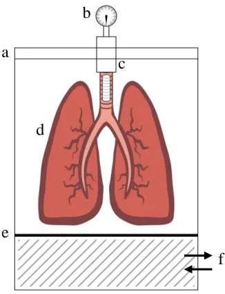
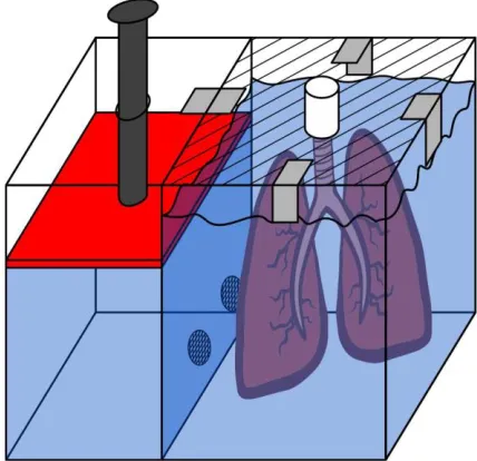
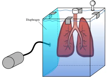
Figure 2.1. Schematic of design constraints. Proposed design needs to house lungs in rigid container, which has air tight seal (a), a pressure monitor (b), lung attachment (c), lungs (d), diaphragm (e), and contain a method for adjusting pressure in diaphragm (f).
2.1 Dismissal of Need for Tissue Fixation
Design of the needed ventilation chamber began by attempting to recreate the
conditions of the chest cavity. One of the first considerations included discussion of tissue
fixation, and whether or not it was necessary or optimal for testing. Fixation is used to
preserve tissues after removal, in a life-like state which stops decomposition so that cellular
processes that were underway just prior to removal can be viewed (Klatt 2014).
It was decided not to attempt fixation of the lungs for numerous reasons. First, the
amount of tissue present would require a fixation procedure that could last for weeks, and
as a ratio of 10:1 of fixative to tissue is recommended for ideal fixation, the amount of a
b
e
c
d
fixation would be no more than 5 mm thick, and no larger than a postage stamp
(approximately 2 cm). In addition, fixing at this size can still take three to seven days
(Randolph-Habecker 2012). Second, the process would undoubtedly end with uneven
fixation as the outermost tissue would become fixed early in the process, making it difficult
to judge progress of the interior tissue, and making it more difficult for the chemicals to
reach the innermost tissue (Trachsel et al. 2011). Third, fixation would decrease the
compliance of the tissue, therefore, the tracheal tissue would become stiffer than untreated
tissue, and would not retain the same characteristics of tissue that stents would be in contact
with after implantation.
There are protocols in “plastination” of tissue, but these would not be considered
for these purposes, as this process solidifies the tissue, replacing water and fat with
polymers such as silicone and epoxy, resulting in a solid piece that would not contract and
expand with ventilation (von Hagens et al. 1987). In addition, with plastination, the tissue
would become less likely to be damaged; whereas this is an important variable to consider
during stent deployment, as if tearing of the tissues occurs with an excised lung, damage
in live tissue would definitely be expected. Because this damage leads to granulation,
which can advance to the point of blocking air flow into the lungs, potential to damage
tissue would remain an important variable to consider. As porcine lungs can be obtained
fairly cheaply from a slaughterhouse, it was accepted that fresh lungs would be purchased
as needed for measurement and testing.
2.2 Proof of Concept and Material Selection
pressure could be obtained in a rigid chamber; a square box was obtained, not large enough
for testing with actual lungs, made of acrylic with 12.7 mm (0.5 in) diameter, and pressure
was applied to a rubber diaphragm sealed to the top of the chamber. Pressure was applied
via a compressor, which immediately indicated that a smoother, steady, and slower
application of pressure would be necessary to replicate breathing. At the time, a vacuum
was not available, although the sides of the chamber and lid noticeably bowed, indicating
the chamber was under pressure.
Research was conducted to find a suitable chamber already on the market, which
would be an appropriate size to fit snugly around porcine lungs and a diaphragm to provide
minimum volume around the lungs, rigid as a rib cage would be, would be cost effective,
and able to be sealed to prevent leakage of water or air when pressure was applied. A
suitable chamber already on the market was not found. Therefore, it was determined that Lexan™ (polycarbonate), a rigid material, would be preferable to Plexiglas® (acrylic) as
acrylic is more prone to shatter, although acrylic is less likely to scratch. In addition,
polycarbonate is able to undergo a higher number of cycles in an autoclave, and better
withstands the application of pressure, as it is virtually unbreakable. Both materials are
able to undergo a process similar to welding, where methylene chloride is used to fuse the
material together (Gore et al. 2014). Glass was also considered as a potential material,
however, it would be likely to shatter easily in comparison, as acrylic is four to eight times
stronger than glass, and polycarbonate is 200 times stronger. Additionally, glass would
2.3 Evaluation of Early Design Concepts
Initially, a cylinder was desired for the body of the chamber, but there was difficulty
finding a cylinder of ample size, to fit around the porcine lungs, which were found to have
average dimensions of 45.72 cm (18 in) from the superior end of the trachea to the inferior
portion of the lungs, 20.32 cm (8 in) of total lateral distance of both sets of left and right
lobes, with a depth of 7.62 cm (3 in) across the frontal plane from ventral to dorsal. These
averages were provided by the slaughterhouse, and verified once acquired. In addition to a
cylindrical body, a lid that screwed onto the chamber was desired, to further ensure air and
water leakage would be blocked. Many cylinders widely available were not large enough
to house porcine lungs, were significantly more expensive than their sheet-made
counterparts, or were made of flimsy materials, which did not follow the recommendations
given to the Tracheobronchial Stent Design (TSD) team.
One early design, devised by Dr. Kolok and depicted in Figure 2.2, consisted of the
use of a six and a half gallon glass carboy, with the bottom cut off, to allow for the
diaphragm to be adhered. This design was rejected due to the difficulty cutting the bottom
edge away, worry of sharp edges tearing the diaphragm and being dangerous to the
operator, as well as difficulty adhering the diaphragm well enough to maintain a sufficient
seal. In addition, the size seven stopper that the carboy uses, would not provide a
sufficiently large surface for the addition of a barb to attach the lungs to. As the stopper
has a top diameter of 37 mm (1.46 in) and bottom diameter of 30 mm (1.18 in), attaching
a barb would have left little material in the stopper for support or other ports. The tracheal
as the base of the barb has a diameter of 27.15 mm (1.06 in). Also, adding ports to the
chamber could be dangerous and more difficult than desired.
Figure 2.2. Ventilation Chamber Concept 1. Representation of glass carboy, cut at flat end to allow for attachment of diaphragm. Trachea proposed to be attached to rubber stopper, size 7.
The second concept design, depicted in Figure 2.3, had a large body for the lungs,
with an angled side that narrowed to follow the form of the trachea. A plate surrounded by
a gasket, with a cutout on the bottom that fit around the trachea, was proposed as a method
to prevent fluid from leaving the body of the chamber, so that the trachea would not become
filled with liquid. The advantages of this chamber included that it would be shaped to fit
around the lungs and trachea, providing a tighter fit, as experienced in the ventral cavity;
the chamber would be able to accommodate numerous ports, such as inlets and outlets for
air or fluid; the diaphragm could be attached below the lungs, as shown, or attached to the
lid, which could lift off for placement of the lungs in the chamber.
Additionally, the tracheal end of the chamber could be constructed at a downwards
angle, which would follow the suggestions of previous work performed on rodents by von
Bethmann et al. and Lilburn et al., which describe chamber placement on a 20° angle,
the plate cutout around the trachea would be hard to standardize, even with a strong yet
compliant gasket to accommodate varying trachea dimensions, leading to leakage; and if
the diaphragm was attached to the lid, in parallel with the lungs, this would interfere with
the inflation of both the diaphragm and the lungs, as not much space would remain,
although with diaphragm placement at the inferior end of the lungs, it would be more
difficult to seal the diaphragm sheeting to the wall. Due to the over-complexity of this
design, it was rejected with the goal of defining a simpler design.
Figure 2.3. Ventilation Chamber Concept 2. Chamber with many angled portions, and removable plate that fits around trachea to block fluid.
A third design was devised with the assistance of Dr. Kolok, to be a square chamber,
separated by a plate with holes at the bottom, with a plunger on one side, to act as a
diaphragm, which is used to move fluid through the holes, while the lung sits on the
opposite of the plate. An illustration of this design can be seen in Figure 2.4, below. This
design would require an adherence area for the lungs, such as a barb that is open to
atmosphere to be installed on the detachable lid, which would be simple to accomplish.
In the middle plate, holes would need to be drilled at the bottom to allow for fluid
to be pushed and pulled by suction into and out of the side with the lung, causing the
pressure difference. In favor of this design would be a simple to construct chamber, which
allows for attachment of the trachea in a manner to prevent fluid from entering the lungs,
and the use of a plunger which can be manually or mechanically controlled. The downsides
of this design include difficulty ensuring the plunger can easily move enough in both
directions to provide the needed pressure difference, as well as the difficulty continuing to
control the plunger if it was deemed necessary to invert the chamber, as suggested
previously. Additionally, the plunger would likely leak, as the corners would be difficult
to seal, causing them to be susceptible to leakage. A permanently attached diaphragm
would not be optimal, as this blocks the ability to clean the chamber. The idea was proposed
to place pressure marks on the side of the wall, so that the displacement of fluid could be
monitored, but it was decided that this would not provide an accurate gauge due to different
lung sizes. This design was also rejected.
In Ventilation Chamber Concept 4, the diaphragm is vertical, just as the lungs are,
which does not fully mimic the body, but the chamber could potentially be rotated to lay
with the trachea and lungs horizontal. With this particular design, the diaphragm would be
attached on one side near the opening and closing of the lid, and also would be expanding
beside the lungs, which both could potentially cause interference, as also discussed with
Concept 2. The top lid would require a gasket, and would need to be clamped. In addition,
without a release for fluid, the chamber could not be filled to capacity, although a port
could be added if necessary. Optimally, a pump would control the diaphragm, which could
be achieved by attaching a rod to the diaphragm, or by filling the diaphragm with fluid.
Attaching a rod to the diaphragm presents more problems, as the most secure fit would
likely result in having a hole in the diaphragm, which would lead to sealing issues.
Figure 2.5. Ventilation Chamber Concept 4. Diaphragm placed parallel beside lungs, which are attached to lid and open to atmosphere. Gasket and clamps required around lid.
2.4 Choosing a Diaphragm
As the body uses a diaphragm to control the movement of air, a method of adding
one to a ventilation chamber was needed. The diaphragm needs to meet the criteria of being
air tight, water tight, and have a high compliance and tensile strength. Numerous materials
were considered, before settling on a two tube latex bladder that is typically used in
sphygmomanometers, more commonly referred to as blood pressure cuffs. Two sizes were
obtained, with the specifications of: 20.32 cm by 6.35 cm (8.0 in by 2.5 in) for the smaller
bladder, and 38.1 cm by 11.43 cm (15 in by 4.5 in) for the larger bladder when fully
inflated. The bladders were estimated to be cylindrical when filled completely, and
therefore, volume was estimated as:
𝑉𝑐𝑦𝑙𝑖𝑛𝑑𝑒𝑟= 𝜋𝑟2ℎ eq. 2
Estimated volumes of 643.36 mL (39.26 in3) and 3,778.20 mL (230.56 in3) were calculated.
The thickness of material was measured to be 0.82 mm (0.03 in) of both bladders. Figure
2.6 represents the chosen bladder used as a diaphragm. The two tubes were attached to the
chamber via barb fittings, for inflation and deflation by pumps connected inline, on the
exterior of the chamber.
A sheet of 1.5875 mm (1/16 in) ultra-strength silicone rubber was obtained from
McMaster-Carr, and used in the initial testing. Although this material was compliant, for
simplicity, further iterations of the design required a diaphragm such as the bladder.
Problems sealing a rubber sheet to the chamber in a manner that would allow leak-proof,
controlled air flow, which was also easily adjustable, showed that a sac-like diaphragm
The smaller bladder was unable to provide pressure differences needed to replicate
breathing in the lung. The larger bladder fared better, as it did affect the pressure of the
chamber enough to allow the porcine lungs to inflate and deflate to accepted values similar
to those experienced in humans, these results are further discussed in Chapter 5.
Figure 2.6. Two Tube Bladder Used as Diaphragm Substitute. Attached to pumps through barb fittings in the lid for inflation and deflation.
Other diaphragm materials were considered, such as an inner tube from a tire, a balloon, and 1/16” ultra-strength silicone rubber sheeting. An inner tube was purchased,
but found to be much too rigid of a material, with very little flexibility. In addition, the
material would not be pliable enough to allow itself to be easily manipulated in the
chamber. A balloon was dismissed as a diaphragm due to doubts in the strength and
durability of the balloon, and the nature of having to overcome the tensile properties of the
balloon at rest before it expands; in addition to inconsistent elasticity over the course of
many trials. Also, the bladder obtained allowed the greatest amount of flexibility in
placement and adherence inside the chamber, which proved useful during testing of
chamber prototypes.
2.5 Pressure Monitoring
In order to monitor the flow of air into and out of the lung, a spirometer was attached
to the lid of the chamber, opposite the trachea. This setup allowed the trachea to remain
open to atmosphere, as the mouthpiece allows gas to pass through a filament between the
trachea and atmosphere. Spirometers calculate the volume of air inspired and expired by
the lungs, so this is a useful test to determine if enough negative pressure is being applied
by the diaphragm. A PASPORT Spirometer (PS-2152, Roseville, CA) by PASCO was
used, with disposable mouthpieces of the Lilly type.
Lilly spirometers, also known as pneumotachometers, measure the difference in
pressure before and after a membrane with known resistance. The Fleisch version is
generally accepted to be more reliable, as they measure the difference in pressure through
a series of parallel capillaries, though for the data required to monitor flow into and out of
the trachea and lungs to atmosphere, as desired by the project sponsor, the Lilly type is
acceptable. Both types rely on the Venturi principle that gas particles accelerate as their
flow zone is reduced (Brown et al. 1986; MacIntyre et al. 2005).
The preliminary designs contained methods to monitor the pressure inside the
chamber, which was not incorporated into the final design, as the spirometer was able to
distinguish flow into and out of the trachea, which is valuable. One such method was for a
water column, for example, by attaching stackable manometer tubes from a lumbar
puncture kit or a flexible tube, but as the size of the chamber grew, this method was
discarded, as the focus moved to measuring the volume of flow into and out of the lung.
Also, the original goal of the water column was to replicate the amount of pressure change
body (McGuire et al. 2014). However, as the ventilation chamber does not hold the lungs
as closely as the rib cage of the same body, the volume around the lungs would not be
comparable between the two systems.
In the body, the pleural space normally contains approximately 0.1 mL kg-1 of fluid, such that greater than 7 to 14 mL is considered abnormal in humans. Additionally, the
pleural sac is generally only 10 to 20 μm in width, which would not be achievable in the
Chapter 3: Design Prototypes
The first and second constructed prototypes were developed from 6.35 mm (0.25
in) Lexan™ polycarbonate as rectangular chambers with a removable lid, held in place by
two and four vertical hold-down toggle locking clamps (DE-STA-CO® 317-U),
respectively, with an added rubber gasket to help seal the chamber. The first edition of the
chamber, Prototype 1, pictured in Figure 3.1, proved to be oversized, with inner dimensions
of 59.69 cm x 36.83 cm x 19.05 cm (23.5 in x 14.5 in x 7.5 in). Prototype 1 also contained
a plate on the interior to adjust the usable space of the lung compartment. This design was
quickly deemed too large, as the lungs had no support, and the bladder was unable to
A smaller chamber was subsequently constructed, Prototype 2, with inner
dimensions of 36.83 cm x 25.40 cm x 8.89 cm (14.5 in x 10.0 in x 3.5 in), which fit much
more tightly around the lungs, particularly in the smallest dimension. The lid of both
Prototype 1 and Prototype 2 housed three ports: conduit for connection of trachea to
chamber, and two fittings to attach the two tubes of the diaphragm on the inside of the lid,
and for connection to the pumps on the outside of the chamber. The ports utilized plumber’s
tape and aquarium grade silicone to deter leakage.
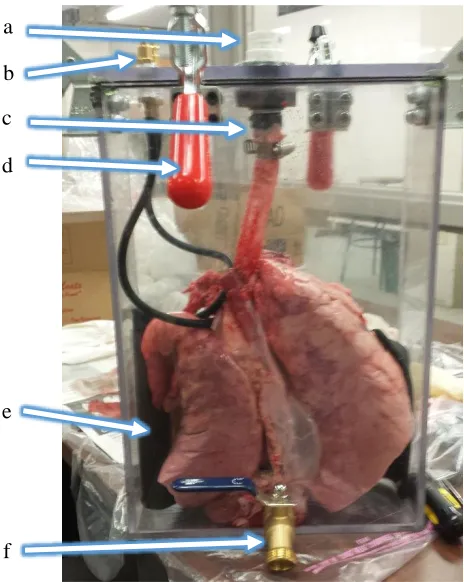
Figure 3.2 is an image of Prototype 2 with the proposed plate, clamps, bladder, and
tracheal barb visible. A valve was also added to allow for addition of fluid when lid is
already in place. This is particularly useful when the chamber is tilted horizontally. These
features are discussed in more detail following the image.
Figure 3.2. Image of Prototype 2. (a) Spirometer attachment piece, (b) fittings for pump a
d c b
e
The barb fitting for the trachea had dimensions of 3.37 cm (1.32 in) in length, and
14.28 mm (0.56 in) in width, which allowed for attachment with minimal restriction to the
potential for air flow into and out of the trachea to atmosphere, as the larynx was removed
from the lung sets. Opposite the tracheal barb, the spirometer was attached, with the
outflow side of the mouthpiece attached to the lid, and the side normally reserved to be
sealed by the lips, which is slightly smaller, left open to atmosphere. This direction was
important and kept consistent so the sensor would not report values opposite to the actual
flow, and would replicate normal use of the sensor.
Additionally, the rubber diaphragm was positioned and adhered to the chamber in
a few different ways, for optimization of the design. For one iteration, the bladder was
adhered to one of the large sides of the chamber, at the bottom. In another iteration, the
bladder was adhered only to the short edges of the chamber, in an effort to allow one lobe
of the lung on either side of the bladder, as the lobes appeared to be weighing down the
bladder in the previous arrangement. As the bladder would occasionally not return to its
natural shape, a horizontal plate was proposed to separate the bladder from the lungs.
Prototype 2 was not large enough to allow for this configuration with a lung in place, so
the design was tested with a balloon, and showed great promise. The next prototype was
developed with the addition of the plate as a consideration.
For Prototype 2, the DE-STA-CO clamps were added to the middle of the two short
edges, as well as on the long edges, offset, with one on either side of the centered trachea
attachment piece. The clamps on the long edge could not be centered due to interference
with the spirometer and the horizontal arms of the clamps. These clamps were unable to
this design. In addition, the clamps would cause the walls of the chamber to bow outwards
when pressure was applied, further disrupting the seal. As the goal of this design was to
have the ability to invert the chamber when desired, similarly to the previous work by von
Bethmann et al. and Lilburn et al., any leakage was not an acceptable solution. A second
gasket was added around the edge in an effort to reduce leakage, which did help to reduce
leakage, however, fluid from the lungs began escaping through the spirometer, which
negates the potential to retrieve results, as the spirometer filament would become
contaminated.
3.1 Final Prototype Design
Prototype 3 was developed based on the shortcomings of the prior two prototypes.
First, the dimensions in the x and y planes became 54.61 cm x 34.29 cm (21.5 in x 13.5
in), which were more similar to Prototype 1; however, the depth was more similar to
Prototype 2, at 10.16 cm (4.0 in), a half inch increase over its predecessor. Table 3.1
displays the progression of sizing for the three chambers.
Table 3.1 Inner Dimensions of Prototypes in Relation to Average Lung Size
Height (X) Width (Y) Depth (Z)
Average Size of Lungs 45.72 cm (18.0 in) 20.32 cm (8.0 in) 7.62 cm (3.0 in)
Prototype 1 59.69 cm (23.5 in) 36.83 cm (14.5 in) 19.05 cm (7.5 in)
Prototype 2 36.83 cm (14.5 in) 25.40 cm (10.0 in) 8.89 cm (3.5 in)
Prototype 3 54.61 cm (21.5 in) 34.29 cm (13.5 in) 10.16 cm (4.0 in)
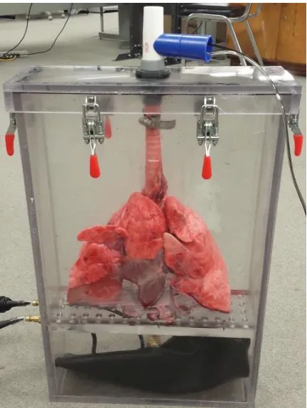
Prototype 3, depicted in Figure 3.2, was developed to include a lid with an O-ring,
323) were utilized, and placed evenly around the chamber, which held the lid in place
securely. A plate was added 15.87 cm (6.25 in) from the bottom of the chamber, to separate
the diaphragm from the lungs, and the diaphragm tubes were attached to the wall below
the plate. The plate is screwed in place to maintain each compartment, and prevent it from
moving should the chamber be tilted or inverted. Attaching the tubes and pump hoses at
the level of the diaphragm, below the plate, allows for increased maneuverability of the
chamber, as the pump hoses do not become detached accidentally between trials as the lid
is removed and replaced; also, they do not cause any interference if the chamber is inverted,
which was observed in testing of Prototype 2. Additionally, the spirometer was attached
by a 3D printed connector, attached to the exterior of the lid, opposite the tracheal barb.
Prototype 3 was constructed of thicker material than the previous two prototypes,
to reduce flexing and bowing of the sides, as it is inherently more rigid. The polycarbonate
chosen for this prototype is 9.52 mm (0.375 in) thick, whereas the previous chambers were