CSEIT1835229 | Received : 07 June 2018 | Accepted : 20 June 2018 | May-June-2018 [ (3)5 : 900-907]
© 2018 IJSRCSEIT | Volume 3 | Issue 5 | ISSN : 2456-3307
Low Power BLE Module for Wireless Communication among
Speech Processor and Headpiece (Transmitter) of Cochlear
Implants
Prof. Ramesh K
Department of PG studies in Computer Science, Women‟s University, Vijayapur, Karnataka, India
ABSTRACT
The most recent cochlear Implants Naida CI Q70 and Q90 from Advanced Bionics have their external devices such as speech processor and head piece (transmitter) ,Communicate with the reliable connection oriented network architecture. This architecture is complex with a long cable connected between speech processor and head piece (transmitter).This structure encounter drawbacks, like maintenance of cable, much cost on its small damage. Furthermore its rare and unique structure attracts the multiple queries from the people. Hence the idea is to Design Wireless Communication system for a CI device is the thought process. The proposed Architecture uses the „UART to BLE 4.0 Wi-Fi module to configure Speech Processor and Head Piece (Transmitter) of CI as BLE 4.0 module that has hotspot for communication. In this paper we have provided sufficient results through simulation.
Keywords : Cochlear Implant, IC, Sound Processor, Transmitter, head piece, Electrode, Sound wave, Wi-Fi.
I.
INTRODUCTION1.1 Cochlear Implants
Cochlear Implant [8] are implantable devices designed with the goal of providing sound detection and speech recognition for the people who receive little or no benefit from the hearing aids. There are several manufacturers of cochlear implants such as Advanced Bionics [8] Corporation. The cochlear Implant regardless of the manufacturer is comprised of both internal and external components. The internal portion, which is implanted surgically, has a receiver and tiny electrodes. The receiver is imbedded under the skin behind the ear and the electrodes are surgically inserted into the cochlea.
Figure 1. Internal devices of CI
the signal from the speech processor to the internal part of the cochlea implant. It magnetically attaches to the surface of the head behind the ear at the spot where the internal portion of the implant is located [5].
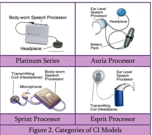
Platinum Series Auria Processor
Sprint Processor Esprit Processor Figure 2. Categories of CI Models
The internal and external portions work together to change sound into electrical signals that are sent to the hearing nerve. First, the microphone picks up the sound energy, and transmits the signal through the cord to the speech processor. The Speech processor filters [1],analyzes and converts the sound energy into a digital code that is then sent back through the cord to the headpiece where it is transmitted across the skin, via radio frequencies to the internal receiver. Then the internal receiver delivers the signal to the electrodes that have charge directly to the auditory nerve [10]. Finally the auditory nerve carries these electrical signals to the brain ,where they are interpreted as sound [2].This process occurs so rapidly that the listener will hear speech and other sounds without any noticeable delay.
1.2 A wireless communications system.
Communication is the transfer of information from the source to the destination [9]. In this process, resources are consumed: electrical power, RF
spectrum, computational resources or elapsed time. In this paper, we review how future trends will make it more challenging for wireless Cochlear devices to accomplish their communications objectives while efficiently using their limited resources. We begin with a review of some of the functions to be performed in the physical layer processing for a wireless communications system and some of the relevant characteristics of the RF wireless channel. We then describe how decisions about the allocation of system resources impact the ability of the system to be flexible and efficient. In particular, we will show that a static allocation of system resources to individual users and a static design of the individual wireless links will result in unacceptable levels of inefficiency. It is this need for an adaptive, flexible physical layer implementation that motivates the work in this paper.
II.
The problems in the present architectureThe major components of a CI include a microphone, Signal Processor, Implant Electrode and Batteries. The microphone is fitted in to or placed behind the patient‟s ear, and this captures the acoustic signals and converts it,to an Electrical signal. Using this information, the signal processor calculates the type and level of stimulation to deliver through the electrodes, which are surgically inserted into the cochlea. Large variations in signal processing algorithms exist due to diverse implementation methods and differing parameters among patients.
The Internal portion, which is Implanted surgically has a receiver and tiny electrodes. The receiver is embedded under the skin behind the ear and the electrodes are surgically inserted into the cochlea.
magnetically attaches to the surface of the head behind the ear at the spot where the internal portion of the implant is located [5].
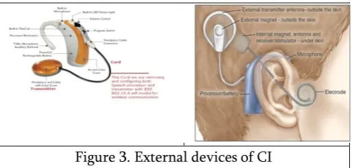
Figure 3. External devices of CI
We can see in fig (3) the cord that connects speech processor and the transmitter which are placed on the ear externally. The problem of this architecture [3, 6] is three fold
1. Need of good maintenance of cable and very expensive as any small damage requires huge money to be spent on cable.
2. Furthermore its rare and unique structure creates a lot of nuisance with multiple enquiries from the people leading to the frustration while answering them
3. Deaf population cannot keep the processor wherever they want ,but have to keep near the radius of the cord length.
Hence to overcome the above said drawbacks we are proposing the wireless architecture[14] based on BLE 4.0
III.
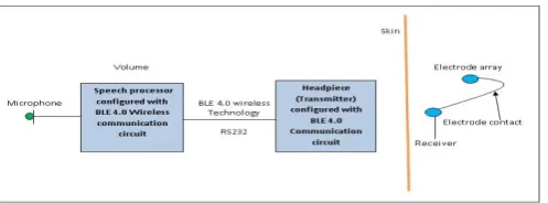
PROPOSED WORK3.1 The Idea: To overcome the problems we are proposing an Architecture[3,6] based on the Bluetooth Low Energy BLE 4.0 [4,11,12] as shown in the block diagram (fig 4) where Above Architecture uses the „UART to BLE 4.0 module‟ and it is available in local market.
Figure 4. Abstract diagram for proposed work
It provides Programme, tester and analyser to configure the BLE 4.0. The Idea is to configure the Voice processing system and the Head piece (Transmitter) as BLE 4.0 hot spot. BLE 4.0 module will connect Voice processing hotspot for communication with Head Piece (Transmitter). Maximum distance between two WIFI module as maximum as 100mts (practical around 30mts).
3.2 Thought Process
A system for managing wireless communication among external devices[14] Speech Processor and Head Piece (Transmitter) of CI , comprising :a first device including a Bluetooth Low Energy (BLE) wireless communication circuit configured to receive and transmit data using BLE wireless communication technology; and a second device including a BLE tester configured to wirelessly communicate with the first device and test the BLE wireless communication circuit according to a wireless test mode in response to a test command associated with the wireless test mode, the second device including an analysis initiator coupled to the BLE tester and configured to generate the test command in response to a signal requesting a diagnostic analysis of an environment of the wireless communication. according to a wireless test mode in response to a test command associated with the wireless test mode, the second device including an analysis initiator coupled to the Low
BLE 4.0 Wireless module Ear
Module
RS23
2
Voice Processing
System and Head
Piece (Transmitter)
power BLE tester and configured to generate the test command in response to a signal requesting a diagnostic analysis of an environment of the wireless communication, wherein at least one of the first device and the second device includes the Speech Processor and Head Piece (Transmitter) of CI as shown in fig(5).
Figure 5. Proposed Bluetooth Low Power BLE 4.0 wireless module configured for CIs External Devices.
3.3 Methodology
For wirelessly communication among External Devices Speech Processor and Head piece (Transmitter) of CI, comprises of wireless communication among the External Devices Speech Processor and Head Piece (Transmitter) of CI using Bluetooth Low Energy BLE wireless communication technology. Performing a diagnostic analysis of an environment of the wireless communication, including: establishing a wireless link between the Speech Processor and Head Piece (Transmitter) of CI and a BLE tester [11] for the diagnostic analysis. Testing the hearing quality of data transmission associated with the wireless link according to a specified wireless test mode; and producing information indicative of one or more characteristics of the environment of the wireless communication. The procedure goes as below
Performing wireless communication with the CI using Bluetooth Low Energy (BLE) wireless communication technology[11].
Performing a diagnostic analysis of an environment of the wireless communication, including:
o Establishing a wireless link between the Speech Processor and Head Piece(Transmitter) of CI and a BLE tester for the diagnostic analysis.
o Testing the CI for quality of data transmission associated with the wireless link according to a specified wireless test mode; and producing information indicative of one or more characteristics of the environment of the wireless communication.
Wherein testing the hearing in CI comprises producing at least one channel metric for each channel of a plurality of wireless communication channels, the channel metric indicative of quality of data transmission performed using the each channel.
Wherein producing the at least one channel metric comprises producing one or more of a packet error rate and a received signal strength indicator for each channel of the plurality of wireless communication channels.
Wherein testing the hearing aid comprises producing a channel map indicative of quality of data transmission using each channel of a plurality of wireless communication channels.
Further comprising enabling or disabling each channel of the plurality of wireless communication channels for performing the wireless communication using the channel map.
3.4 Technical Background
Radio waves are electromagnetic waves that can be used in wireless communication. The frequencies of these waves serve as physical communication channels. The radio frequency (RF) spectrum has a finite range of frequencies, and thus a limited number of channels. the spectrum is allocated based on what bands are used for what purpose.
Communication signals on the same channel interfere, assuming the strengths of the signals are non-negligible due to transmission power and distance. Also, communication signals on adjacent channels may interfere with communications on the desired channel because of inadequate filtering, tuning or frequency control. Adjacent channel interference can increase with an increase in signal power in adjacent channels.
Most countries of the world have allocated certain frequency spectrums for commercial use as “unlicensed” wireless bands. For example, the FCC has designated licence free bandwidth segments for industrial , scientific and medical (ISM} uses. Licence. Various commercial applications use this unlicensed bandwidth for short range wireless communication.
Channels are not allocated within the license-free band. Commercial devices designed to operate in the license-free band are constrained to transmit using a relatively low power, which allows more commercial devices to use the unlicensed frequency bands by increasing the reuse of a frequency. Spread spectrum systems mitigate interference by spreading their information over a much larger bandwidth than the information requires. This has the advantage of spreading any narrowband interference encountered within the channel over a large bandwidth which can then be integrated out by the receiver. The transmitter and receiver coordinate and manage the spreading sequences. This adds complexity and power to spread the signal using either fast frequency hopping or direct sequence phase manipulation. This added complexity and power may prevent these
schemes from being used in ultra-low power communications systems.
3.4.1 Bluetooth Low Energy Devices
Bluetooth low energy (BLE) is a distinguishing feature of Bluetooth version 4.0 wireless communication technology that provides low-power devices with short-range low-power wireless connectivity. Examples of such low-power devices include hearing assistance devices, such as CI devices and hearing aids. Each device having wireless connectivity, as discussed in this document, may be a device equipped with BLE-based communication capability (referred to as a "BLE device" herein). In other words, BLE technology may be implemented in each of the hearing assistance devices such as 101A-D and the communicator‟s 102A-101A-D. 1A-101A-D, the communicators 202 and 302, the programmer, the hearing assistance device, the assisted listening device, the streaming audio device, and the wireless audio controller (WAC). 2A-E and 3A-E, the WAC 405 and the hearing assistance devices. BLE communication may be performed between the BLE devices. Wireless test modes (also referred to as RF test modes) are generated for design verification and manufacturing test with such devices when implemented as BLE devices. Various embodiments use the same wireless test modes in the field to characterize an environment where problems occur with the BLE communication between such devices.
3.4.2 Test Modes
Processor of CI, and "the HP" refers to the “Head Piece of CI” under test. The Examples include:
1. Continuous packet transmit mode. The SP transmits packets with pseudo random data over the BLE channels, to be used by and HP (External Devices of CI) for RF characterization. 2. Downlink PER test mode. The SP transmits
bursts of data. The HP receives the bursts of data and calculates PER.
3. Uplink PER test mode. The HP transmits bursts of data to the electrode Inner device of CI. The Electrode receives the bursts of data and calculates PER.
4. Echo packet mode. The SP transmits a packet. The HP echoes the packet. The HP retransmits the packet. The SP receives the echoed packet and calculates PER.
5. Antenna test profile model. The HP transmits an unmodulated carrier signal. The SP detects the transmitted signal.
6. RSSI test mode. The HP has ability to report RSSI. The SP sets up connection with the HP and transmits "send RSSI packet". The HP receives "send RSSI packet" and calculates RSSI for received packet. The HP then sends packet with received RSSI value and channel number. The SP iterates on next channel in sequence. This process repeats for user a specified number of channels.
IV.
Results and DiscussionWe have processed input sound signal including the steps: a) performing a frequency analysis on the input sound signal to generate a plurality of analysis signals each corresponding to a channel within the input sound signal; b) applying a scaling function to each of the plurality of analysis signals in response to a control signal, such that for each channel, the minimum output level is modified in response to the control signal, while the maximum output level of the gain adjusted signal remains substantially
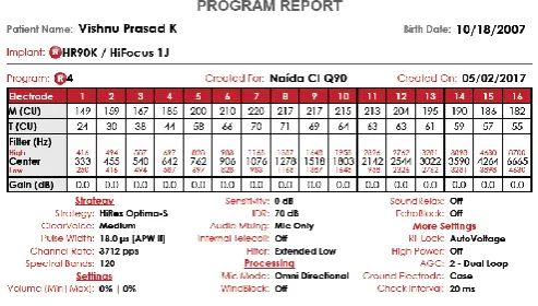
unchanged, we also expecting similar results for BLE 4.0 wireless environment when it is configured. We have used Clinical programming tool “Sound Wave”[8] from advanced Bionics for Q70 and Q90 recipient whose name is Vishnu Prasad K a profound deaf child. We have recorded NRI measurements on a subset of electrodes, distributed across the electrode array, such as 3, 7, 11, 15 and 16 as shown in figures 6, 7, 8, 9, 10.Our argument is to get the similar records when the complete hardware is developed for CI configured with BLE 4.0 wifi module.
4.1 NRI Recording Procedure
Set the electrode that, Sound Wave will use to measure the response during theNRI measurement.
The default setting is 2 apical unless the stimulating electrode is at the apical end of the array.
Set the starting and ending stimulation levels in Clinical Units (CU) as desired.
The default setting is from 100-200 CUs.
Stimulation Range may be set as ascending or Descending.
Data points are set to achieve an increment step size of 20-30 CU.
The default setting is 5 data points.
Stimulation sequence is set to achieve the polarity of the pulse used during NRI stimulation.
Average per data point set the number of stimulus presentations that will be delivered and averaged at each stimulation level.
4.2 NRI Response
Advanced Bionics Naida Q70 and Q90 processor with BLE 4.0 wifi module and when is tested.
Electrode array no‟s
Stimulation range in Clinical Units CU
NRI response in micro volts Low to High
tNRI recording in CU
3 140 – 260 119 – 533 103 7 100 – 220 32 – 315 148 11 180 – 300 74 – 440 159 15 180 – 300 85 – 366 162 16 100 – 220 27 – 135 150
Table 1. NRI response from electrode array
Similarly we expect the similar results when Advanced Bionics Naida Q70 and Q90 processor configured with BLE 4.0 wifi module and is tested for various environments responses which are recorded as shown in the table 2.
Sl No
Environments Response in percentage 1 Speech in Quiet 46% 2 Music 21% 3 Speech in Noise 28% 4 Noise 5%
Table 2 Environment response by Naida Q70 and Q90 processor
4.3 Simulation Results
In the simulation, we use complementary receiver operating characteristics (ROC) curves
Pmd versusmicrophonesignals
to show theperformance in 4 environments mentioned in table 2. From the figure (6), we notice that there is a great improvement in the performance with increase in signal reception. We find good performance even at noisy environment. Simulation results closely match with theoretical results.
Figure 6. Pd versus Microphone Signals curve
4.4 Test Details
The testing for the proposed architecture is done in Sound Wave simulation environment which is developed for CI Q90 processor of Advanced Bionics. The tests are done in real environment for a child suffering from profound deafness. The report is as below.
V.
Conclusion and Future workThe data collected in this study indicated that first Neural Response Imaging (NRI) thresholds had a better correlation with the most comfortable loudness (M) levels than tNRI thresholds. Electrically evoked auditory reflex thresholds (EARTs) had a higher correlation with High Resolution M levels than tNRI thresholds and a lower correlation than first NRI thresholds. NRI is a very useful method for programming the cochlear implants of young children who cannot demonstrate a reliable judgment of loudness.
VI.
REFERENCES
1. Chatterjee M: Modulation masking in cochlear implant listeners: envelope vs. tonotopic components. J Acoust Soc Am 2003, 113:2042-2053.
2. Loizou, P. (2006). "Speech processing in vocoder-centric cochlear implants," Cochlearand Brainstem Implants (ed. Moller, A.), Adv. Otorhinolaryngol. Basel, Karger, 64,109-143.
3. Loizou, P., Lobo, A., Kehtarnavaz, N., Peddigari, V. and Lee, H. (2006). Open architecture research interface for cochlear implants," Second Quarterly Progress Report,NIH-NOI-DC-6-0002.
4. SimpleLink Bluetooth low energy CC2640 wireless MCU Software Developer‟s Guide (SWRU393) 2
5. Peddigari, V., Kehtarnavaz, N. and Loizou, P. (2007). Real-time LabVIEW implementation of cochlear implant signal processing on PDA platforms," Proc. IEEE Intern. Conf. Signal, Acoust. Speech Proc, Honolulu, Hawaii (accepted).
6. Ramesh K .(2017) Wireless Transmission of Sound between Speech Processor and Transmitter for CochlearDevices" Journal of Advances in Information Technology Vol.8,No.1.feb 2017,ISSN 1798-2340
7. Ramesh K and Deepa Patil ( 2016) Embedding of Internal and External Components of Cochlear Implant on to a single IntegratedCircuit" IOSR Journal of Computer Engineering (IOSR-JCE) e-ISSN: 2278-0661,p-ISSN: 2278-8727, Volume 18, Issue 4, Ver. III
(Jul.-Aug. 2016), PP 14-19 www.iosrjournals.org
8. www.advancedbionics.com 9. www.nxp.com
10. An Introduction to IEEE STD 802.15.4 Jon T. Adams Freescale Semiconductor, Inc. 2100 E. Elliot Road, MD EL536 Tempe, Arizona 85284 USA +1 480-413-3439 [email protected]. 11. TI BLE Stack V2.1 www.ti.com/ble-stack 3. 12. CC2540 and CC2541 Mini Development Kit
User's Guide (SWRU270)
13. Ramesh k,Sumaya Sanober,Shivanand Lamani,S B Kulkarni EEE 802.15.4 Wi-Fi Module for Wireless Communication among Speech Processor and Headpiece (Transmitter) of Cochlear Implants." 978-1-5386-1887- 5/17/$31.00 2017 EEE.