Rules Decomposition for
Distributed Context Processing
Martijn Plass
title: Rules Decomposition for Distributed Context Processing name: Martijn J.A. Plass
student number: 9901523
chair: Architecture and Services of Networked Applications, University of Twente
location: Twente Institute for Wireless and Mobile Communication, Enschede graduation committee:
Abstract
The modification of context information or distillation of other information from context information is called context processing. In existing context processing solutions, this is often performed by the application of rules in a rule engine, running on a centralized server. When working in a distributed environment, this approach is often inefficient, or even unfeasible. Performing rules written for a system as a whole in a distributed
environment is often a complex task for the programmers of a system implementation. This project proposes a method to transform a set of rules written for a system as a whole into a set of rules that distribute functionality in a networked environment. Using the network topology, the capabilities of all system parts in the network and a set of translation rules, it is possible to divide a rule into components distributed over the network.
Table of Contents
1 Introduction...5
1.1 Motivation...5
1.2 State-of-the-Art...6
1.3 Objectives...7
1.4 Approach...7
1.5 Structure of the Report...7
2 Scenarios...8
2.1 Scenario Elderly Home...8
2.2 Scenario Task Outsourcing...9
2.3 Scenario Emergency Situation...11
3 Rule Distribution...13
3.1 Rules...13
3.2 Approach to Rule Distribution...13
3.3 Rule Decomposition...14
3.4 Use of Rule Decomposition...16
4 Formal Definitions...18
4.1 Rule Language...18
4.2 System Definition...18
4.3 Decomposition Process...19
4.4 Examples...24
5 Applying Rules to the Scenarios...29
5.1 Requirements...29
5.2 User Interactions...30
5.3 Rules...32
5.4 Architecture...33
5.5 Capabilities...33
5.6 Network Communication...34
5.7 Rules in the Task Outsourcing Scenario and Emergency scenario... 35
5.8 Middleware Architecture...35
6 Implementation...36
6.1 First Prototype...36
6.2 Second Prototype...38
7 Final Remarks...45
7.1 Research Results and Conclusions...45
7.2 Discussion...46
7.3 Future Work...47
Appendix A: Elderly Home Technology...50
Appendix B: Decomposition Compiler Input...51
Glossary...55
Preface
This is the report of the project “Rules Decomposition for Distributed Context
Processing” performed for the Twente Institute of Wireless and Mobile Communications. The project has been performed in the context of a masters graduation assignment for the University of Twente, Faculty of Electrical Engineering, Mathematics and Computer Science.
The work reported in this thesis is related to the Freeband AWARENESS project (http://awareness.freeband.nl) in which the University of Twente and TI-WMC participate. Freeband is sponsored by the Dutch government under contract BSIK 03025.
Acknowledgements
I would like to use this space to thank some people who have helped me during this project. First of all I would like to thank the graduation committee, Luís Ferreira Pires, Hartmut Benz and Patricia Dockhorn Costa, for their infinite patience in reviewing version after version of the report, and their continuing support during the slower parts of the project. I would also like to thank my girlfriend Danny Oude Bos for her moral support and tireless reviewing. And lastly I would like to thank my parents and all the other people who have pushed me on to finish this report and the other people that have spent their valuable time reviewing it.
Enschede, July 29th, 2007
1 Introduction
This chapter describes the motivation for the project, the objectives, the project approach and the structure of the report.
1.1 Motivation
In Information Technology, one branch of development is that of context-aware computing. Context-aware applications change the way they work depending on their users' context. Context-aware computing allows the application to react to the
environment so that what it does is more suited to the user. For instance, context-aware computing allows a cell phone to decide not to sound its ring tone in a cinema while the movie is being shown. Context is gathered from different sources like sensors, personal databases and other devices, and subsequently processed and used by an application. Context processing is the act of manipulating context information before delivering it to the application. This processing can take several different forms. For instance, each type of context source tends to have its own data format, which usually differs from the application's format. This means that if an application wants to use data from a context source that uses a different format, the data must be translated to the appropriate format. An example of this could be the translation of a GPS location to a street address, or the downscaling of the resolution of a video feed. Another form of processing is the distillation of higher order context information by combining lower order context information from multiple sources. For example, by combining a work schedule and the known location of a user, we might be able to conclude whether or not the user is in a meeting.
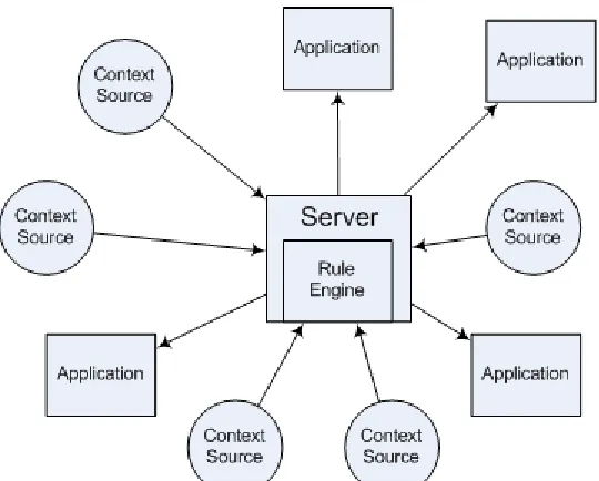
A common approach to designing and building context-aware applications is to apply rule-based systems [13,1,14,5,10,15]. Rules are designed to describe the behaviour that the system should have, by describing actions and under what conditions those actions should be performed. The rules are then executed by a rule engine in the application. The advantage of this approach is that the rules can be designed without in-depth knowledge of the system and they can be changed after implementation without having to make changes to the application. There are commercially available rule engine solutions that can handle very complex rules. Some examples are mentioned in section 1.2.
Systems that are developed using the rule-driven approach usually take a centralized form: Because everything revolves around the rule engine, the rules run on a centralized device (Figure 1). Such systems are fairly straightforward to implement and therefore often used. However, systems are frequently not a single device, but consist of lots of different devices connected by a network.
Development becomes more complex when the system is a distributed network instead of a single server. The functionality has to be divided among the devices in the network, which is usually a task for the programmers. If the network is large and a lot of devices have to co-operate, this task can become very complicated. That is why large distributed systems are sometimes handled as a centralized server architecture, where all the distributed capabilities of the devices in the network are ignored and a single device does all the processing, even though that may be far from ideal.
If rules that are written for an abstract system can be automatically translated into rules for a concrete, distributed system, this could potentially allow distributed systems to be designed without a large increase in complexity. This project looks at a way to define a method of breaking up a rule into individual components that can be assigned to devices in a distributed system. If this process can be formally defined, it can then be
Systems that could benefit from this approach include:
● Sensor networks and systems that incorporate sensor networks.
● Single purpose Ad Hoc networks such as emergency services, military applications, single-type device networks such as printers or alarm systems. ● Distributed computing applications.
In general, any distributed application that runs on a large distributed network could benefit from our approach.
1.2 State-of-the-Art
The practice of describing what systems should do in the form of rules has been around for a long time. Companies designed business rules that describe their policies and employee tasks. When those businesses became automated, the business rules were used to design the system. One of the problems was that policies change very often, which in the case of automation requires reprogramming computers and applications. To avoid this, the first rule engines were developed. They allowed computers to adhere to the business rules and could be easily changed to suit a new situation.
Currently, business rules are still used by companies to define policies and it is a
common approach to use a rule engine in a business application or framework [1, 14, 5, 10, 15]. There are not many general purpose rule engines, mostly because they are so complex. A lot of projects use their own, proprietary rule engine that has functionality tailored to the needs of the project.
The commercial general purpose rule engines that are in use today, such as Jess [9], Mandarax [11], Jena [8], Arete [3] and others, all work according to the centralized server approach. They all allow very complicated and expressive rules, but cannot handle a distributed environment. Integrating them into a distributed network would be the job of the programmers implementing the system.
There is a distributed version of Jess, called Djess [7], which allows rule engines running on different devices to share rules and facts in working memory. There is a central manager that keeps track of who is in the group of sharing rule engines. In this approach, the rule engines are distributed, but the rule management and the rules themselves are still the same as in a monolithic approach. Practically speaking, this is another way of forcing a distributed system to work like a monolithic system, although it is a much more elegant way than used in other solutions.
Sørensen et al. describe a context-aware middleware for Ad Hoc Environments [14]. It allows rule engines running on autonomous devices to exchange context data using a publish-subscribe model. Potentially it can be a good basis on which to build a context-aware distributed application, but it requires the rules for the rule engines on the
devices to be written and entered manually. For this project, we are looking for a way to generate those rules automatically.
The project “Code Blue” handles a situation very similar to the third scenario that we define in our project, which is an emergency situation involving medical personnel. “Code Blue” is currently under development [6]. The main difference with our scenario is that we focus on the dynamic nature of the network, while in Code Blue the network is considered to be static; nodes may move around, but devices will not leave or join the network.
1.3 Objectives
The objectives pursued in this project have been:
● To formally define a method to translate a rule written for a high level abstract system into rules for a distributed network.
● To design and implement a framework that supports distributed context processing by allowing decomposition and distribution of application rules. The framework consists of a middleware and a prototype application that uses this middleware. The middleware handles the decomposition and appropriate distribution and forwarding of application rules.
For the prototype application we looked at the first of the three scenarios defined in this project, which consists of a detection system for a ward for patients with dementia (see section 2.1). The prototype is simplified version of such a system.
1.4 Approach
The approach used to reach the objectives is as follows:
● Three scenarios are defined that are used as a basis in this project. These scenarios supply the requirements for the middleware.
● Existing solutions for context aware applications in a distributed environment are examined, with solutions using rule engines in particular.
● A method for rules distribution is designed and described, followed by a formal definition of this method.
● The rules distribution method is applied to the three scenarios: Requirements from the scenarios are used to write rules and the effects of rules distribution on the scenario are defined.
● The prototypes are implemented. There are two prototypes, one used as a proof of concept and as a preparation for the second, more complex prototype that illustrates the method for rules distribution.
1.5 Structure of the Report
The structure of this report reflects the project approach:
● Chapter 2 gives a detailed description of the scenarios used in this project. ● Chapter 3 explains how rules can be used to describe the behaviour of a system
and how those rules can be adapted and distributed to parts of the system. ● Chapter 4 gives the formal definition of rules decomposition.
● Chapter 5 shows how the rules approach can be applied to the scenarios. ● Chapter 6 describes the prototype implementations.
● Chapter 7 evaluates and discusses the results of the project, in particular the design and the prototypes.
2 Scenarios
This chapter discusses the three scenarios that form the basis for the middleware design, the requirements and the prototypes. They describe a sensor network in a home for the elderly, a user walking around in an ad-hoc network and an emergency ad-hoc network being formed at the site of a calamity.
Although these three scenarios describe three very distinct situations, they have a common aspect: in all three situations devices in a network must work together to accomplish a task relevant to the scenario. Looking at the scenarios it is possible to identify overlapping requirements that can lead to generic functionality. These requirements are discussed in Chapter 5.
2.1 Scenario Elderly Home
In Enschede there is an organisation called Livio that runs several large homes for the elderly in the region. These homes are so large that finding people who are lost in the home can take up a lot of time, especially if they are not fully aware of their
surroundings which may happen to people suffering from dementia. Livio is looking for new ways to automate security in their wings for demented patients to reduce the amount of patients getting lost in the building complex and to make it easier to find them when they do get lost.
This is an example of how the system might work in practice:
Mrs. Smith is a demented resident living in an elderly home. As she walks along the hallways of the ward for demented residents, the system registers her as being in an admissible area. At a certain point in time she attempts to pass the ward's main entranceway, which has been classified as an inadmissible area.
As she moves closer to the door, the system registers her as being close to an inadmissible area and starts to track her exact position and that of any caregivers or visitors closeby. When she reaches the door, the system checks if there is a caregiver in her immediate vicinity and when it concludes there is not, the door lock closes.
Unfortunately, the door malfunctions and Mrs. Smith succeeds in passing through the entranceway. The system now registers an alarm situation and alerts all caregivers nearby with a message: “Mrs. Smith has entered a restricted area: hallway 104b, first floor, East wing”. As the patient moves through the building, the alarm is updated to include the new location.
In a home for the elderly with a ward for demented patients, it is unwanted but not uncommon for a patient to wander from the ward into another part of the home, or to escape the home and walk off alone outside. Caregivers usually notice that a patient is missing in a timely fashion, but finding where the patient has gone off to can take a lot of effort. Therefore, the Livio administration is looking at systems that make it less likely that patients wander off and can reduce the time that caregivers have to spend on locating patients. This scenario describes a possible application of such a system that is being developed in the Freeband AWARENESS project[4].
1. Tracking people in and around the home and using this tracking information to decide whether a patient has wandered off and to generate an alarm message to caregivers in the ward.
2. Monitoring of the daycare room. Part of the ward is a daycare room, which is a large recreation area where patients walk in and out all day. A caregiver must be present in the daycare room at all times as long as there are patients present. The administration wants an indicator to be visible somewhere in and around the daycare room that shows if it is currently unattended or when the last caregiver leaves the area while patients are still present.
There are five stakeholders of importance for the system (see Figure 2):
1. Patients: elderly people living in the home who have a condition that requires them to be monitored.
2. Caregivers: trained professionals who work in the ward to provide care to the patients.
3. Visitors: family and friends of a patient who visit on a regular basis. 4. Administrators: who maintain the system.
5. The organization: the caregiver's employer and responsible for the patients and the system.
Figure 2: The stakeholders. The patients and visitors only supply information to the system, the caregivers and administration also receive information. The Livio organization is a stakeholder in the system, but has no direct interaction with it.
The home is divided into sections that are admissible to patients and sections that are not. When a patient enters an inadmissible section without being guided by a caregiver or visitor, the caregivers are warned by the system of this event. All areas outside of the home are considered inadmissible.
The main entrance door to the ward is a special location. This door has an
electromagnetic locking mechanism, which needs to be turned on when a patient approaches the door from inside without guidance.
2.2 Scenario Task Outsourcing
A user with a portable device in an ad-hoc network encounters a continually changing network environment. Making use of this network despite the changing environment is a challenge, but if done properly it can allow the portable device to outsource
Here is a example story board of a task being outsourced:
A security guard is doing his rounds in a modern office complex. He has with him a PDA that allows him to watch a selection of realtime video streams from security cameras in his vicinity. The security cameras provide a high resolution, compressed data stream encoded in a format that the PDA cannot use. To display the video data, the data stream must first be converted into a different format. Because the PDA has only limited processing power available, the display drops video frames and shows a low resolution image to keep up with the realtime video stream.
While the security guard is doing his rounds, he comes within range of an access point, with a connection to a static processing server. The task of converting the video streams is transferred to the processing server, and the data from the cameras is directed there as well. At the cost of a slightly longer delay, the PDA can now display the data received from the processing server, resulting in a high resolution image at a higher frame rate.
When the guard leaves the range of the access point, the data stream is cut off, and the PDA resumes its own data processing.
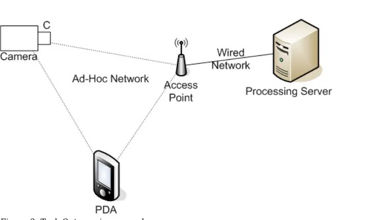
The example is illustrated in Figure 3. When the security guard's PDA comes within reach of an access point, it has a means of communicating with the processing server. Once the PDA detects that the processing server has spare processing power, it
transfers its context processing tasks to the server. The video streams from the cameras are directed through the access point and to the server, where they are converted to the PDA's format. The resulting data is sent back through the access point to the PDA, where it is displayed on the screen.
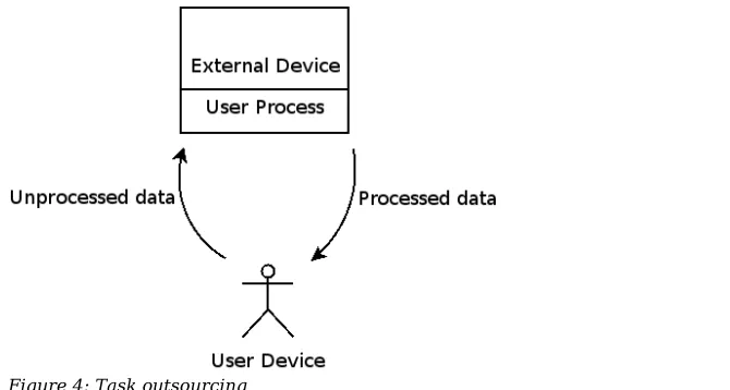
So, in more general terms, the user is walking in an area covered by an ad-hoc network. One of the user's portable devices is performing tasks, but for whatever reason is not able to perform them optimally. The device inquires on the ad-hoc network about other devices that can help it perform one or more of those tasks, effectively 'outsourcing' the task (illustrated in Figure 4). If the ad-hoc network has access to stable network
infrastructure such as the Internet it may try to contact known services for outsourcing. For the purpose of this scenario, we look at context processing as a task that can be outsourced.
Figure 4: Task outsourcing
An issue that arises in task outsourcing is trust. Can the application trust that the server converts data to the proper format without changing the contents? Can the server trust that the conversion code is safe for use? To allow this sort of distribution to happen, a certain level of trust must be ensured.
2.3 Scenario Emergency Situation
On the site of an emergency situation an ad-hoc network forms amongst the available devices installed in vehicles and carried by personnel. Context processing tasks that are performed by devices with limited resources, can move to a more powerful device as they join the network. This allows more and more costly processing tasks to be
performed as the network grows, which results in more and more detailed information. This information can feed medical applications that assist medical personnel in giving aid to patients on the scene.
In reality, the scenario might happen like this:
On a busy highway, a large traffic accident has happened with dozens of cars involved. A large amount of ambulances, police cars and fire brigade trucks speed to the scene of the accident. In such a calamity, the first doctors to arrive start to triage patients instead of treating them. They place basic sensor nodes on the casualties that monitor functions like ECG, blood pressure, et cetera. The doctors carry PDAs that can each monitor the output of a few sensors around them. As they move from one triage patient to another, sensor data from the last patient cannot be logged and is lost.
Fortunately, when ambulances arrive at the scene, the on-board computers form an ad-hoc network with the PDAs and sensor nodes so that the logging data can be passed on to the more powerful computers. There all data can be stored and analyzed.
When enough doctors and paramedics arrive to start treating patients, they can call up the known data about any patient that has been triaged.
When ambulances arrive at the scene, their on-board computers join the network. Those computers have more processing power and storage capacity than the PDAs. As soon as they join the network, they evaluate the current situation of the network, spot which sensor nodes are not being logged and start logging the data from a subset of them. Data from sensor nodes is grouped per person they are attached to, so that when the doctors start treating people they have an overview of the stored sensor data to evaluate. It is also possible that easy-to-interpret signals like ECG are automatically monitored, and if the signal indicates a problem such as a heart attack, the sensor immediately informs the doctors carrying a PDA.
3 Rule Distribution
The main issue of this project is how rules can be used to aid context processing in a distributed environment. In this chapter we discuss a method for doing this.
In section 3.1 we explain the concept of rules. Section 3.2 explains our approach to rule distribution. Section 3.3 explains why the decomposition process can be necessary and how it works. Section 3.4 shows how the decomposition process can be used.
3.1 Rules
In general, rules are used in information technology to describe a cause and effect, such as for example: “When enough heat is applied to ice, the ice melts”. The cause is a set of events and conditions that describe what state must hold so that the effect can happen. In our project, we assume that rules are described by an event, a condition and an
action. Whenever an event defined in a rule occurs and the condition of the rule is true, the corresponding action is performed. Events are generated by a system and can represent anything that is detected. The condition checks the state of the system. Consider the following example rule for an intelligent lightswitch:
If no-one is in the room for 5 minutes and the light is on, turn off the light.
In this rule, the event is “no-one is in the room for 5 minutes”, which would occur 5 minutes after the last person leaves the room. When this happens, the condition “Is the light on?” is checked. If this condition is true, the action performed is “turn off the light”.
An application rule is a rule that describes a combination of cause and effect that should occur in a system. There can be many applications supplying rules to the system and the set of all application rules together describe the system's behaviour.
Rules can be used in two ways: during development of a system to define what functionality the system should have so that it can be implemented, or at runtime to introduce or change behaviour in an existing system.
3.2 Approach to Rule Distribution
At the highest level of abstraction, a system is a single entity that interacts with its surroundings. The system's behaviour (or desired behaviour) can be described by a collection of rules that are composed of a set of events, conditions and corresponding actions. These rules are global and monolithic. They are global in the sense that they describe the system behaviour on the highest level and abstracting from the underlying network, and monolithic in the sense that each rule describes a distinct and unique aspect of behaviour.
For instance, a rule involving a sensor network may describe the storage of large amounts of sensor data, but a sensor node in the network has only limited capabilities and cannot store the amount of data required. However, there is a database in the network that can. So in order to allow the system to perform the behaviour defined in the rule, several devices in the network have to work together. What this means for the global rules is that they need to be broken down and translated into sub-rules for the different parts of the system before they can be assigned to those parts. This breaking down and translation of rules is performed in such a way that the resulting behaviour of the new set of rules when observed from the outside is the same as the original set of rules. In other words, if both systems are interpreted as a black box, they are
indistinguishable. Under these conditions, we call the process of creating the new rule set decomposition.
3.3 Rule Decomposition
As we described in section 3.2, it may be possible that rules written for an abstract system are not executable at a lower abstraction level in a distributed system. Rules must be decomposed and distributed over the system parts in order to be executed.
Definition: Rule decomposition is the act of transforming a set of high level rules for an abstract system to a new set of lower level rules for a system closer to implementation, so that the lower level ruleset defines the same observable behaviour as the high level rule set.
To illustrate why decomposition may be necessary, we use the example of a (fictitious) shipping company:
The shipping company “Jansen” located in the Enschede harbour has a large storage facility and ships cargo by truck from the harbour to anywhere in Europe. The storage facility has autonomous transport robots and a large automated administration system. The network of computers, robots, humans and cargo has become so large that making changes to how the system works is now a very complex and time intensive job. The IT department has recently decided to organize the system so that application rules can be used to describe how the system works.
The company has the following rule for their automated transport system:
When a customer declares that a crate is fragile, then attach a label to it and take extra care in packaging and moving the crate.
The rule above defines behaviour that the system should adhere to. However, in reality the system consists of a large network of devices with varying functionality; there are powerful computers like web servers that handle orders and servers that handle shipping information, but also autonomous robots that lift crates, truck drivers that require specific route instructions and even simple devices like the coffee machines or fire alarms. None of the parts of this system have all the functionality required to perform this rule, which means that if the shipping company wants the system to execute this behaviour, then the rule has to be decomposed into a more suitable form. One of the problems to be tackled in this decomposition is that not every system part may understand the concepts used in the rule. A robot picking up crates and putting them on lorries needs to know what 'extra care' means in its context. For the robot it may mean using a different set of grapplers, but for a truck driver it may mean driving only across paved roads. If the system is to use this rule, then the concepts in the rule must be translated to something that the different system parts can understand. Furthermore, the rule as a whole may include things that are irrelevant to parts of the system. For example, the labelling machine that has only one way of attaching labels to a crate does not need to know about 'extra care'. The crate-moving robot may need to know that it should read labels to see which crates require extra care, but it does not need to know anything about how to attach labels to crates and the cafeteria coffee machine has no need to know anything about this rule at all.
If we want to use a rule like the one above in a system, the rule must be decomposed into separate sub-rules and translated to the specific concepts relevant to each component of the system.
Rule decomposition can mean that the set of application rules becomes more complex. Suppose there is a second rule in the shipping company:
If a crate becomes damaged, inform the customer.
The examples above illustrate that in order to find the decomposition of a rule we need to look at what capabilities the rule requires, which system parts have these capabilities to offer, and what communication might be required to combine these capabilities into the desired functional behaviour.
3.4 Use of Rule Decomposition
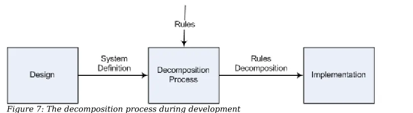
Like we said before in section 3.1, there are two ways in which rules can be used: during development and at runtime. Rule decomposition can also be used in these two ways. When used during development, a general description of what the parts will be able to do is used to decompose the rule (Figure 7). The result consists of several possible decompositions. Each of these decompositions then gives a possible distribution of tasks that, when implemented by the system parts, will execute the behaviour defined by the rule. Which of these decompositions is actually used can be narrowed down further by applying extra requirements to them. The final selection is then made by the system designers or programmers. If there are no possible decompositions, this means the given definition of the system does not have enough functionality to perform the rule.
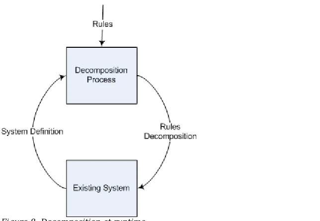
When used at runtime, the already existing system parts have precisely defined capabilities and those are used to find a decomposition of the rule (Figure 8). The resulting decompositions give possible ways in which the rule can be executed by the existing system parts, or when there are no possible decompositions this means that the system cannot execute the rule in its current form.
Because all the capabilities of the system parts are already known, it is possible to fully automate the decomposition and distribution process, potentially allowing it to be performed in real-time, as long as the decomposition process does not take too much processing power.
In Figure 9 we identify the input that is needed to perform the decomposition process:
The network topology is required in order to determine what communication is possible between the network parts. The topology can be automatically constructed, or in the case of development, supplied manually.
We need to know what the parts of the system can do, which sensors it has, which functions it can perform, et cetera. These capabilities are used in the decomposed rules. They can be supplied by the programmer, or each system part may have a way of
reporting its capabilities, which would allow this to happen automatically. And finally, we need a way of translating the abstract concepts used in the abstract rules to
concepts known to the concrete system parts. Some of these translations are common to most systems, and others will be specific to one system. The common translations can be supplied by a library and the specific translations must be supplied by the programmer.
Figure 8: Decomposition at runtime
4 Formal Definitions
This chapter provides the formal definitions for the decomposition process. In section 4.1 we introduce a formal definition of the rule language used in this project. In section 4.2 we give the formal definition of a system and in section 4.3 we formally define the decomposition process.
4.1 Rule Language
In this report we use a rule language to express rules. It uses the Event-Condition-Action format:
Rule: EventCondition→Action
In this notation, “” separates the Event and Condition statements. If the event expression and the condition expression both evaluate to true, then the actions are performed.
It is not required that a rule has a condition, i.e. it may be possible that the event itself is enough to trigger an action. In such a case, the condition expression can be a simple
true statement. Because adding 'true' to each rule without a condition is not necessary to understand the rule, it can be left out, which simplifies the rule to:
Rule: Event→Action
The rule for damaged cargo from the shipping company example in section 3.3 can be represented in the rule language as:
R1: DamagedCargoDetected(Crate c) → InformOwner(c)
In this rule, c is a variable generated by the event. Variables are explained later in section 4.3.1.
To allow the decomposition process to be automated, it is necessary to formally define it. In addition to the format defined above, we also introduce a formal notation to represent rules.
4.2 System Definition
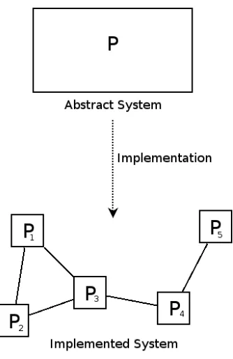
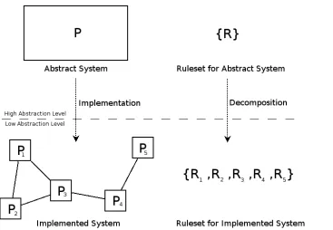
Before decomposition, we consider an abstract high-level system with its behaviour defined as a set of abstract, high-level rules. In reality, when the system is implemented, it consists of a set of system parts connected by a network, which was illustrated by Figure 5. The implemented system is on a lower abstraction level than the abstract system.
We give a formal definition for a system in order to use this definition in the description of the rule decomposition process.
Definition: Any system is a directed graph consistin of a set of system parts L and a set of edges G.
The definitions of these terms are given below:
Definition: The set of system parts L contains the individual system parts that make up the nodes in the communication graph of the system.
L
⊆
system parts
These system parts can be devices, but they can also be networks, groups of devices or types of devices. If a system part is not a device but a network, group or type, the rule set that is assigned to it by the decomposition process can be decomposed further by another iteration of the decomposition process. In the next iteration, this system part becomes the abstract system and the decomposed rule assigned to this system part becomes the abstract rule.
Definition: G is the set of edges. G contains an edge between two nodes if and only if there is a means of direct communication between the corresponding system parts.
G
⊆
L
×
L
There is a means of direct communication between two nodes if they can communicate with each other directly through the lower level communication protocol. For example, if two computers are on the same IP network, they have a means of direct communication through the TCP/IP protocol.
Edges can have constraints that include the communication properties and direction. The properties can define the protocol, what sort of data can be sent, how expensive it is to use the communication link, et cetera.
The abstract system in Figure 5 would be defined as L = {P} and G = {}. The
implemented system would be defined as L = {P1, P2, P3, P4, P5} and G = {(P1, P2), (P1,
P3), (P2, P3), (P3, P4), (P4, P5)}.
4.3 Decomposition Process
We now formally define the decomposition process.
Definition: An abstract rule set R is defined as a set of rules for an
abstract system. Each rule in the set consists of terms E, C and
A where E is a logical expression containing events, C is a logical expression containing conditions and A a list of actions.
R={
R
n: E
C
A
}
To perform the decomposition process, some more attributes have to be defined for the implemented system: We need to know what capabilities parts in the system have or will have, and how to translate concepts in the rule from concepts for the abstract system to concepts for the implemented system. These attributes are called the properties of the system.
4.3.1 System Capabilities
System parts have functions they can perform that are defined as a list of capabilities. In an existing system, these capabilities will be very precisely defined so that a resulting decomposition can be directly assigned to the system parts, but in a system in
developmen, they will be more general and abstract; the resulting decomposition will then tell the developer which system part should implement what functionality.
Definition:S is a mapping of capabilities to system parts that have those capabilities. Capabilities are defined as events, conditions, actions and functions.
capabilities
=
events
∪
conditions
∪
actions
∪
functions
S
⊆
system parts
×
P
capabilities
It is possible that multiple system parts have the same capability. Capabilities can be four diffent things:
1) Events represent things that have happened in the system. An event may contain information about the occurance, or it may just be a token. When we say that a system part has the capability for an event, we mean that it has the capability to detect such an event.
2) Conditions are generally tests of system states, or system states in the context of event information. If a system part has a condition as a capability, it means that it can check that condition.
3) Actions are generally system procedures that execute a task.
4) Functions are operations or calculations that can be required as part of event or condition expressions, ranging from simple logical operations to complex tasks and math calculations.
Data that accompanies an event can be accessed through a variable. The variable originates from the event and can be used in functions, conditions and actions.
The most commonly used functions are the logical operators and,or and not. They can be used to combine events and/or conditions.
Besides logic-calculation functions, most system parts also have the capability to send and receive messages to and from other system parts that they are connected to. Which parts they have contact with is defined in the system definition. This capability is also assumed to be present on all system parts unless specifically stated otherwise.
4.3.2 Concept Translation
The abstract rules are often written without knowledge of the details of the implemented system. Such rules use terms to describe abstract concepts that the implemented system may not necessarily undertand. In order to decompose these rules we have to bring these concepts to a lower level of abstraction. To do this, we need a function that translates abstract concepts to concepts that the lower level system can handle.
Definition: T is a function that translates a set of rules to a new set of rule sets.
T
old rule set
=
set of new rule sets
In this definition, the rule sets are subsets of the set of all possible rules.
In the example of the lightswitch in section 3.1 the action “turn off the light” could be an abstract concept. If the actual room contains three lamps, T will translate this concept from “turn off the light” to “turn off lamp 1, turn off lamp 2 and turn off lamp 3”.
When T is implemented, the function is represented a set of tuples (rule, rule) where the first rule is any of the rules from the incoming rule set and the second is rule is the new rule that should replace it. T results in new possible rule set translations, in addition to the original. So when the set of tuples in T is empty, then T(r) = {r}. If T contains a single translation from r to r' then T(r) = {r, r'}.
T
⊆
rules
×
rules
In this definition, rules is the set of all possible rules.
For example: T could define a mapping like the following example of a doorbell in a store:
customer entering store
sound bell
⇒
doormat detects person
play bell sound
We use ⇒ to distinguish between the old rule and the new rule. However, such a direct mapping as this will not be encountered very often. Often we need a partial mapping that only changes part of the rule, like this one for the intelligent light switch example:
∀
a
∈
events ,
∀
b
∈
conditions :
a
b
Turn off the light
⇒
a
b
Turn off lamp
1
∧
Turn off lamp
2
∧
Turn off lamp
3
In this case, events is the set of all possible events and conditions is the set of all possible conditions. In a similar way we can write a partial mapping for actions and
functions.
As a short-hand, we will write the above rule mapping like this:
When applying a translation to a rule, the result may be more than one rule. In that case, the mapping results in a set of rules like this:
cust.entering
sound bell
⇒
{
doormat detects person
play bell sound
doormat detects person
∧
store is empty
send notif. tomanager
}
The transformation rule to translate one concept to another can become very
complex,because all possible uses of the concept have to be addressed. As a shorthand for such a large translation, we describe in textform how one concept can be translated to another, like in the following example:
translate the concept
Patient
to the concept
Tag
with
an additional condition :hasRole
Tag
,
PatientRole
4.3.3 The Decomposition Algorithm
Now that we have the definitions needed to decompose a rule set for an abstract system to a rule set for a lower level system, we will define the algorithm. We have the
definition of the lower level system (L,G), the definition of the rule set R and the
properties of the system (S,T). The abstract rule set R is then decomposed to a valid rule set for the implemented system.
Definition: Given a rule set R with n rules and a low level system (L,G)
with properties (S,T), the decomposition process is defined as a function that decomposes R into Rd.
R
d=
Decompose
R
, L , G , S , T
Decompose
R
, L , G , S , T
=
{
D
L , G , S ,T
R
0
, D
L ,G , S , T
R
1
,...
,
D
, L ,G , S , T
R
n−1
, D
, L ,G , S ,T
R
n
}
In this definition, T(r) is the application of the translation mappings to r. The function D
decomposes a single rule.
When implemented, D(L,G,S,T(r)) works like this:
(1) For each resulting rule set from T(r), find a match for the events, functions and actions in the rules in the capability list S. When an event, condition, function or action can be executed by more than one system part, this results in multiple matchings. Each of these matchings results in a new possible decomposition rule set.
(2) Construct a directed graph for each rule set from (1) (we explain below how a directed graph for a rule can be constructed).
(3) For each graph, determine the required communication and find a path in (L,G)
between each pair of system parts in the required communications.
(4) For each communication path found in (3), apply sending action and receiving event substitution in the results of (1) corresponding to the graph from (2), so that there is a rule for each node in the path.
A pseudo-code representation of the algorithm can be found in section 6.2.3.
A rule has a basic order in which it must be executed; the events and the conditions must be true before the actions are performed. But beyond that, no execution order is defined. To support the decomposition process, we have defined a specific order in which a rule is executed, so that the communication choices can be made: when the events in a rule occur, first the event expression is evaluated. If this expression holds true, the condition expression is then evaluated. If this is also true, the actions are executed in the order that they have been defined.
The directed graph mentioned in step (2) illustrates the flow of execution of a rule (see example in Figure 11). It is used to determine what communication is required and how to break up a rule when it must be partially executed on different system parts.
The graph is formed by starting with a tree graph for the event expression. The events are the end nodes and the functions that combine them form the branches. Another tree graph is formed for the condition expression and one for the actions. The tree graphs are then connected; the top of the event graph connects to each end node of the condition graph and the top of the condition graph to the bottom of the action graph. As an example, consider the following rule:
E
1∧
E
2
C
1∨
C
2
A
1, A
2The directed graph in Figure 11 shows the flow of execution for the rule. If we then assign system parts to perform parts of the rule, we can immediately determine what communication is required.
Figure 11: Directed graph.
If R is the rule set before translation and Rd the rule set after, then R and Rd must have
equivalent observable behaviour. When looking at the system with the rules as a black box, the observed behaviour should be the same before and after the translation.
The decomposition algorithm changes the contents of the rules in two positions: during the translation phase and during the substitution of communication events and actions. This demand for equivalency is put on both the translation table and the communication substitution. Each translation step in the translation table must yield the same
4.4 Examples
In this section we give three examples: An example showing a simple transformation of a rule, an example that shows alternative decompositions of a rule and an applied example from the elderly home scenario.
4.4.1 Simple Transformation
This example describes a simple system with two parts x and y, that can communicate directly. Part x can detect event E and part y can perform action A. For this system, we have a rule that describes that whenever E occurs, A should be performed. Through the application of some simple steps, the example explains how the rule can be decomposed so that there is a rule for x and a rule for y which only contain expressions that can be performed locally on x and y respectively.
Figure 12: example system
For this simple example no translation is necessary, which means that T is empty. If we represent the example above in the formal definitions, it looks like this:
The system definition:
L
={
x , y
}
G
={
x , y
}
The system properties definition:
S
={
x ,
{
E
}
,
y ,
{
A
}}
T
=∅
The rule set defininition:
R
={
R
0}
R
0: E
A
(1)Now we perform the decomposition algorithm on R so that it can be executed by the system.
At first we should apply the translation steps in T to R, but because T is empty, we can skip this phase and continue. Next we try to match the conditions and actions used in R
to S. This is possible, because x has capability E and y has capability A. We then rewrite (1) to include this information:
R
0': E
x
A
y (2)Now that we know that x and y are involved in this rule, we look at G to see if x and y
can communicate. That is possible because there is a direct path from x to y. Because the path contains two different system parts, the result of rewriting (2) becomes a rule set consisting of two rules: one for system part x and one for system part y:
If we consider (2) in the context of x, we conclude that the event can be handled locally, but the action can not. According to the path we found in G communication with y is possible, so for Rx we rewrite the action Ay as an action S that sends communication to
part y with the event as a parameter:
R
x: E
S
y
E
(4)The action Sy(E) sends a message to y concerning E.
Similarly, if we consider y we conclude that the action A can be performed locally, but the event can not. According to the path found in G we can expect incoming
communication from x, so for Ry we replace Ex with an event R that receives
communication from x with the parameter E:
R
y: R
x
E
A
(5)The event Rx(E) occurs when a message is received from x concerning E.
Rules (4) and (5) can be performed locally on x and y, respectively. Rule sets R and R''
describe the same observable behaviour, but where R describes the behaviour for the whole system, R'' describes the behaviour for each system part. R'' is the decomposition of R for this system.
4.4.2 Transformation with Alternative
Decompositions
Consider a system with four parts connected as shown in Figure 13:
L
={
x , y , z , q
}
G
={
x , z
,
y , z
,
z , q
}
With the properties:S
={
x ,
{
E
1}
,
y ,
{
E
2}
,
z ,
{
'
∧
'
}
,
q ,
{
A , '
∧
'
}}
T
=∅
We want to decompose the rule set R:
R
={
R
0}
R
0: E
1∧
E
2
A
This example shows logic in the event clause in the form of the and ('Λ') function. From S we conclude that both system parts z and q can perform this function. T is empty, so the translation step does not change the rule set.
Starting the decomposition process, we can match R to S:
I :
R
0'
: E
1x∧
zE
2y
A
qII :
R
0': E
1x∧
qE
2y
A
qBecause the and function can be executed by both z and q, two decompositions are possible. We first look at decomposition I:
R
0': E1
x∧
zE
2y
A
qBecause this rule involves several system parts that must communicate, the explanation of how the decomposition works requires some more intermediate steps than the last example.
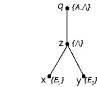
First we construct a directed graph that shows the flow of execution (Figure 14).
We construct this graph to see if and what communication is required. It shows that in order to execute Aq in the rule, the and function must be evaluated first, which depends
on the events E1 and E2. From this we can conclude that communication is required from
x to z, from y to z, and from z to q.
We can then use the same substitution with sending actions and receiving events as in the first example to arrive at the following decomposition:
Decomposition I :
R
x: E
1
S
z
E
1
R
y: E
2
S
z
E
2
R
z: R
x
E
1∧
R
y
E
2
S
q
E
1∧
E
2
R
q: R
z
E
1∧
E
2
A
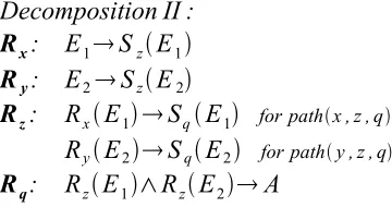
Similarly, we can construct a tree for the second decomposition (omitted) and determine that communication is required from x to q and from y to q. This leads to the following end result:
Decomposition II :
R
x: E
1
S
z
E
1
R
y: E
2
S
z
E
2
R
z: R
x
E
1
S
q
E
1
for pathx , z , qR
y
E2
S
q
E
2
for pathy , z , qR
q: R
z
E
1∧
R
z
E
2
A
We can observe from the amount of sending actions in both I and II that the first decomposition requires less use of the network, but we can also see that the second decomposition requires less calculation by the connecting system part z. Which of these decompositions would be used depends on what additional requirements have been defined for the decomposition of R.
Multiple decompositions of a system can be possible because of similar capabilities found in S or because of multiple possible translation steps in T. In the above example, both z and q can execute the and function, so two decompositions are possible. If we would specify that all nodes can perform the and function, that would lead to four possible decompositions.
4.4.3 Elderly Home Example
This example involves a simplified system for the elderly-home scenario. We assume the availability of sensors that can detect people, a server application that can retrieve information from a database and contact people, a database that can forward messages and a gateway that has a connection to the sensor network and can write data into the database. For the example we look at a rule that describes the following behaviour:
When a patient is detected in a restricted zone, close the door in that zone.
If we represent this rule in our rule language, it looks like:
Detected
Patient
LocatedIn
Patient , RestrictedZone
CloseDoor
RestrictedZone
This top-level rule describes the system's behaviour. The system is defined as follows (Figure 15):
L = { server application, restricted sensor nodes, allowed sensor nodes, gateway, database
}
S = { (server application, {HasRole, logic functions}),
(restricted sensor nodes, {DetectTagRestricted, CloseDoor}), (allowed sensor nodes, {DetectTagAllowed})
}
Figure 15: Graph G. The database forms a necessary router between the server application and the gateway, which is imposed as a restriction by the technology used (see Appendix A).
T = {
Translate “Patient” to “tag” with an extra condition “hasRole(tag,PatientRole)”,
Detected
tag
LocatedIn
tag , RestrictedZone
∗ ⇒
DetectTagRestricted
tag
∗
,
DetectTagRestricted
tag
∗
CloseDoor
RestrictedZone
⇒
DetectTagRestricted
tag
∗
CloseDoor
}
means that the rule cannot be executed by a single device and decomposition is required.
Given the definitions above, we now apply the decomposition process on the rule. First we use the translation table T. When the translations steps are applied, the following rule is generated:
DetectTagRestricted
tag t
hasRole
t , PatientRole
CloseDoor
Next we construct a tree diagram from this rule, as shown in Figure 16:
Because hasRole is a function that uses a variable t that originates from event
DetectTagRestricted, communication is required to allow the function to use t. In other words, the result of DetectTagRestricted has to be sent to the hasRole function. If the
hasRole function then evaluates to true, the action closeDoor can be performed. As we can see from Figure 16, this involves communication from restricted sensors to the server application and from the server application to restricted sensors.
When the communication from the tree diagram is expressed in sending and receiving actions, the following rule set is generated:
Restricted sensors:
DetectTagRestricted
tag t
send
DetectTagRestricted
t
to gateway
Receive
CloseDoor
from gateway
CloseDoor
Gateway:
Receive
DetectTagRestricted
tag t
from restricted sensor
send
DetectTagRestricted
t
to database
Receive
CloseDoor
from database
send
Detected
tag
to restricted sensor
Database:
Receive
DetectTagRestricted
tag t
from gateway
send
DetectTagRestricted
t
to server application
Receive
CloseDoor
from server application
send
Detected
tag
to gateway
Server application:
Receive
DetectTagRestricted
tag t
from database
hasRole
t , Patient
send
CloseDoor
to database
The rules assigned to the restricted sensors are assigned to the whole group of sensors. In this example, the decomposition ends here. In an actual implementation, further decomposition on these rules may be required for the group of sensor nodes to arrive at rules that can run on each individual sensor.
The resulting decomposition is not very efficient, since every time a tag is detected by a sensor in a restricted zone, it must inform the server, because only the sensor can check if the detected person is a patient. If the sensors had the capability to perform (part of) the hasRole function, far less messages would have to be sent over the network.
5 Applying Rules to the Scenarios
Using the definitions from the previous chapters, it is possible to apply the rules approach to the problems defined in the scenarios. First we discuss how rules and rule decomposition affects the elderly home scenario, which is the basis for the prototypes. We consider requirements, the user interactions and the rules that we can derive from the scenario. Then we will define an architecture for the system. Following that we will discuss how rules affects the other two scenarios. At the end of this chapter we discuss the architecture of the middleware that supports rule decomposition.
The required system posed in the elderly-home scenario (section 2.1) can be developed with a rules-based approach. To do this, we need to define the architecture for the system and the abstract rules that define the system behaviour, and then decompose those rules. The resulting rule set can then be implemented to arrive at the working system. In this section we will discuss the requirements, user interactions, rules and architecture. The decomposition is discussed with the implementation in chapter 6.
5.1 Requirements
First, we consider the requirements that we can derive from the Elderly Home scenario. The abstract rules are directly based on these requirements. The following requirements can be identified in the scenario:
Tracking of location
The scenario defines the following system requirement:
“To track people in and around the home, to use this tracking information to decide whether a patient has wandered off and to generate an alarm message to caregivers in the ward.”
The main function of the system will be to determine if patients are in areas they are allowed to be in and to track their movement if necessary. If a patient enters an area that they are not allowed to enter without a caregiver or visitor as a guide, the system needs to check if there is a guide and inform the caregivers with a message if there is not. The administrators divide the building into three different types of zones, that are used by the system. These areas consist of admissable zones (green), non-admissable zones (red) and admissable zones close to non-admissable zones (yellow).
Daycare room
“Part of the ward is a daycare room, which is a large recreation area where patients walk in and out all day. A caregiver must be present in the daycare room at all times as long as there are patients present. The administration wants an indicator to be visible somewhere in and around the daycare room that shows if it is unattended or when the last caregiver leaves the area while patients are still present.”
This requirement is already literally defined in the scenario. The indicator is a set of lights placed inside and outside of the daycare room, that can be turned on and off using an electronic switch.
Privacy
The system should ensure the privacy of the patients whenever possible. Interceptable communication that contains privacy sensitive information should be kept to a minimum. Location information of patients is considered privacy sensitive information.
Smart door
“The main entrance door to the ward is a special location. This door has an electromagnetic locking mechanism, which needs to be turned on when a patient approaches the door from inside without guidance.“
The system needs to provide the door with instructions to open or close the lock depending on the proximity of patients and caregivers.
The following requirements are not explicitly stated in the scenario, but can be derived implicitly:
Privacy exceptions
It should be possible to disable the privacy protection, in an emergency situation (e.g. a fire) when it is highly desirable that the location of all patients can be quickly
determined. It is also possible that a patient is carrying some sort of healthsensor to monitor a medical condition that can detect an alarm situation, if such a situation happens then location data of this patient should be available immediately. Only certain people should be allowed to declare an emergency situation like this, and only certain people should have access to the location data.
Technology
To make this system work, a technology is required that is able to track people in the home with a minimum amount of invasiveness. Practice has shown that a technology with too much invasiveness such as a bracelet or an ankle strap is not accepted by the patients and they will then spend a lot of time trying to remove such technology. One possible technology, which is the technology used in the prototypes, is that of sensor networks and is described in Appendix A.
Status messages
Depending on the technology used, indication messages need to be sent to administrators when a sensor or tag that is running on batteries expects to be unavailable soon, because e.g. its power is low.
5.2 User Interactions
This section discusses interactions that users can have with the system. We use those to identify some technology-related requirements for the system.
Figure 17: Patient interactions.
Patient interactions with the system (Figure 17):
• The system registers that a patient walks around carrying a tag.
• The system registers that a patient enters a green area. • The system registers that a patient enters a yellow area. • The system registers that a patient enters a red area.
The system should be able to determine in what type of area a patient is moving, and depending on the situation, track the location or take certain actions.
Caregiver interactions with the system (Figure 18):
• The system registers that a caregiver walks around carrying a tag and a mobile receiving device.
• A caregiver receives a warning message that a patient has entered a red area unsupervised.
• A caregiver receives a warning message that there is no caregiver in the daycare room.
The system should be able to track the location of a caregiver and send messages to them.
Visitor interactions with the system (Figure 19):
• The system registers that a visitor walks around carrying a tag.
A patient guided by a registered visitor should not trip an alarm when entering a red zone. This requires the system to keep track of the location of visitors.
Administrator interactions with the system (Figure 20): • An administrator changes the list of patients.
• An administrator changes the placement or classification of an area (green, yellow or red).
New patients move into the ward as older patients pass away or move to other wards. The system should allow changing the list of patients and propagate this change to the whole system. The system should also allow changing the placement or the classification of areas and propagate this change to all the nodes in the network.
Figure 18: Caregiver interactions.
Figure 19: Visitor interactions.
Door lock interactions with the system (Figure 21): • The system tells the door lock to close. • The system tells the door lock to open.
The door lock on the ward entrance door can be triggered electronically, the system needs to tell it when to open or close.
Indicator light interactions with the system (Figure 22): • The system tells the indicator lights to turn on. • The system tells the indicator lights to turn off.
The indicator light in and around the daycare area can be triggered electronically, the system needs to tell the lights to turn on or off.
5.3 Rules
The requirements can be used to derive a set of rules that define the system's required functionality.
The following rules have been defined regarding the location tracking requirement:
When a patient enters a red zone and that patient is not guided, sound an alarm to all caregivers.
When a patient enters a yellow zone with a door and that patient is not guided, lock that door.
Regarding the daycare indicator requirement:
When a patient is in the daycare room without a caregiver present, turn on the indicator.
When a caregiver enters the daycare room and the indicator is on, turn off the indicator.
Regarding the system administration:
When an administrator changes the zones or the patient list, update the proper definitions in the system.
The privacy requirement does not translate into a set of rules, but rather into a requirement for the rule decomposition. When the sensor network sends detection
Figure 21: Door lock interactions.
messages about a tag out to the gateway, this is personal information that can be intercepted. So if possible, the decomposition that has the minimal amount of message exchanges concerning location sent via the sensor network should be selected.
5.4 Architecture
Figure 23 shows the interaction of people and 3rd party components with the system and
identifies four internal system parts:
1) A sensor network detects tags belonging to patients, visitors and caregivers. The nodes in the network can send data to the gateway.
2) The gateway can process