The International Linear Collider
Benno List1,a
1Deutsches Elektronen-Synchrotron DESY, D-22603 Hamburg, Germany
Abstract. The International Linear Collider (ILC) is a proposede+e−linear collider with a centre-of-mass energy of 200–500 GeV, based on superconducting RF cavities. The ILC would be an ideal machine for precision studies of a light Higgs boson and the top quark, and would have a discovery potential for new particles that is complementary to that of LHC. The clean experimental conditions would allow the operation of detectors with extremely good performance; two such detectors, ILD and SiD, are currently being designed. Both make use of novel concepts for tracking and calorimetry. The Japanese High Energy Physics community has recently recommended to build the ILC in Japan.
1 Introduction
For more than 50 years,e+e−colliders have been a indispensable tool in high-energy physics, at which important particles such as theJ/ψ, theΥ, theτlepton and the gluon were first observed and the properties of theW±andZ0gauge bosons were studied at unprecedented detail, establishing today’s Standard Model of elementary particle physics. The recent discovery of a new, Higgs-like boson with a mass around 125 GeV at the LHC sets the scale for the next generation ofe+e−colliders that will be used to make precision measurements of the properties of the top quark, the Higgs boson and their interactions.
Within a few years after the firste+e−colliders came into operation Maury Tigner realized [1] that the energy losses due to synchrotron radiation ine+e−storage rings would become prohibitive at very high beam energies, at which point linear accelerators would be the more economic alternative. For at least two decades it has been a widespread consensus among accelerator physicists that a machine with a centre-of-mass energy significantly exceeding the 209 GeV achieved at LEP-2 would have to be linear [2]. More than 20 years of research and development into the technology to build and operate such an accelerator based on superconducting RF technology, the International Linear Accelerator, have since passed.
2 The International Linear Collider
In 2003 a panel chaired by Rolf-Dieter Heuer defined that the next lineare+e−collider should be able to reach a centre-of-mass energy of 500 GeV, tunable down to 200 GeV, with the possibility to up-grade to 1 TeV [3]. It would be capable of delivering an integrated luminosity of 500 fb−1at 500 GeV within a four year period, which would demand an instantaneous luminosity around 2×1034cm−2s−1.
ae-mail: [email protected]
DOI: 10.1051/ C
Owned by the authors, published by EDP Sciences, 2014 /2014 00 07 0
The accelerator should achieve electron polarization above 80 %, with positron polarization up to 60 % if possible.
In 2004, the International Technology Recommendation Panel [4] reviewed several accelerator projects from America, Asia and Europe that fulfilled these parameters and chose the technology using superconducting RF cavities of the European design TESLA [5] as basis for the design of the International Linar Collider (ILC). One year later, institutions from all around the world founded the Global Design Effort (GDE), which in 2007 produced the ILC Reference Design Report (RDR) [6] and an intermediate report in 2011 [7] and will conclude its activities in 2013 with the publication of the ILC Technical Design report TDR.
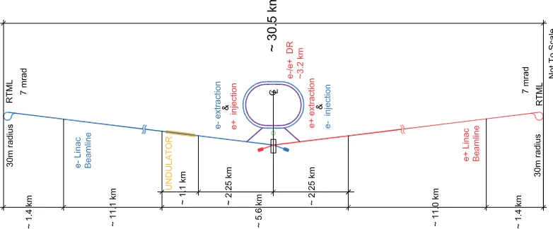
The overall layout of the ILC is shown in Fig. 1, and its main parameters are listed in Tab. 1. In the following, a brief outline of the physics case for the ILC is given, before the accelerator and the detectors are presented. The prospects for a realization of the ILC are discussed in the last section.
Figure 1.Layout of the ILC.
3 The Physics Case for an e
+e
−Linear Collider
The discovery of a new, Higgs-like boson with a mass around 125 GeV at the LHC collider [9, 10] confirms the argument for ane+e−Linear Collider that has been brought forward since more than ten years, namely that such a machine would be an ideal Higgs- and top factory. This physics case alone ensures a rich physics harvest [11, 12]. ILC would thus be in a similar situation as LEP was in its time and increase our knowledge of the Standard Model by high-precision measurements. In addition, as any collider that raises the available centre-of-mass energy compared to its predecessors, the ILC would have an interesting discovery potential for physics beyond the standard model.
3.1 Characterizing the Higgs Boson
Table 1.Parameters of the ILC [8]
Parameter Baseline L Upgrade E Upgrade B Unit
Maximal center of mass energy 500 500 1000 GeV
Luminosity at max. energy 1.8×1034 3.6×1034 4.9×1034 cm−2s−1
Polarizatione−/e+ 80/30 80/30 80/22 %
RF Frequency 1.3 1.3 1.3 GHz
Average accelerating gradient 31.5 31.5 31.5/45 MV/m
Particles per bunch 2 2 1.74 1010
Bunches per pulse 1312 2625 2450
Bunch spacing 554 366 366 ns
Repetition rate 5 5 4 Hz
RMS beam size at Int. Point (hor.×vert.) 474×5.9 474×5.9 335×2.7 nm×nm Norm. emittance at Damping Ring (hor.×vert.) 5.5×20 5.5×20 5.5×20 μm×nm Norm. emittance at Int. Point (hor.×vert.) 10×35 10×35 10×35 μm×nm Beta function at Interaction Point (hor.×vert.) 11.0×0.48 11.0×0.48 11.0×0.23 mm×mm
Total beam energy 10.6 21.0 27.6 MW
Facility electrical power 161 204 299 MW
and bosons of the Standard Model, and proof of the self-coupling. Precision measurements of the couplings will also help to determine whether the Higgs has the properties predicted by the (mini-mal) Standard Model, with a single Higgs couplet, or whether two doublets are needed as predicted by SUSY models, or whether much more exotic states such admixtures from Radions are needed to explain this boson’s properties.
There is no doubt that LHC will accumulate an enormous amount of data pertaining to these ques-tions before any Linear Collider will become operational. It has also been observed that a Higgs mass of 125 GeV leads to a situation where the Higgs is expected to decay into many different states with measurable probability; while making the discovery more difficult, because so many decay channel have to be investigated, it will lead to a very rich physics harvest, because all these channels can be investigated. Nonetheless, the clean environment of ane+e− collider, with the possibility to adjust (and know) the energy, momentum and spin of the initial state, is hugely beneficial for several key measurements.
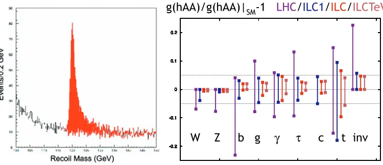
A scan of the production threshold of the processe+e−→Z0hat 215 GeV CME would determine unambiguously the spin and parity of the new boson, along with a very precise mass measurement. About 20 GeV above threshold, at around 235 GeV CME, the production cross section in theZ0h is maximal. At this energy, a unique measurement would be performed: the determination of the absoluteZ0hcoupling by a recoil mass measurement in the processe+e−→ Z0h. Here, the leptons of theZ0decays toe+e−andμ+μ−are utilized to measure the invariant mass of the stateh, whithout using any decay products of this state. From the recoil mass spectrum (see Figure 2 left), the totalZ0h production cross section and thus the absoluteZ0hcoupling can be determined.
:=EJ
G
T
FWLQY
JK$$JK$$_
60/+&
,/&
,/&
,/&7H9
Figure 2.Left: Recoil mass distributions in the SiD detector in thee+e− →μμhchannel for a 120 GeV Higgs, assuming 250 fb−1 luminosity. The signal in red is added to the background in white [13]. Right: Estimated
accuracies of Higgs coupling measurements for LHC at 14 TeV with 300 fb−1, for ILC at 250 GeV and 250 fb−1
(‘ILC1’), for the full ILC program up to 500 GeV and 500 fb−1 (‘ILC’), and for a program with 1 ab−1for an
upgraded ILC at 1 TeV (‘ILCTeV’) [14].
and operate detectors based on technologies such as gaseous time projection chambers or extremely thin silicon pixel detectors, which can deliver unprecedented performance, but would be impossible to operate in the much more challenging environment of a hadron collider, as will be discussed below. In fact, the Higgs recoil mass measurement drives the targeted momentum resolution of the tracking detectors.
Further measurements of the Higgs branching fractions would benefit from a higher centre-of-mass energy, around 350 GeV, because the resulting boost would be beneficial for the tagging of the final state; at the ILC, even the branching fraction to charm, beauty and invisible decay products will be measurable with to better than 5 % (Figure 2 right).
Even higher energies above thet¯ththreshold at 475 GeV will allow a direct measurement of the t¯thcoupling, which is not accessible through branching ratio measurements. A scan of the threshold itself will show whether the Higgs is purely CP-even, or whether small CP-odd admixtures are present [15]. The final, Litmus test of the Higgs mechanism is the establishment of the Higgs self coupling through the processe+e−→Z0hhwith a threshold of 340 GeV. A 5σobservation of this process will probably be possible only at centre-of-mass energies above 500 GeV.
To summarize, a complete characterization of the Higgs boson’s properties requires a cleane+e− collider with a centre-of-mass energy (precisely) tunable between 215 and 500 GeV or more, which is precisely the charge given to the Global Design Effort in 2003 by the “Heuer panel” [3].
3.2 Electroweak precision physics
In the early nineties of the last century the first precision measurements from LEP made it possible to deduce the top mass from its loop corrections to electroweak observables, which are proportional tom2
fact, the Higgs has now been discovered, this pattern can be repeated. This time, radiative corrections from physics beyond the Standard Model will be measured.
Two masses, those of the W boson and the top mass, are of central importance to this program. Both can be measured with excellent experimental precision at hadron colliders. However, mass reconstruction from the invariant mass of final state particles is invariably1subject to significant QCD corrections, even at lepton colliders. For the top, these uncertainties have been estimated to be of order 1 GeV, significantly larger than the experimentally possible precision, with little hope of dramatic reduction. A threshold scan, however, is free from these theoretical problems, and provides data that can be linked to the underlying theoretical mass parameters with a much smaller uncertainty. Thus, a top pair production threshold scan at 350 GeV CME, and possibly a W pair threshold scan at 160 GeV (though this is technically outside the baseline range of the CME, it will most probably be feasible), would constrain any physics beyond the Standard Model with much increased precision. The top mass could be determined with a statistical accuracy of∼27 MeV [16], the width with 22 MeV accuracy [5].
A possible extension of the physics program, although not part of the baseline, would be “Giga-Z,” where the ILC would run on the Z-pole and accumulate not only about a hundred times more Z events than LEP, but with polarized beams and flavor tag capabilities far beyond those of the LEP era. This would permit to improve the asymmetries measurements of LEP and SLC by a large factor and again provide stringent constraints on any model of new physics, whether new particles of such models will have been discovered at LHC or not.
3.3 The discovery potential
At 500 GeV CME, the ILC will more than double thee+e− energy of LEP, at a hundred times the luminosity. Such a machine will have a considerable discovery potential, which would be nicely com-plement the LHC running at 14 TeV [17]. Although it is by no means the only viable theory beyond the Standard Model, I will in the following focus on Supersymmetry (SUSY for short) to discuss that potential. Different arguments that have been put forward why SUSY particles should be “light”, i.e. in the (several) 100 GeV range: there is the naturalness argument, namely that SUSY partners are needed to cancel the radiative corrections to the Higgs mass, in particular from the top loops, which means that the 3rd generation squarks should not bee too heavy. Also some measurements which are difficult to reconcile with SM predictions, such as that of the muong−2, could find an explanation if some particles were light, in this case the smuon. These and similar arguments favour relatively “light” leptons, 3rd generation squarks, and partners of the electroweak gauge bosons (“electroweaki-nos”). If any of these particles would be kinematically accessible at the ILC, they would be produced copiously and cleanly, and that includes scenarios which may be hard or impossible to observe at LHC, for instance if some particles have masses close to the mass of the Lightest Supersymmetric Particle (LSP) (known as “compressed spectra”).
1st and 2nd generation quarks and gluinos, on the other hand, which would be copiously produced at LHC, contribute little to the radiative corrections of the Higgs mass or the muong−2, and could very well be heavy, i.e. in the multi-TeV range. In some models such as the CMSSM, which make assumptions about a possible mass unification at high energies of the gauginos or sfermions, already the non-observation of SUSY particles in the earliest LHC data was taken as indication that SUSY particles would be too heavy for ILC to observe. In more general models such as the Parametrized MSSM (PMSSM), with their broader set of parameters, such conclusions are not valid, because there
the strongly interacting sector of the SUSY particle spectrum could be much heavier than the color-neutral sector [17].
4 The Accelerator
The two most prominent parameters of a high-energy particle collider are its centre-of-mass energy √
sand its luminosityL; thus, the two most important problems are to accelerate the beam, making optimal use of the available electrical power and space (i.e., tunnel length), and to focus the beams in a sufficiently tiny spot. The ILC is based on superconducting radio frequency (SCRF) cavities. Producing beams of sufficient intensity and quality is a challenge, in particular for the positrons. Focussing the beams in a beamspot of 639×5.9nm2size requires to concentrate the beam particles very densely in phase space, which needs advanced damping rings, and a highly sophisticated final focus system that demagnifies the beams and brings them into collision. These aspects are discussed in the following.
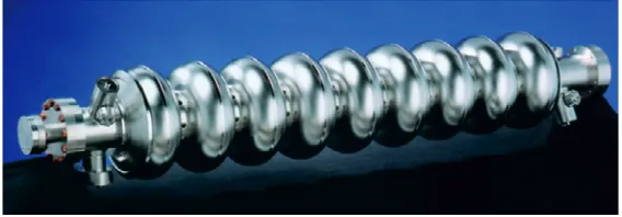
4.1 High gradient superconducting RF cavities
In 2004, after a careful comparison of the available technology options, the International Technology Recommendation Panel [4] recommended superconductive RF cavities as the most promising tech-nique to be used for particle acceleration in a 500 GeV centre-of-mass energy collider. These cavities will run at an accelerating gradient of 31.5 MV/m at a frequency of 1.3 GHz, in a 2 K bath of superfluid helium. Each cavity consists of 9 cells, for a total of 1.038 m of effective accelerating length.
The important properties of an acceleration technology are the achievable gradient, which deter-mines the overall length of the accelerator, the efficiency with which electrical power can be trans-ferred to the beam, and the cost of the whole system. The most obvious, and important, advantage of SCRF technology is the high efficiency which which power is transferred to the beam, even when the substantial power requirements for liquid helium refrigeration are taken into account. This efficiency not only reduces the electricity bill itself, it also limits the necessary investments into electrical power stations, RF equipment, and cooling infrastructure.
The four large cost drivers that have to be balanced in the main linac design are the number of accelerating cavities, the tunnel length, the amount of RF power (both peak and average power), and the cryogenic refrigeration capacity. For a given target beam energy, a higher accelerating gradientg reduces the number of cavities and the necessary tunnel length, but leads to increased demands of RF and refrigeration power, because the energy content and the dynamic losses within a cavity grow as g2. The second important parameter of a cavity is the quality factorQ
0, which determines the amount of heating incurred by the RF field within the cavity. ILC cavities are designed to achieve at least Q0>1010at their operating gradient.
The technology of the TESLA-type cavities is quite mature, as witnessed by more than 15 years of operation of the FLASH (originally called TESLA Test Facility TTF) accelerator at DESY, which uses cavities and cryomodules of essentially the same design as foreseen for the ILC, and by the current construction of the European X-Ray Free Electron Laser XFEL in Hamburg that will employ 800 TESLA-type cavities. Also the pulsed 8 GeV accelerator of Project X currently planned at Fermilab will be based on this technology.
Table 2.Parameters of the SCRF cavities
Parameter Value
Operating gradientg 31.5 MV/m Gradient in test stand 35.0 MV/m Quality factorQ0 1×10¹⁰
Frequency 1.3 GHz
Cells 9
Material Niobium,RRR≥300
Operating temperature 2 K
Effective length 1.038 m
Shunt impedancer/Q 1036Ω
Iris aperture 70 mm
accelerating gradients than the 35 MV/m which are today’s state-of-the-art for economically mass-produced cavities rather than the technological limit. This should be kept in mind when higher gradi-ent numbers of novel acceleration technologies that are in more early developmgradi-ent stages are quoted.
Figure 3.A superconducting 9-cell accelerating cavity.
The cavities, which are shown in Fig. 3, are made out of very pure niobium. Research over the last 10 years has focused on the perfection of the industrial production process, with the goal economize the production and at the same time achieve a 90 % yield of cavities that reach the desired gradient (see Tab. 2). The cavities are assembled in 11.8 m long cryomodule comprising either 9 cavities or, for every third module, 8 cavities and a package with a quadrupole, corrector coils, and a beam position monitor. In total, 1855 cryomodules with 16 024 cavities are needed for the ILC.
4.2 Generating electrons and positrons
The positron source is significantly more demanding. The ILC design foresees a positron source based on longitudinally polarized photons that will be generated by a 147 m long helical undulators that will be driven by the 250 GeV electrons from the main linac. The advantages of the helical undulator compared to the more common planar version are an increase of the photon yield by a factor of two, and the longitudinal polarization of the photons, which leads to a polarization of the generated positrons. The E166 experiment at SLAC [18] has proven that this scheme is viable.
4.3 Producing low emittance beams
The beam size is given byσ= √β, whereβis the beta-function defined by the magnetic lattice, and is the emittance of the beam. In particular the small vertical beam size of onlyσy = 5.9 nm that is needed to achieve the desired luminosity demands a very small vertical emittance of the beam, far below emittances that can be produced directly by any electron or positron sources.
This small emittance is achieved with 3.2 km long damping rings operating at 5 GeV beam energy. Within 100 ms, these damping rings reduce the vertical emittance of the electron (positron) beams of 4.6 (80) nm by a factor of 4×10⁴for the positrons down to 2.0 pm, which is comparable to modern third-generation synchrotron light sources. Reaching this small emittance within the allotted time (for the positrons, the time constant is onlyτ = 12.9 ms), however, poses a significant challenge and demands the installation of powerful wiggler magnets to achieve sufficient synchrotron radiation damping. R&D is also necessary for the development of sufficiently fast injection and extraction kickers that allow bunch spacings of 3.2 ns. At KEK in Japan, the Accelerator Test Facility (ATF) has been built to study the technology necessary for low-emittance damping rings and fast kickers.
Another challenge is posed by the beam currents of up to 780 (390) mA for the electron (positron) damping rings, which may cause beam instabilities from fast ions and electron clouds gathering in the beam’s path. At Cornell, the Cesr accelerator has been converted to CesrTA, an accelerator dedicated to the study of electron cloud effects and their mitigation. As a result of these studies, recommenda-tions exist now how to equip the vacuum chambers in the damping ring’s various secrecommenda-tions such that the electron cloud formation is kept under control. The results from CesrTA [19] are invaluable for the construction of future high-intensity storage rings, e.g. for B factories or high-intensity light sources.
4.4 Beam Delivery System
The equationσ= √βtells us that a low emittance is not enough to produce a small beam spot, but that also the beta function needs to be small, only 0.48 mm vertically in the baseline configuration. This demands strong, superconducting final focus magnets as close as possible to the interaction point. Such magnets have been designed for the ILC, similar to designs for final focus magnets at existing accelerators. The absolute beam size, however, of 5.9 nm vertically, is far smaller than at any existing accelerator, and colliding two beams that small is far from trivial. Apart from exceptionally good alignment of all the components and the best possible vibration control, a fast feedback system is the key to success here.
Table 3.Properties of the ILD [20] and SiD [13] detectors.
Parameter ILD SiD Unit
Length (yoke) 13.24 11.35 m
Diameter (yoke) 15.51 12.08 m
Mass 14 700 ∼10 000 tons
Track impact parameter resolution at high momentuma 2 4 μm
Track momentum resolutionδp⊥/p2
⊥ <0.02 0.02 %/GeV
Solenoid field 3.5 5 T
Solenoid warm aperture length×diameter 7.35×6.88 6.07×5.18 m×m Electromagnetic calorimeter energy resolutionδE/√E 17 17 %GeV1/2
Hadronic calorimeter energy resolutionbδE/√E 45 65 %GeV1/2
a: target for both detectors is<5⊕10/p(sin3/2θ).b: resolution for single, neutral hadrons
5 The Detectors
Compared to the harsh conditions encountered at the LHC, the environment at the ILC will be rela-tively benign. As a consequence, detector technologies such as gaseous tracking chambers or CCD pixel detectors can be employed that would be impossible to use at the LHC. Thus, the inherent ad-vantages ofe+e−collisions such as known kinematics and beam polarization are augmented by the possibility to construct and operate detectors with unsurpassed performance.
Two detector concepts are being pursued: The International Large Detector ILD [20], and the Silicon Detector SiD [13]. Some key properties of both detectors are given in Tab. 3. To save costs, the detectors will share one Interaction Region in a push–pull arrangement.
The overall layout of both detectors is rather similar: a pixel vertex detector close to the interaction point is surrounded by a tracking system, dominated by a time projection chamber (TPC) in the case of ILD, while SiD, as the name implies, uses an all-silicon tracker. The main tracker is surrounded by finely segmented electromagnetic and hadronic calorimeters, which in both detectors lie within the solenoid magnet. The magnetic field is contained by a flux return yoke, which must be large enough to constrain the stray field such that work on or calibration data taking with one detector is not impeded by the operation of the detector in beam position.
In both designs, a key issue is to find the right balance between a large and long tracker, a suf-ficiently thick calorimeter, a strong enough magnetic field, and the overall costs. In parallel to the groups of people that work on the overall design, simulation and evaluation of the two detector concepts, independent R&D collaborations have formed that focus on the development of special sub detector systems, for instance the Calice collaboration [21] that works on novel techniques for calorimetry.
In the following, I will briefly pick out two areas where new detector designs are emerging. Both are connected with the desire to optimally measure the properties of quark and gluon jets, namely the jet energy, and the flavor of the primary quark, in particular in the case of charm (c) and beauty (b) quark jets: new calorimeters for energy flow measurements, and new, ultra-thin, ultra-high resolution silicon pixel detectors for lifetime tagging.
5.1 Energy flow calorimeters
electromag-netic calorimeters with excellent resolutions better than 10 %/√Ehave been available since long, the hadronic calorimeters achieve at best 35 %/√E for single hadrons, so that up to the highest hadron energies that can be expected at the ILC, the momentum measurement from the tracker will surpass calorimetric energy information for charged hadrons. Thus it has long been realized that jet energy measurements can be significantly improved if the charged hadron energy information is taken from the tracker, and only neutral hadrons are measured in the hadronic calorimeter, after masking out the showers from charged hadrons. This technique is known as particle flow calorimetry [22], and for it to work one needs a finely grained calorimeter with small Molière radius and an inner radius that is sufficiently large that the particles in a jet are separated spatially so that their showers do not overlap. The Calice collaboration is developing calorimeters that combine lean showers and finely grained, yet affordable readout that fulfill the requirements of particle flow measurements. ILD and SiD would be the first detectors designed specifically for particle flow calorimetry. test beam measurements [23] indicate that the particle flow approach works and will provide the desired resolution.
5.2 Vertex detectors
The identification of a jet’s primary quark’s flavor, in particular in the case of charm and beauty quarks, is of central importance for the physics goals of the ILC. The Higgs boson is expected to decay to beauty quarks with high probability, making beauty tagging a central tool for the selection of Higgs events. Moreover, measuring and comparing the Higgs’ couplings to beauty and charm quarks and to gluons is quite important to answer the question whether the Higgs’ is Standard Model like, or whether a second doublet, as predicted by SUSY models, is needed to explain the observed couplings. Charm and beauty quarks can be well distinguished from light quarks by the presence of hadrons with lifetimes around one picosecond, which manifests itself in tracks that have an impact parameter with respect to the primary vertex. Both, ILD and SiD, have formulated the ambitious goal to measure this impact parameter with a resolution better than 5⊕10/p(sin3/2θ)μm, where p is the particle’s momentum measured in GeV, andθits polar angle. With such a resolution, theb-tagging efficiency and purity, and the ofc/bdiscrimination power, will be far beyond even that achieved at the SLD detector.
This kind of resolution can only be achieved with very thin pixel vertex detectors, with space point resolution around 3μm and a first layer as close to the IP as 15 mm. At this distance, the annual neutron fluence is expected to be around 1011neq/cm2, which is 3 order of magnitudes lower than for the first vertex detector layers at LHC, and thus permits to employ completely different detector designs. Many groups around the world work on designs for a vertex detector suitable for the ILC. Technologies that are being considered are e.g. CMOS sensors, DEPFETs, new CCDs termed FPCCDs, and In-Situ IMage Sensors (ISIS) [24].
6 The Next Steps
The Global Design Effort as well as the ILD and SiD detector collaborations are currently preparing the ILC Technical Design Report (TDR), which will be presented to the public in June 2013, during the Lepton Photon conference in San Francisco, CA.
GeV shall be constructed as a first phase. [. . . ] The machine shall be upgraded in stages up to a center-of-mass energy of∼500 GeV, which is the baseline energy of the overall project. [. . . ] A guideline for contributions to the construction costs is that Japan covers 50 % of the expenses (construction) of the overall project of a 500 GeV machine.”
Provided that the ongoing strategy processes in Europe and the United States also come to the conclusion that the ILC has a strong physics case and should be built in the near future, the ILC could become operational after a 10 year construction and commissioning phase around 2026.
References
[1] M. Tigner, Nuovo Cim.37(1965) 1228.
[2] R. B. Palmer, Ann. Rev. Nucl. Part. Sci.40(1990) 529.
[3] R. D. Heueret al.,Parameters for the Linear Collider,2003, http://www.fnal.gov/directorate/ icfa/LC_parameters.pdf, updated 2006, http://www.fnal.gov/directorate/icfa/ para-Nov20-final.pdf.
[4] Jean-Eudes Augustin et al. [International Technology Recommendation Panel], ITRP Recommendation, unpublished report (2004), http://www.fnal.gov/directorate/icfa/recent_ lc_activities_files/ITRP_Report_Final.pdf.
[5] TESLA: The superconducting electron positron linear collider with an integrated X-ray laser laboratory. Technical design report, Parts 1-6,DESY-2001-011 (2001).
[6] International Linear Collider Reference Design Report. Volume 1: Executive Summary,ICFA Beam Dyn. Newslett.42 (2007) 7 [arXiv:0712.1950 [physics.acc-ph]];Volume 2: Physics at the ILC,arXiv:0709.1893 [hep-ph];Volume 3: Accelerator,arXiv:0712.2361 [physics.acc-ph]; Volume 4: Detectors,arXiv:0712.2356 [physics.ins-det].
[7] E. Elsenet al.,International Linear Collider (ILC): A technical progress report, ANL-11-09 (2011).
[8] ILC Technical Design Documentation, http://www.linearcollider.org/GDE/ technical-design-documentation.
[9] G. Aadet al.[ATLAS Collaboration], Phys. Lett. B716(2012) 1. [10] S. Chatrchyanet al.[CMS Collaboration], Phys. Lett. B716(2012) 30.
[11] J. E. Brauet al.(eds.),International Linear Collider Physics and detectors: 2011 Status Report, CERN-LCD-NOTE-2011-038 (2011).
[12] J. E. Brauet al.,The physics case for an e+e−linear collider,arXiv:1210.0202 [hep-ex] (2012). [13] H. Aiharaet al.[SiD Concept Group],SiD Letter of Intent,arXiv:0911.0006 [physics.ins-det]
(2009).
[14] M. E. Peskin,Comparison of LHC and ILC capabilities for Higgs boson coupling measurements, arXiv:1207.2516 [hep-ph] (2012).
[15] S. Heinemeyer et al.(eds), Implications of LHC results for TeV-scale physics: signals of electroweak symmetry breaking, Submitted to the
Open Symposium of the European Strategy Preparatory Group, 2012,
http://indico.cern.ch/materialDisplay.py?materialId=0&confId=173388.
[16] F. Simon,Top physics at CLIC,Talk at LCWS’12, Arlington, TX, 2012, http://ilcagenda. lin-earcollider.org/materialDisplay.py?contribId=51&sessionId=10&materialId=slides&confId=5468. [17] R. Cavanaughet al.(eds.),Implications of LHC results for TeV-scale physics: new physics with
[18] G. Alexanderet al., Phys. Rev. Lett.100(2008) 210801.
[19] M. A. Palmeret al.(eds),The CESR Test Accelerator Electron Cloud Research Program Phase I Report,2012, https://wiki.lepp.cornell.edu/ilc/bin/view/Public/CesrTA/CesrTAPhaseIReport. [20] T. Abe et al. [ILD Concept Group], The International Large Detector: Letter of Intent,
arXiv:1006.3396 [hep-ex] (2010).
[21] Calice collaboration, home page: https://twiki.cern.ch/twiki/bin/view/CALICE/CaliceCollaboration. [22] M. A. Thomson, Nucl. Instrum. Meth. A611(2009) 25.
[23] C. Adloffet al.[CALICE Collaboration], JINST6(2011) P07005.
[24] C. Damerellet al.,ILC vertex detector R&D report of review committee, ILC-REPORT-2008-016 (2008).
[25] S. Asaiet al.,The Final Report of the Subcommittee on Future Projects of High Energy Physics, 2012, http://www.jahep.org/office/doc/201202_hecsubc_report.pdf.
![Table 1. Parameters of the ILC [8]](https://thumb-us.123doks.com/thumbv2/123dok_us/8203536.1370315/3.482.42.473.98.307/table-parameters-of-the-ilc.webp)
![Table 3. Properties of the ILD [20] and SiD [13] detectors.](https://thumb-us.123doks.com/thumbv2/123dok_us/8203536.1370315/9.482.39.438.101.236/table-properties-ild-sid-detectors.webp)
