Strength evaluation of concrete elements with
non-metallic reinforcement under short-term
dynamic compression
Vasilii Plevkov 1,Igor Baldin1, and Andrei Nevskii1,*
1Tomsk State University of Architecture and Building, Department of Reinforced Concrete and Masonry Structures, 634003, Tomsk, 2 Solyanaya Sq., Russia
Abstract. The article presents a method for calculating the strength of
concrete elements with non-metallic fiber, rod and external reinforcement. The algorithm and the calculation program are shown, which are based on the use of a nonlinear deformation model of the normal section of such elements, taking into account the real deformation properties of materials under static and short-term dynamic loading.
Since the beginning of the 21st century, the civil engineering industry has been replenished
with new types of non-metallic materials for the reinforcement of concrete structures as fiber, bars or textile. The reinforcing filler in the form of high-strength mineral or organic fibers is the basis of these materials. Studies of the properties of such materials and features of the design of concrete structures with new types of non-metallic reinforcement have high relevance and importance for the development of building industry.
Currently, non-metallic materials for the reinforcement of concrete structures can be divided into 3 groups: fiber reinforcement (discrete fibers - DF) to create fiber-reinforced concrete (FRC), composite reinforcement (FRP bars) for core reinforcement and external composite reinforcement (Externally Bonded FRP Systems - EBFS) for strengthening concrete structures.
According to studies [1-4], it is the great differ in the deformation characteristics between of FRC, FRP and EBFS and traditional materials analogues (concrete and core or external reinforcement with steel). Therefore, the existing design models describing the strength of sections of traditional reinforced concrete elements cannot be used to calculate concrete elements reinforced with new types of non-metallic reinforcement. These diagrams require significant refinement, taking into account the real deformation properties at different strain rates.
The behavior of building structures under static and dynamic loads have significant differences [5, 6]. Analysis of the strength of such structures during high-speed deformation, taking into account their survivability, makes it possible to more accurately determine the residual life of building structures, as well as buildings and structures after the effects of excessive dynamic loads [7–9].
The developed method for calculating the strength of normal sections of elements with different combinations of FRC, FRP and EBFS reinforcement under short-term dynamic axial and eccentric compression with small eccentricities is presented in this article. In the following, such elements will be designated as FFE elements.
The developed calculation method is based on the use of a non-linear deformation model of the normal section of reinforced concrete elements. It is based on expressions which characterize the ratio of the calculated efforts from external short-term dynamic loads and the limiting internal efforts values in a normal section.
The calculated efforts values from external short-term dynamic loads in normal sections of FFE elements are determined as a result of numerical or analytical calculation of a building or structure [10-12].
Deformation model can be used to determine the limiting internal efforts in the normal section of compressed FFE element. This model characterizes the strength of the normal section of the FFE element with axial and eccentric compression, taking into account the distribution of deformations of one sign along the height of the section [13].
For this, the normal section of the FFE element with height h is divided into k = 103
layers of the same height (Δ = h/k). Next is the layer-by-layer summation of compressive
efforts in concrete and reinforcement at each stage of changing the deformed state of the normal section model of a compressed FFE element. The compressive efforts values are determined in accordance with the actual deformation diagrams of materials [1, 2, 4, 5, 10, 12] (Figure 1).
a b c
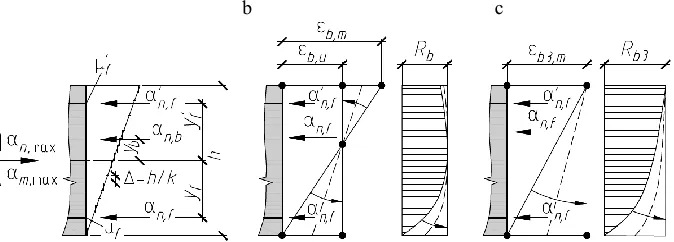
Fig. 1. Design diagram (a) and design models (b, c), which characterize the transition of a normal section from an eccentric compression with an eccentricity of application of a longitudinal force on the boundary of the section core to its axial compression for FFE elements without external reinforcement (b) and external reinforcement (c)
The following notation is taken in Figure 1:
μf , μ’f – the reinforcement coefficients of the normal section of the FRP rods located respectively at the least and most loaded edges of the section, which is equal to the ratio of the cross-sectional areas of the longitudinal reinforcement and elements normal section;
yf , y’f – the distance between the center of gravity of the normal section and the points of application of the resultant efforts in the compressed FRP rods, located respectively at the least and most loaded edges of the section;
yb – the distance between the center of gravity of the normal section and the point of application of the resultant efforts in a compressed FRC;
εb,u – ultimate relative longitudinal deformations of the FRC under short-term dynamic compression;
Rb3, εb3,m and Rb , εb,m – respectively calculated resistances and maximum relative longitudinal deformations of FRC, with and without EBFS under short-term dynamic compression.
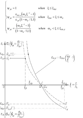
The stresses in the longitudinal FRP are calculated taking into account its deformed state using the relationship (1) between the relative values of stresses ψfd in the longitudinal FRP and the height of the compressed zone ξ of the normal section of the FFE element (Figure 2). This relationship allows us to take into account the resulting stresses in the longitudinal FRP under short-term dynamic loading, including compression. A detailed description of this relationship is given in [14, 15].
1 ,
1
1, 1
1
1 / 1,1
1
1 / 1,1
fd Rd
bd u d
fd Rd d
fd d
d
fd d R d
d
when
when
when
(1)
Fig. 2. Relationship between the value of the relative stresses ψfd in the FRP and the relative height of
the compressed zone of the normal section ξ of FFE-elements: with static (dashed line) and short-term dynamic (solid line) loads
x and h0 – the height of the compressed zone and the working height of the normal
section;
εfc, σfс and εf , σf – longitudinal strain and axial stress in FRP under compression and tension respectively;
εf,u and εfd,u – ultimate longitudinal strain of FRP in tension, respectively, under static and short-term dynamic loads;
Rfc , Rf and Rfc,d , Rfd – calculated values of resistance to compression and tension of FRP, respectively, under static and short-term dynamic loads;
ξR1, ξR and ξR1,d , ξRd – the boundary values of the relative height of the compressed zone of the normal section, at which the stresses in the FRP reach the calculated values of resistance to compression and tension, respectively, under static and short-term dynamic loading;
ω and ωd – the characteristic of the relative height of the compressed zone of the normal
section, at which, respectively, the values of the longitudinal deformations are achieved εf,u
and εfd,u.
The conditions for ensuring the strength of normal sections of dynamically loaded FFE-compressed elements in relative values are:
' , ,max , , ,
nd nd ult n bd n fd n fd
(2)
' , ,max , , ,
md md ult m bd m fd m fd
(3)
Here αnd,max = Nd,max /Rfb,d bh and αmd,max = 8Md,max /Rfb,d bh2 – are the calculated relative values of the longitudinal force Nd,max and bending moments Md,max relative to the center of
gravity of the rectangular concrete section of width b and height h, which are caused by external short-term dynamic loading of a compressed FFE element;
αnd,ult , αmd,ult – ultimate relative internal efforts (longitudinal force and bending moment
relative to the center of gravity of the concrete section), perceived by the normal section of a dynamically loaded compressed FFE element. These efforts are the sum of the relative internal forces perceived by the FRC (αn,cfbd , αm,cfbd) and FRP located at the least (αn, fd , αm, fd) and the most (α’n, fd , α’m, fd) loaded section edges:
,
, ,
, /
' ' 1
x
bd k k
fc d fd f fc d fd f k
nd u
bd bd bd
lt
b
R R
R bh R R
(4)
/
' ' '
, ,
2 ,
, 1 8
8 8
x
b bd k k
fc d fd f f fc d fd f f k
bd bd
bd md ult
y b
R R
R R
R bh
.
(5)
Where:
/
, 1
x
bd k k k
b
the sum of the efforts in compressed FRC on each of the width bk and height Δ = h / k, located along the height of the k layers of compressed zone x of normal section height h;ζf= yf /h and ζ’f= y’f /h – the relative distances between the center of gravity of the normal section and the points of application of the resultant force in the compressed FRP rods, which are located respectively at the least and most loaded cross-section edges.
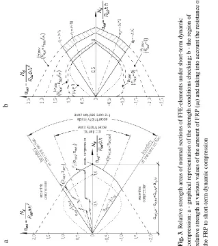
The best visibility is achieved by presenting the results of calculations in graphical form (Figure 3, a). The calculated internal ultimate efforts αnd,ult and αmd,ult in the entire range of form a convex closed surface which characterizes the relative resistance of a normal section to compressive forces under static or short-term dynamic loading.
In Figure 3, the solid line shows the relative strength of the normal section of the FFE element K(αnd,ult , αmd,ult) under short-term dynamic axial and eccentric compression with eccentricities of application of longitudinal force inside the boundary of the section core. The calculated values of the relative efforts from external short-term dynamic compressive loads are presented in the vector form Fi (αnd,i , αmd,i).
Comparison of the calculated combinations of forces from external short-term dynamic loads with the array (area) of the calculated ultimate values of internal efforts is made from the condition:
nd,max, md,max
nd ult, , md ult,
F K , (6)
where F(αnd,max, αmd,max) – is an array of calculated values of relative efforts (longitudinal
forces and bending moments) from external short-term dynamic loads, obtained as a result of analytical or numerical calculation; K(αnd,ult, αmd,ult) – is the boundary of the relative strength of the normal cross-section under short-term dynamic loading.
The difference between the values of the internal ultimate and the calculated external efforts, presented in the coordinate system αnd – αmd of the relative strength areas, which is the margin or overload for the strength of a normal section. If its value takes a positive
value (the vector Fi from the calculated combinations of forces are inside region K), then
the strength conditions (2) and (3) are satisfied and the strength of the normal section is ensured. Otherwise - strength is not provided.
More than 130 numerical calculations of the strength of normal sections of dynamically loaded compressed concrete elements were performed using the developed method. In these
calculations we varied the amount of carbon fiber μcf = 0…0,2 % [1616, 17], carbon FRP
bars μf = 0…3 %, and carbon EBFS μfw = 0…0,12 %, as well as cross-section dimensions
element at different ratios of its height to width: h/b = 1…1,5.
Analysis of the calculations results showed features of the strength values changes of normal sections of FFE elements with axial short-term dynamic compression with small and random eccentricities of the longitudinal force depending on the reinforcement parameters.
Figure 3b shows the change in the boundaries of the relative strength of a normal section of a dynamically loaded compressed FF element (without EBFS) depending on the bar reinforcement coefficient μf at its zero (μf = 0), minimum (μf,min) and maximum (μf,max)
values. The boundaries of the strength of the normal section are expanded in proportion to the increase in μf when taking into account the value of Rfc,d .
An algorithm was developed for calculating the strength of normal sections of dynamically loaded compressed FFE elements, based on the proposed method.
b
Fig . 3 . Re lati v e stre n g th a re as o f n o rm al se cti o n s o f F F E -e lem en ts u n d er sh o rt -term d y n am ic co m p re ss io n : a - g ra p h ica l re p re se n tatio n o f th e stre n g th c o n d it io n s c h ec k in g ; b th e re g io n o f re lativ e stre n g th a t v ario u s v alu es o f th e am o u nt of F RP (μ f ) an d ta k in g i n to a cc o u n t th e re sista n ce o f th e F RP to s h o rt -term d y n am ic co m p re ss io na
The study was done with a support of the state assignment of the Ministry of Education and Science of the Russian Federation (project No.9.6814.2017 / 8.9) and also was funded by RFBR according to the research projects No.18-48-700035 \ 18 and No.18-41-703003 \ 18.
References
1. V. Plevkov, V. Belov, I. Baldin, A. Nevskiy, A.Veselov, E. Serov, Materials Science Forum, 871, 173–181 (2016)
2. V. Plevkov, I. Baldin, K. Kudiakov, A. Nevskii, AIP Conference Proceedings, 1800, 040018-1–040018-5 (2017)
3. A. Nevskii, A. Ustinov, Collection of materials of the international scientific-practical conference "Construction: materials, construction, technology", 156–159 (2018) 4. A. Nevskii, Collection of scientific articles on the results of the second international
round table "Fundamental and applied research in the field of technical and physical and mathematical sciences", 43–46 (2018)
6. N. Popov, B. Rastorguev, A. Zabegaev, Calculation of structures for dynamic and special loads (Vysshaya shkola, Moscow, 1992) (in Russian)
7. G. Odnokopilov, D. Sarkisov, Bulletin of the Tomsk Polytechnic University. Geo Assets Engineering, 328, 85-95 (2017)
8. G. Odnokopilov, D. Sarkisov, E. Butuzov, Bulletin of the Tomsk Polytechnic University. Geo Assets Engineering, 339, 122–135 (2018)
9. G. Odnokopilov, O. Kumpyak, Z. Galyautdinov, D. Galyautdinov, Bulletin of the Tomsk Polytechnic University. Geo Assets Engineering, 330, 110-125 (2019)
10.A. Kolmogorov, V. Plevkov. Calculation of reinforced concrete structures according to Russian and foreign standards (ASV, Moscow, 2014) (In Russian)
11.V. Plevkov, Dynamic strength of concrete and reinforcement of reinforced concrete structures (CNTI, Tomsk, 1996)
12.V. Plevkov, A. Malinovskii, I. Baldin, Vestnik of TSUAB, 2, 144–153 (2013) (in Russian)
13.M. Bodanskii, L. Gorshkov, V. Morozov, B. Rastorguev, Calculation of shelters structures (Stroiizdat, Moscow, 1974) (in Russian)
14.V. Plevkov, I. Baldin, A. Nevskii, Vestnik of TSUAB, 1 (60), 96–113 (2017) (in Russian)
15.V. Plevkov, V. Belov, I. Baldin, A. Nevskii, Vestnik grazhdanskikh inzhenerov, 2 (61), 96–106 (2017) (in Russian)
16.A. Kudiakov, V. Plevkov, V. Belov, A. Nevskii, Voprosy materialovedenia, 1 (85), 66– 72 (2016) (in Russian)
17.A. Nevsky, K. Kudyakov, I. Danke, A. Kudyakov, V. Kudyakov, AIP Conference Proceedings, 1698, 070005-1–070005-5 (2016)