Computational Analysis and Improvement of Wind Generator
Stability Using STATCOM and SDBR
Jagdish Hanumant.Pawar M-tech Student Scholar
Department of Electrical & Electronics Engineering, JNTU Hyderabad
SRINIVAS MODUGU Professor (HOD)
Department of Electrical & Electronics Engineering, Raja Mahendra College of Engineering,
Ibrahimpatanam Telangana, India.
Nikhil Maruti Kunjir M-tech Student Scholar
Department of Electrical & Electronics Engineering, JNTU Hyderabad
Abstract-FACTS devices can be used in wind power systems to improve the transient and dynamic stability of the overall power system. Because of the asynchronous operation nature, system instability of wind farms based on FSIG is largely caused by the reactive power absorption by FSIG (Fixed Speed Induction Generator) due to the large rotor slip during fault. A Static Synchronous Compensator (STATCOM) is applied to a power network which includes a SCIG driven by a wind turbine, for steady state voltage regulation and transient voltage stability support. The STATCOM is controlled by using PQ controller technique with voltage regulation as basic scenario. STATCOM improves the transient voltage stability and therefore helps the wind turbine generator system to remain in service during grid faults. The time to reach steady state torque and speed without using vector control or direct torque control can also be achieved by using this STATCOM control technique. This paper provides an optimized STATCOM control for wind electric generator. The transient behavior of fixed-speed wind farms can be improved by injecting large amounts of reactive power during the fault recovery. This application requires a high dynamic converter, which must also be capable of working under transient unbalanced conditions. The reactive power demand by squirrel cage wind electric generator (SCWEG) during grid faults is not met by capacitor banks installed near SCWEG. This project analyses the transient stability margin of SCWEG which can be increased to a great extend by means of STATCOM. Here the application of Static Compensator (DSTATCOM) for restoring the voltage level at the Wind Farm terminals under fault conditions is considered. Reactive power confirm that the STATCOM provide clear transient stability margin increase The proposed concept can be implemented to Improvement of wind generator using STATCOM and SDBR by using mat lab/Simulink software.
Keywords —Wind Farm, Grid Code, D-STATCOM, Voltage Dips.
I. INTRODUCTION
The most common type of wind turbine consists of squirrel cage induction generator, so it always consumes reactive power, which is not desirable for the distribution system. Also this type of generators slow down the voltage build up after the voltage collapse, this tends to
voltage instability when wind turbine is connected to the distribution system. Due to wind speed variation, wind turbine produce power fluctuations. Therefore it is important to know in advance that how a group of wind turbines integrated with power system distribution network affect the power quality. Power fluctuation in wind turbine is the very important aspect in order to determine the effect of grid connected wind turbine on power quality. As stated in IEC STD 61400-21[6], which provides the measurements and evaluation of the power quality of grid connected wind turbines. This power quality problem can be solve by using custom power devices.
The role of custom power devices [1-2] plays an important role in improving power quality of the distribution system. Custom power devices adopted for the power quality enhancement. Custom power devices such as D-STATCOM, DVR, and UPQC are more commonly employed in distribution system. The concept of custom power is based on the use of power electronics controller in the distribution system for improving power quality of the distribution system.
and equipment, among which are the D-STATCOM (Distribution Static Synchronous Compensator) [2]. The DSTATCOM device is a static compensator designed for distribution systems, which is connected in parallel with the electric grid and can provide/absorb reactive power, thus controlling the bus voltage level and improving the reliability, stability and power quality in medium voltage distribution networks.
II. D-STATCOM (Distribution Static Compensator)
Basic Concept of The D-Statcom a STATCOM employed at distribution side or at load side is called D-STATCOM. The D-STATCOM consists of a VSC, a DC bus capacitor, a coupling transformer connected in shunt with the ac system. STATCOM at transmission level control only the reactive power compensation and provide voltage support. Whereas the D-STATCOM is employed at the distribution level or load side and it also behaves as shunt active filter. A D-STATCOM consists of GTO/IGBT based VSI connected to the power system through coupling transformer. Generally GTOs are used for the high power application like the STATCOM for transmission level. Whereas IGBTs are used for medium to small power application and are used in D-STATCOM [6]. D-STATCOM employs either a voltage source inverter (VSI) or current source inverter (CSI) with reactive power storage as capacitor or inductor respectively. Generally voltage source inverters are widely used because of their lower sizes, less dissipation of heat and less costly capacitor compared to the inductor used in the CSI for the same power rating. So different control techniques can be used for the DSTATCOM such as current controlled D-STATCOM (CCDS) and voltage controlled D-SATCOM (VC-DS). Out of these, CC-VSI is commonly used in the D-STATCOM for the enhancement of the power quality. There is two more subsection under this category as [5], a) Voltage control D-STATCOM: There is a control of active and reactive power flow through the inverter by using DSTATCOM as a voltage source. b) Current control D-STATCOM: This is the most commonly used method for controlling the power through the DSTATCOM by controlling its active and reactive current.
III. PRINCIPLE OF DSTATCOM
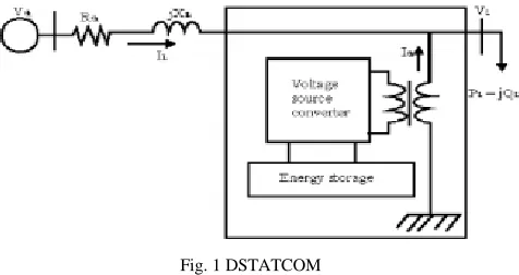
A D-STATCOM (Distribution Static Compensator), which is schematically depicted in Fig.1, consists of a two-level Voltage Source Converter (VSC), a dc energy storage device, a coupling transformer connected in shunt to the distribution network through a coupling transformer. The VSC converts the dc voltage across the storage device into a set of three-phase ac output voltages.
system through the reactance of the coupling transformer. Suitable adjustment of the phase and magnitude of the D-STATCOM output voltages allows effective control of active and reactive power exchanges between the DSTATCOM and the ac system. Such configuration allows the device to absorb or generate controllable active and reactive power. The VSC connected in shunt with the ac system provides a multifunctional topology which can be used for up to three quite distinct purposes: 1. Voltage regulation and compensation of reactive power; 2. Correction of power factor; and 3. Elimination of current harmonics. Here, such device is employed to provide continuous voltage regulation using an indirectly controlled converter.
Fig. 1 DSTATCOM
Fig. 1 the shunt injected current Ish corrects the voltage sag by adjusting the voltage drop across the system impedance Zth. The value of Ish can be controlled by adjusting the output voltage of the converter. The shunt injected current Ish can be written as,
(1) The complex power injection of the D-STATCOM can be expressed as,
(2) It may be mentioned that the effectiveness of the DSTATCOM in correcting voltage sag depends on the value of Zth or fault level of the load bus. When the shunt injected current Ish is kept in quadrature with VL, the desired voltage correction can be achieved without injecting any active power into the system. On the other hand, when the value of Ish is minimized, the same voltage correction can be achieved with minimum apparent power injection into the system.
IV. WIND TURBINE AND ELECTRONIC MODELS
(3)
Where Pt is the extracted power from the wind, ȡ is the
air density [kg/m3], R is the blade radius [m] and Cp is
the power coefficient, which is a function of both tip speed ratio, λ and blade pitch angle, β [deg]. A general
equation used to model Cp ( ), based on the modeling
turbine characteristics is given by
(4) Where the coefficient C1 to C6 are constants:
In this operating mode, the wind turbine pitch control is deactivated and the pitch angle Beta ( ) is fixed at 0°. If the wind speed is above the rated value, the rotor speed can no longer be controlled within the limits by increasing the generator and/or the converter. In this situation, the pitch control is activated to increase the wind turbine pitch angle to reduce the mechanical power extracted
from the wind [4]. The Cp-λ curves are shown in Figure
(2) for different values of Beta.
Fig.2. CP-β curves for different pitch angles.
In order to generate power the induction speed must be slightly above the synchronous speed but the speed variation is typically so small that the WTIG is considered to be affixed speed wind generator [5].
Fig.3. Wind turbine and induction generator.
V. THE STABILITY OF INDUCTION GENERATORS
The normal operating point is obtained when the mechanical torque intersects the electrical torque curve. Assuming generator operating condition, the generator will accelerate during fault in the power system according to the following movement equation:
(5) A typical torque-speed static characteristic of an induction machine is presented in Figure (4).
Fig.4. Typical torque-speed characteristic of an induction machine [6]. During the failure event in the power system the
mechanical torque Tm is practically unchanged; on the
other hand the electrical torque will be reduced since the electrical torque is proportional to the square of terminal voltage. This means that the resulted over speed is a
function of the inertia constant H of the generator, the
duration of the fault and severity of the fault [6] [7]. To improve the transient voltage stability and therefore help the wind during grid faults, an alternative is to utilize dynamic reactive power compensation such as a STATCOM as considered in this study.
VI.MATLAB/SIMULINK RESULTS
Fig.6. shows Voltage on bus 25, Activepower, Reactive power, phase volge Wind turbine rotor speed without STATCOM
Fig.7. shows Active power, Reactive power, Wind turbine rotor speed, wind speed, pitch angle without STATCOM
Fig:8. STATCOM voltage, reactive power without STATCOM
Fig:9. Matlab/Simulink model of proposed 30 MVAR circuit with STATCOM
Fig.10. shows Voltage on bus 25, Activepower, Reactive power, phase voltage, Wind turbine rotor speed for 30MVAR with STATCOM
Fig.11. Active power, Reactive power, Wind turbine rotor speed, wind speed, pitch angle for 30 MVAR with STATCOM
F ig:12. STATCOM voltage, reactive power for 30 MVAR with
Fig:13. Matlab/Simulink model of proposed 3 MVAR circuit with STATCOM
Fig.14. shows Voltage on bus 25, Activepower, Reactive power, Wind turbine rotor speed for 3MVAR with STATCOM
Fig.15. Active power, Reactive power, Wind turbine rotor speed, wind speed, pitch angle for 3MVAR with STATCOM
Fig:16. STATCOM voltage, reactive power for 3MVAR with STATCOM
power, Reactive power, plant voltage and current, motor speed
Fig.19 simulation wave form of Voltage on bus 25
Fig.20. Voltage, current, active power, Reactive power, dc-voltage, wind rotor speed, wind speed, pitch angle
VII.CONCLUSION
Flexible AC Transmission System (FACTS) is one aspect of the power electronics revolution that happened in all areas of electric energy. This paper investigates the using of the STATCOM which is one of the FACTS’s family to support the fixed speed wind power plant in order to
fulfillment the required voltage-dip ride-through
capability. An 85% Low Voltage Ride through LVRT for 150 ms on the grid side is studied based on E.ON grid code. It is applied to 9 MW fixed speed wind farm connected grid. in the wind generation system with SCIG the active power reaches its nominal value faster than in the wind generation systems with DFIG where the active power reaches its nominal value later. The rotor speed of the generator in the DFIG system continues to grow in time although the wind speed is constant.
REFERENCES
[1] Wind Integration: International Experience, WP2: Review of Grid Codes, October 2011
[2] M. Tsili and S. Papathanassiou, “A review of grid code technical requirements for wind farms,” Renewable Power Generation, IET, vol. 3, no. 3, pp. 308–332, Sept. 2009.
COMPARISON OF USING SVC, STATCOM AND DBR’s IMPACT ON WIND FARM INTEGRATION, International Journal of Engineering and Applied Sciences (IJEAS),Vol.2, Issue 4(2010)38-54. [4] CH. AppalaNarayana, D.V.N.Ananth, K.D.Syam Prasad, CH.Saibabu, S.SaiKiran, T. PapiNaidu, “Application of STATCOM for Transient Stability Improvement and Performance Enhancement for a Wind Turbine Based Induction Generator”, International Journal of Soft Computing and Engineering (IJSCE) ISSN: 2231-2307, Volume-2, Issue-6, January 2013.
[5] G. Elsady, Y. A. Mobarak, and A-R Youssef, “STATCOM for Improved Dynamic Performance of Wind Farms in Power Grid”, Proceedings of the 14th International Middle East Power Systems Conference (MEPCON’10), Cairo University, Egypt, December 19-21, 2010, Paper ID 207.
[6] Paulo Fischer de Toledo, Hailian Xie,” TOPIC 7: WIND FARM IN WEAK GRIDS COMPENSATED WITH STATCOM”, KTH, Kungl Tekniska Högskolan, EME department Teknikringen 33-35, Stockholm, Sweden.
[7] M. Jahangir Hossain, Hemanshu R. Pota, Valeri A. Ugrinovskii and Rodrigo A. Ramos,”Simultaneous STATCOM and Pitch Angle Control for Improved LVRT Capability of Fixed-Speed Wind Turbines”, IEEE TRANSACTIONS ON SUSTAINABLE ENERGY, VOL. 1, NO. 3, OCTOBER 2010.
[8] X.P. Zhang, C. Rehtanz, B. Pal, “Flexible AC Transmission Systems: Modeling and Control”, ISBN-13 978-3-540-30606-1, Springer-Verlag Berlin Heidelberg 2006.
[9] O. Noureldeen ,”Characteristics of Fixed Speed Wind Turbines Interconnected Grid during Wind Speed Variations”, 13th Middle East power systems conference MEPCON, 2009 Assuit University, Egypt, December 20-23, 2009.