Design and Analysis of Cylinder and Cylinder
Head of 6-Stroke Si Engine for Weight
Reduction
T. Siva Subramanian1, B. Surendran Murali1, M. Vairamuthu1, M. Vignesh Saravanan, M. Muthu kumar2
U.G. Student, Department of Mechanical Engineering, Francis Xavier Engineering College, Vanarpettai, Tirunelveli, Tamil Nadu, India1
Associate Professor, Department of Mechanical Engineering, Francis Xavier Engineering College,Vanarpettai, Tirunelveli, Tamil Nadu, India2
ABSTRACT: The term six-stroke engine has been applied to a number of alternative internal combustion
engine designs that attempt to improve on traditional two-stroke and four-strokeengines. Claimed advantages may include increased fuel efficiency, reduced mechanical complexity and/or reduced emissions. These engines can be divided into two groups based on the number of pistons that contribute to the six strokes.The present paper deals with design of cylinder & cylinder head with air cooling system for 6 strokes 6 cylinder SI engine. The main objective of design is to reduce weight to power ratio & will result in producing high specific power. The authors have proposed preliminary design cylinder & cylinder head of a horizontally opposed SI engine, which develops 120 BHP and possess the maximum rotational speed of 6000rpm. Four stroke opposed engine is inherently well balanced due to opposite location of moving masses and also it provides efficient air cooling. For the requirement of weight reduction the material selected for design of cylinder and cylinder head is Aluminium alloy 6063 and aluminium alloy 5052.
KEYWORDS: Internal combustion engine, six-storke engine, fuel efficiency .
I.INTRODUCTION
Schematic diagram of the six stroke engine
Comparison of Six Stroke Engine with Four Stroke Engine:
II. LITERATURE REVIEW
This section explains the beneficial aspects in a six stroke engine which does not exist in a four stroke engine .the major difference between four and six stroke engines are the extra two strokes.
G.BahadurVali& Krishna Veni [1] in this project they have design an assemble cylinder and cylinder head. They used two different Aluminum alloys 6061 and 7475.
Abhishek Mote at el [2] they analyze of heat transfer crosswise finned surfaces using CFD software. they thought that experiment based research done by different researchers in the past is a time consuming process.
B. MR. Krishna Kanth .M. and Mr.Srinivas.D: A cycle of six strokes out of which two are useful power strokes due to its thermodynamic cycle and a modified cylinder head with two supplementary chambers: combustion and an air heating chamber, both independent from the cylinder. Several advantages result from this, one very important being increases in thermal efficiency. F. Chinmayeekarmalkar, vivekRaut: The aim of this research is to understand the latest trends in internal combustion engine while maintaining its prime focus on six stroke engine
III. PROBLEM IDENTIFICATION
produced inside the combustion chamber is conducted to all engine parts. Due to this thermal efficiency is reduced. The weight of an engine is also increased.
VI.FINITE ELEMENT METHOD
The principle of the method is to replace an entire continuous domain by a number of sub domains in which the unknown function is represented by simple interpolation functions with unknown coefficients.
1. Discretization or subdivision of the domain
2. Selection of the interpolation functions (to provide an approximation of the unknown solution within an element)
3. Formulation of the system of equations ( also the major step in FEM. The typical Ritz variational and Galerkin methods can be used.)
4. Solution of the system of equations (Once we have solved the system of equations, we can then compute the desired parameters and display the result in form of curves, plots, or colour pictures, which are more meaningful and interpretable.)
BASIC ENGINE DESIGN
Design of Cylinder:
Cylinder Thickness Design:
Thickness of Cylinder is 5 mm.
Cylinder Head Design:
Figure shows the empirical relation for inlet & exhaust valve spacing. Clearance between valve & bore = 2.3 mm
Space between valves (inlet & exhaust) = 9.36 mm Inlet Valve Seat Design:-
Thickness of valve seat (t)i = 3.517 mm Height of valve seat (h)i 9.0558 mm
Exhaust Valve Seat Design:-
Diameter of valve seat (De):- 24.57 mm Thickness of valve seat (t)e = 3.003 mm Height of valve seat (h)e = 7.37 mm
Dimensions of valve seats
Dimensions of cooling fins
VIII.ANALYSIS RESULTS
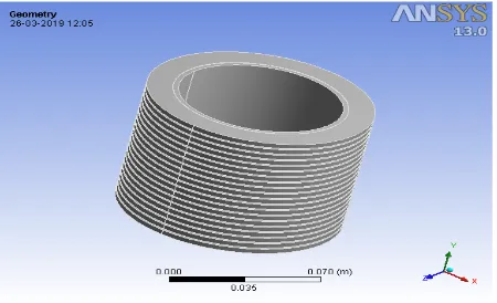
3D MODEL OF CYLINDER
MESHING IMAGE OF CYLINDER
ALUMINIUMALLOY 6063 RESULTS
TEMPERATURE
DIRECTIONAL HEAT FLUX
ALUMINIUM ALLOY 5052 RESULTS
TEMPERATURE
DIRECTIONAL HEAT FLUX
Tabulation of results(Engine cylinder)
COMPARISON CHART TEMPERATURE 3560 3565 3570 3575 3580 3585 S. No Materia l TEMPE RATUR E °C TOTAL HEAT FLUX W/m2 DIRECTIONAL HEAT FLUX W/m2
1 Alumini um alloy 6063
3579.9 5.7409E5 5.4549E5
2 Alumini um alloy 5052
TOTAL HEAT FLUX
DIRECTIONAL HEAT FLUX
ANALYSIS RESULTS FOR ENGINE CYLINDER HEAD 3D MODEL OF CYLINDER HEAD
5.72E+05 5.72E+05 5.73E+05 5.73E+05 5.74E+05 5.74E+05 5.75E+05
MESHING IMAGE OF CYLINDER HEAD
ALUMINIUM ALLOY 6063 RESULTS
TEMPERATURE
DIRECTIONAL HEAT FLUX
ALUMINIUMALLOY 5052RESULTS
TEMPERATURE
DIRECTIONAL HEAT FLUX
Tabulation of results(Engine cylinder head)
COMPARISON CHART: TEMPERATURE: 2900 2950 3000 3050 3100 3150 3200 3250 Aluminium alloy 6063 Aluminium alloy 5052
S.No Material
TEM P °C TOTAL HEAT FLUX W/m2 DIRECTI ONAL HEAT FLUX W/m2
1 Aluminium alloy 6063 3213. 8 4.3628E 6 3.1863E6
TOTAL HEAT FLUX:
DIRECTIONAL HEAT FLUX:
IX. CONCLUSION
The six stroke engine cylinder and cylinder head has been analyzed under thermal analysing for different materials. Aluminium alloy 5052 is compared with the existing material which is Aluminium alloy 6063.In thermal analysis among the two materials, Aluminium alloy 5052 was good compared to other material.In modal analysis, Aluminium alloy 5052 has obtained good results compared to Aluminium alloy 6063 material.
REFERENCES
1. Sae Paper ‘Weight Reduced Engine’(1992): Volume-101 “Journals Of Engine Section3”
2. Chrles Fayette Taylor- “The Internal Combustion Engine In Theory & Practice (Vol.2, Page No.- 425)” 3. A Kolchin& V. Demidov – “Design Of Automotive Engines” (Page No.- 439)
4. V.L.Maleev - “I.C.Engines” (Page No. – 310, 297)
5. Colin R Ferguson - “The Internal Combustion Engine” (Page No. - 313) 6. William H Crouse - “Automotive Engine Design” (Page No. - 218) 7. Julius Mackerle - “Air Cooled Automotive Engines” (Page No. – 204)
8. V.Ganesan - “I.C.Engines”, Second Edition, Pub: Tata Mcgraw Hill (Page No. 4-492) 9. V.Ramanujachari - “Internal Combustion Engine & Combustion” (Page No. – 115,116)
10. Sharma &Purohit - “Design Of Machine Element” (Page No. – 634,635) [11] R.K. Jain - “Machine Design” (Page No.- 1214) [12] B.L. Singhal - ”Applied Thermodynamics” (Page No. – 6-4)
11. Charles Fayette Taylor: “The Internal Combustion Engine in Theory & Practice”, Vol. 12. p. 425. 2. Colin R Ferguson, “The Internal Combustion Engine”, p. 313.
13. Ganesan V, “I C Engines”, Second Edition, Pub: Tata Mcgraw Hill, pp. 4-492. 14. Jain R K, “Machine Design” p. 1214.
15. Julius Mackerle, “Air Cooled Automotive Engines”, p. 204. 16. Kolchin A and Demidov V, “Design of Automotive Engines”, p. 439. 17. Maleev V L, “I.C.Engines”, pp. 310, 297.
18. Ramanujachari V “Internal Combustion Engine & Combustion”, pp. 115, 116. 19. Sharma and Purohit, “Design of Machine Element”, pp. 634, 635)